
Circuit Diagram
Index 1497
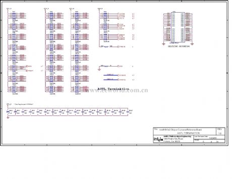
The computer motherboard circuit diagram 810 2 _35
Published:2011/7/20 20:22:00 Author:Ecco | Keyword: computer motherboard
View full Circuit Diagram | Comments | Reading(546)
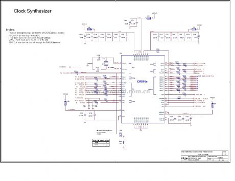
The computer motherboard circuit diagram 810 2_36
Published:2011/7/20 20:26:00 Author:Ecco | Keyword: computer motherboard
View full Circuit Diagram | Comments | Reading(467)
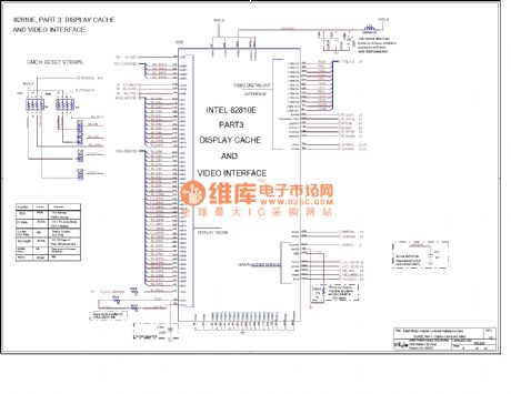
The computer motherboard circuit diagram 810 3_02
Published:2011/7/20 20:28:00 Author:Ecco | Keyword: computer motherboard
View full Circuit Diagram | Comments | Reading(481)
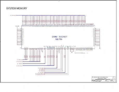
The computer motherboard circuit diagram 810 3_03
Published:2011/7/20 20:28:00 Author:Ecco | Keyword: computer motherboard
View full Circuit Diagram | Comments | Reading(572)
The computer motherboard circuit diagram 810 3_11
Published:2011/7/20 20:31:00 Author:Ecco | Keyword: computer motherboard
View full Circuit Diagram | Comments | Reading(537)
The computer motherboard circuit diagram 810 3_09
Published:2011/7/20 20:30:00 Author:Ecco | Keyword: computer motherboard
View full Circuit Diagram | Comments | Reading(523)
The computer motherboard circuit diagram 810 3_04
Published:2011/7/20 20:33:00 Author:Ecco | Keyword: computer motherboard
View full Circuit Diagram | Comments | Reading(537)
The computer motherboard circuit diagram 810 3_05
Published:2011/7/20 20:34:00 Author:Ecco | Keyword: computer motherboard
View full Circuit Diagram | Comments | Reading(637)
The computer motherboard circuit diagram 810 3_06
Published:2011/7/20 20:45:00 Author:Ecco | Keyword: computer motherboard
View full Circuit Diagram | Comments | Reading(507)
The computer motherboard circuit diagram 810 3_07
Published:2011/7/20 20:49:00 Author:Ecco | Keyword: computer motherboard
View full Circuit Diagram | Comments | Reading(503)
The computer motherboard circuit diagram 810 3_10
Published:2011/7/20 20:31:00 Author:Ecco | Keyword: computer motherboard
View full Circuit Diagram | Comments | Reading(519)
The computer motherboard circuit diagram 810 3_12
Published:2011/7/20 20:32:00 Author:Ecco | Keyword: computer motherboard
View full Circuit Diagram | Comments | Reading(490)
The computer motherboard circuit diagram 810 3_13
Published:2011/7/20 20:32:00 Author:Ecco | Keyword: computer motherboard
View full Circuit Diagram | Comments | Reading(774)
The computer motherboard circuit diagram 810 3_14
Published:2011/7/20 20:25:00 Author:Ecco | Keyword: computer motherboard
View full Circuit Diagram | Comments | Reading(493)
The computer motherboard circuit diagram 810 3_15
Published:2011/7/20 20:26:00 Author:Ecco | Keyword: computer motherboard
View full Circuit Diagram | Comments | Reading(547)
Computer motherboard circuit diagram 810 4_02
Published:2011/7/21 2:58:00 Author:Ecco | Keyword: Computer motherboard
View full Circuit Diagram | Comments | Reading(502)
Winder electronic counter circuit diagram 1
Published:2011/7/21 2:50:00 Author:Ecco | Keyword: Winder electronic counter
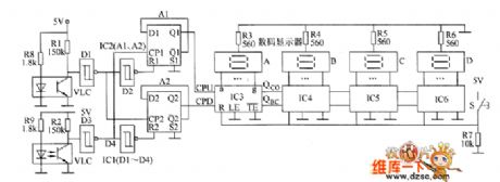
The winder electronic counter circuit is composed of the photoelectric sensor circuit, shaping circuit, plus / minus identification circuit and four-digit counter circuit, and the circuit is shown as the chart. Photoelectric sensor circuit consists of resistors R1, R2, R8, R9 and optocouplers VLC1, VLC2. R1, R8 and VLC1 form the plus counting sensor circuit, and R2, R9 and VLC2 form the subtraction counting sensor circuit. Shaping circuit consists of D1 ~ D4 which are inside of six NOT gate Schmitt trigger integrated circuit IC1.
(View)
View full Circuit Diagram | Comments | Reading(1031)
Winder electronic counter circuit diagram 2
Published:2011/7/21 2:53:00 Author:Ecco | Keyword: Winder electronic counter
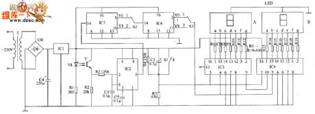
The winder machine electronic counter circuit is composed of the power circuit, infrared switch circuit, plastic / conversion circuit, reset circuit, divider circuit and LED counter circuit, and the circuit is shown as teh chart. Power supply circuit is composed of the power transformer T, bridge rectifier UR, filter capacitor C4 and three-terminal voltage regulator integrated circuit IC1. Infrared switch circuit consists of infrared light-emitting diode VL, infrared phototransistor V and resistors R1 and R2. Reset circuit is composed of the reset button S1, resistors M, R5 and capacitor C3.
(View)
View full Circuit Diagram | Comments | Reading(1575)
Industrial oil burner controller circuit diagram
Published:2011/7/21 2:39:00 Author:Ecco | Keyword: Industrial oil burner, controller
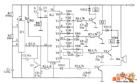
The industrial oil burner controller circuit is composed of the multivibrator, control circuit and fire detection / extinction alarm circuit, and the circuit is shown as the chart. Multivibrator circuit is composed of the time-base integrated circuit IC1, resistors R1, R2 and capacitor C1. Control circuit consists of counting / pulse distributor circuit IC2, reset button S, diodes VD1 ~ VD14, resistors R3 ~ R8, transistors V2 ~ V4, relays K1 ~ K3 and capacitors C3, C5 ~ C7. Fire detection / extinction alarm circuit is composed of the photosensitive resistor RC, transistors V1, V5, resistors R5, R9, capacitors C2, C4, C8 and buzzer HA.
(View)
View full Circuit Diagram | Comments | Reading(3615)
Spark timer circuit diagram
Published:2011/7/21 2:44:00 Author:Ecco | Keyword: Spark timer circuit
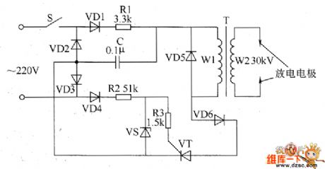
The spark timer circuit is composed of the power switch S, resistors R1 ~ R3, capacitor C, step-up transformer T and the discharge electrode, and the circuit is shown as the chart. When the power switch S is connected and in the positive half cycle of alternating current, the current forms the loop by the VD1, R1, C, VD3, then C starts to charge. In the negative half cycle of AC current, the current forms the loop by VD4, R2, R3, VT and VD2 to make VT be triggered and conduction. R1 selects the 1W metal film resistor, R2 and R3 select 1/4W metal film resistors.
(View)
View full Circuit Diagram | Comments | Reading(1415)
| Pages:1497/2234 At 2014811482148314841485148614871488148914901491149214931494149514961497149814991500Under 20 |
Circuit Categories
power supply circuit
Amplifier Circuit
Basic Circuit
LED and Light Circuit
Sensor Circuit
Signal Processing
Electrical Equipment Circuit
Control Circuit
Remote Control Circuit
A/D-D/A Converter Circuit
Audio Circuit
Measuring and Test Circuit
Communication Circuit
Computer-Related Circuit
555 Circuit
Automotive Circuit
Repairing Circuit