
Circuit Diagram
Index 1484
555 time-base circuit adjustable power charger circuit
Published:2011/7/18 21:33:00 Author:TaoXi | Keyword: 555, time-base, adjustable, power, charger
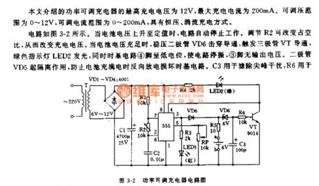
The adjustable power charger circuit which is introduced in this article has the highest charge voltage of 12V, the maximum charging current is 200mA. The adjustable voltage range is 0-12V, the adjustable current range is 0-200mA, and it has the constant voltage, trickle charging mode.
The circuit is as shown in figure 3-2. When the battery voltage rises to the set value, the circuit will stop operating. You can change the charging voltage by adjust the duty ratio of R2. When the voltage of the battery is full, the voltage-regulator diode VD6 punctures the conduction to trigger the conduction of the transistor VT, the green indicator light LED2 turns on, and the pin-4 of time-base circuit has the low level to stop the oscillation of the circuit, the pin-3 has no output voltage.
(View)
View full Circuit Diagram | Comments | Reading(980)
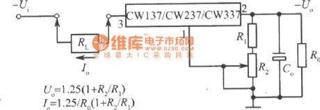
The adjustable constant current circuit formed by CW137/CW237/CW337
Published:2011/7/20 22:13:00 Author:leo | Keyword: Adjustable circuit, constant current
View full Circuit Diagram | Comments | Reading(655)
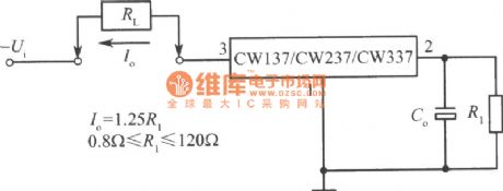
The constant current circuit formed by CW137/CW237/CW337
Published:2011/7/20 22:14:00 Author:leo | Keyword: constant current
View full Circuit Diagram | Comments | Reading(661)
400W inverter circuit
Published:2011/7/18 21:42:00 Author:TaoXi | Keyword: 400W, inverter

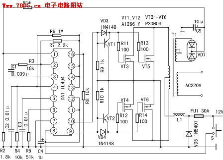
The voltage stabilization sampling and error amplification system is composed of the pin-1 and pin-2, the positive phase input port pin-1 inputs the 15V DC voltage which is rectified and output by the inverter sub-sampling winding, and this 15V DC voltage is divided by R1 and R2 to supply the 4.7~5.6V sampling voltage to the inverter. The reverse phase input port pin-2 inputs the 5V reference voltage which is output by the pin-14. When the output voltage decreases, the voltage of pin-1 decreases too, the error amplifier outputs the low level to rise the output voltage through the PWM circuit. The voltage of pin-1 is 5.4V, the voltage of pin-2 is 5.0V, the voltage of pin-3 is 0.06V. At this time the output AC voltage is 235V (square wave voltage).
(View)
View full Circuit Diagram | Comments | Reading(2926)
3.0A-1.5A adjustable current charger circuit
Published:2011/7/18 22:20:00 Author:TaoXi | Keyword: adjustable, current, charger
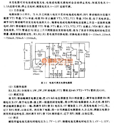
The circuit is as shown in figure 3-3. When the battery or storage battery which has lacking voltage is connected between A and B, the partial voltage value of the RP1's sliding port can not conduct VT5, the VT4 conducts, the resistance R9 is in the positive bias condition to conduct VT3, VT2, VT1, the VT6 turns on, the circuit is in the charging state. You can change the charging current by adjusting RP2's sliding port. As the voltage of the battery or the storage battery is gradually increased, the partial voltage value of the RP1's sliding port conducts VT5, the VT4, VT3, VT2, VT1 conduct, the VD6 turns off to indicate the end of charging. VT1 sets three emitter resistances with different resistance values through S2.
(View)
View full Circuit Diagram | Comments | Reading(692)
12V/5A storage battery automatic charging device
Published:2011/7/18 22:30:00 Author:TaoXi | Keyword: 12V/5A, storage battery, automatic, charging device
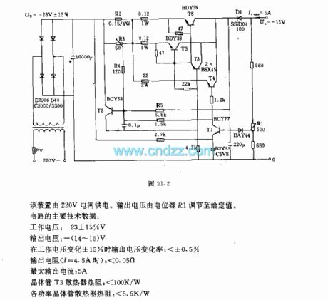
This device uses the 220V power grid as hte power supply. The output voltage is adjusted to the set value by potentiometer R1.
The main technical data:
Operating voltage:-23+/-15%V;Output voltage:-(14-15)V;Output voltage changing rate (when the operating voltage changing rate is +/-15%):<+/-0.5%;Output resistance (I=4.5A):<0.05Ω;Maximum output current:5A;Transistor T3 radiator thermal resistance:<100K/W;Each power transistor radiator thermal resistance:<5.5K/W.
(View)
View full Circuit Diagram | Comments | Reading(1133)
YN5201 (electric fan) infrared remote control decoder circuit
Published:2011/7/21 3:36:00 Author:TaoXi | Keyword: electric fan, infrared, remote control, decoder circuit
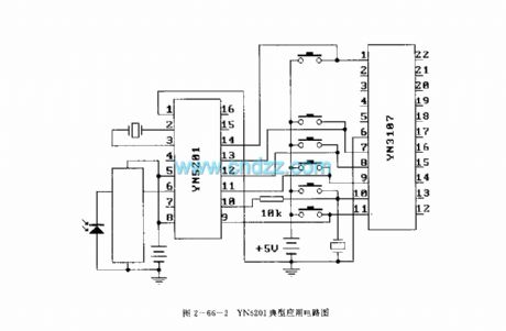
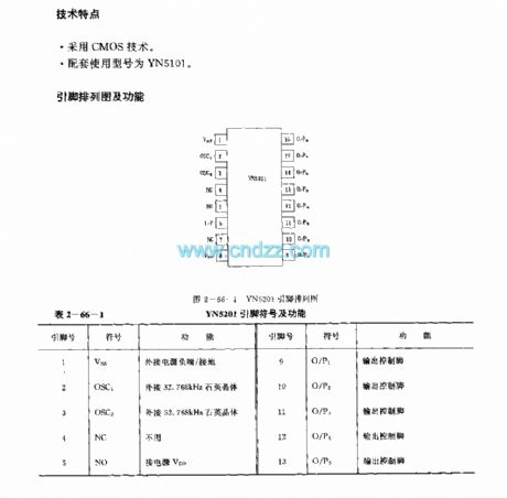
Features
It uses the CMOS technology;The matching model is YN5101.
(View)
View full Circuit Diagram | Comments | Reading(1141)
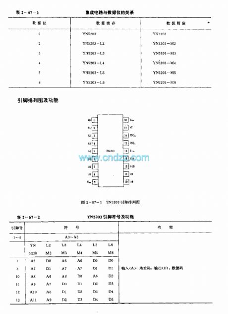
YH5203 (anti-theft system) radio or infrared remote control decoder circuit
Published:2011/7/21 3:46:00 Author:TaoXi | Keyword: anti-theft system, radio, infrared, remote control, decoder circuit
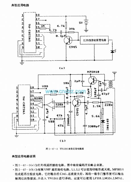
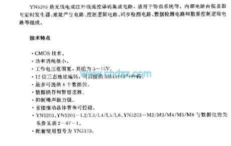
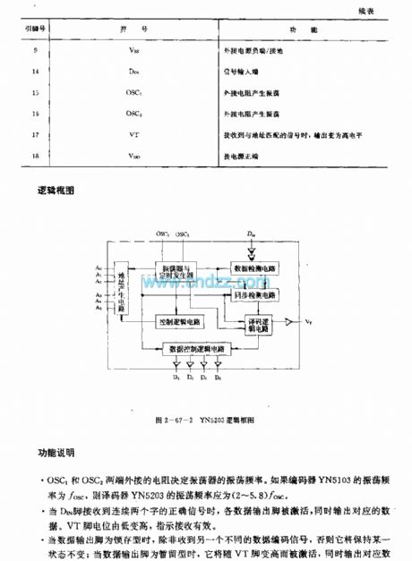
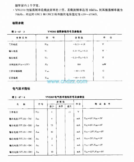
The YH5203 is designed as one kind of radio or infrared remote control decoder circuit that can be used in the anti-theft system. The internal circuit is composed of the oscillator, the timing generator circuit, the address generator, the control logic circuit, the synchronous detection circuit, the data detection circuit and the data control logic circuit.
Features
The CMOS technology.The power consumption is low.The operating voltage range is wide, the value is 3-15V.The 12-bit three states address coding can supply 531441 kinds of code.The six data position.The data latching and persistence selection.The strong ability to reduce the noise. It can promote the transistor and SCR directly.The matching model is YN5103.
(View)
View full Circuit Diagram | Comments | Reading(1522)
YN9101 general remote control receiving circuit (dual-tone multi-frequency signal receiving circuit)
Published:2011/7/21 4:02:00 Author:TaoXi | Keyword: general, remote control, receiving circuit, dual-tone, multi-frequency, signal receiving
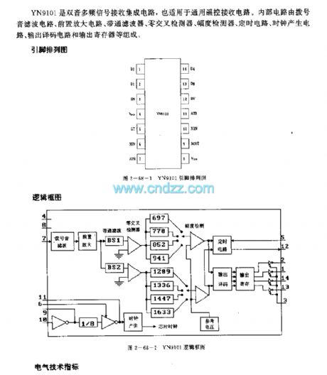
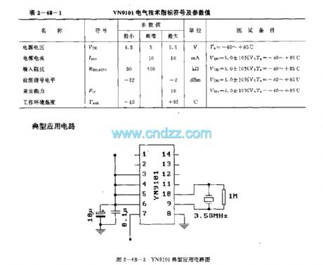
The YN9101 is designed as one kind of dual-tone multi-frequency signal receiving circuit that also can be used in the general remote control receiving circuit. The internal circuit is composed of the dial tone filter circuit, the preamplifier circuit, the bandpass filter, the zero cross detector, the amplitude detector, the timing circuit, the clock generator circuit, the output decoding circuit and the output register.
(View)
View full Circuit Diagram | Comments | Reading(1616)
(TV) infrared remote control receiving circuit
Published:2011/7/21 4:10:00 Author:TaoXi | Keyword: TV, infrared, remote control, receiving circuit
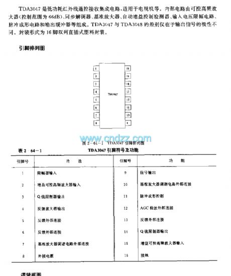
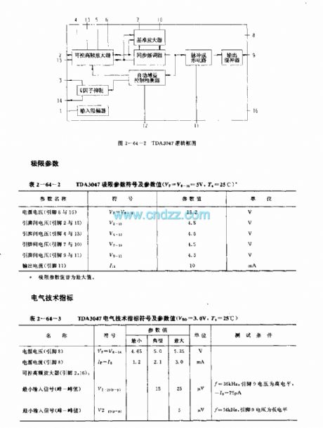
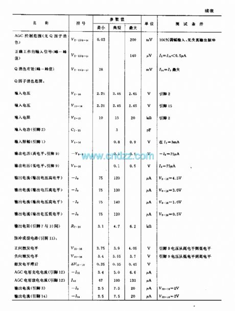
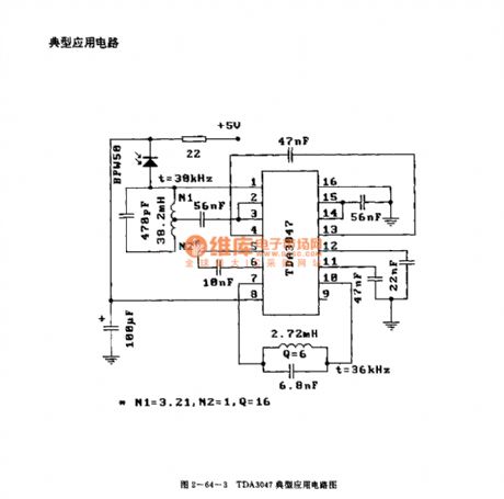
The TDA3047 is designed as one kind of low power consumption infrared remote control receiving circuit that can be used in the TV application. The internal circuit is composed of the controllable high-frequency amplifier (the control range is 66dB), the synchronous demodulator, the reference amplifier, the automatic gain control detector, the input voltage limiter circuit, the pulse shaping circuit and the output buffer. The difference of the TDA3047 and TDA3048 is the polarity of the output signal. This device is in the 16-pin dual-row DIP plastic package.
(View)
View full Circuit Diagram | Comments | Reading(1677)
TDA3048 (TV) infrared remote control receiving circuit
Published:2011/7/21 4:13:00 Author:TaoXi | Keyword: TV, infrared, remote control, receiving circuit
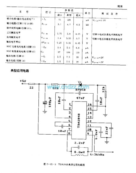

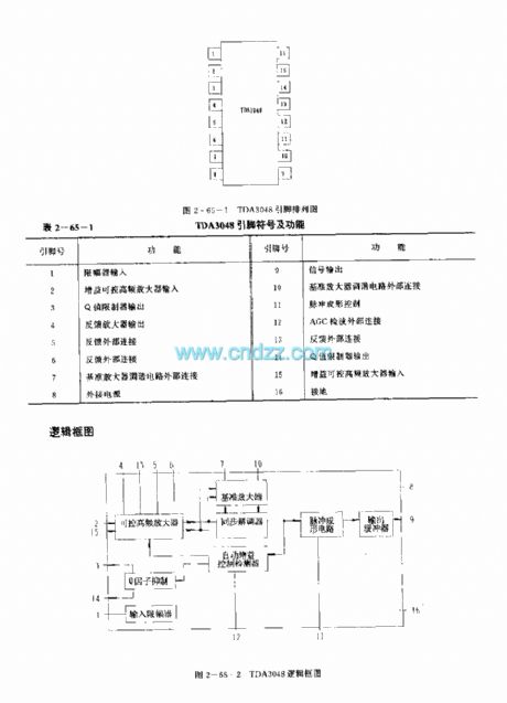
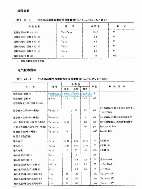
The TDA3048 is designed as one kind of low power consumption infrared remote control receiving circuit that can be used in the TV application. The internal circuit is composed of the controllable high-frequency amplifier (the control range is 66dB), the synchronous demodulator, the reference amplifier, the automatic gain control detector, the input voltage limiter circuit, the pulse shaping circuit and the output buffer. The difference of the TDA3047 and TDA3048 is the polarity of the output signal. This device is in the 16-pin dual-row DIP plastic package.
(View)
View full Circuit Diagram | Comments | Reading(1004)
The function generator circuit formed by 555 timer
Published:2011/7/20 23:21:00 Author:leo | Keyword: Function generator, timer
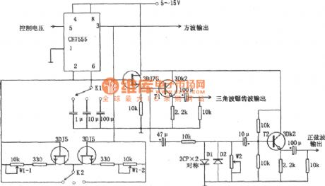
As the picture shows, it is a function generator circuit formed by 555 timer. This circuit is made up of a CH7555 timer, some transistors and RC components, which can generates triangle wave, square wave, sine wave, saw wave and swept wave. All kinds of wave have a adjustable frequency from 0.1 Hz to 100k Hz. The amplitude of vibration of square wave is from 5 V to 15 V which can drive TTL circuit. The accuracy of sine wave is higher than 3%.
(View)
View full Circuit Diagram | Comments | Reading(1929)
TDA2320 (TV) infrared remote control receiving preamplifier circuit
Published:2011/7/21 4:16:00 Author:TaoXi | Keyword: TV, infrared, remote control, receiving, preamplifier circuit
Features
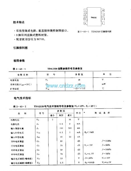
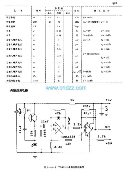
This bipolar type integrated circuit can connected with the micro-controller directly.The 8-pin dual-row DIP plastic package.The matching model is M708.
(View)
View full Circuit Diagram | Comments | Reading(1023)
MAX684 charge-pump drive white light LED circuit
Published:2011/7/13 21:02:00 Author:leo | Keyword: Charge-pump, white light LED
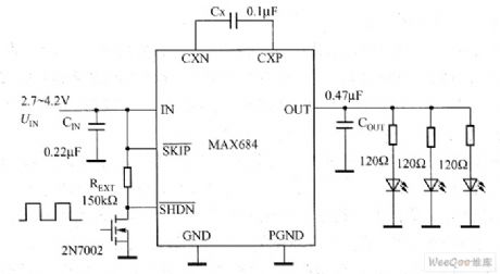
MAX684 charge-pump drive white light LED circuit is like what the picture shows. Its work voltage is from 2.7 V to 4.21 V and can output 5 V voltage and 50mA current. It does not need shielded inductor and just need a resistance and three capacitors. If the practical need is more than three white light LEDs, it can take MAX683 and MAX682 which can offer separately 100mA and 250 mA output current. Especially, the MAX683 can drive more than 16 white light LED which are par ally connected. (View)
View full Circuit Diagram | Comments | Reading(694)
IX0986CE (video tape recorder) infrared remote control receiving preamplifier circuit
Published:2011/7/21 1:29:00 Author:TaoXi | Keyword: video tape recorder, infrared, remote control, receiving, preamplifier circuit
The IX0986CE has the same features, pin arrangement, pin functions, absolute maximum ratings, electrical specifications, logic diagram and the typical applications with the CX20106A, so they can directly exchange. (View)
View full Circuit Diagram | Comments | Reading(432)
IX0310PA (video tape recorder) infrared remote control receiving preamplifier circuit
Published:2011/7/21 1:28:00 Author:TaoXi | Keyword: video tape recorder, infrared, remote control, receiving, preamplifier circuit
The IX0310PA has the same features, pin arrangement, pin functions, absolute maximum ratings, electrical specifications, logic diagram and the typical applications with the uPC1373H, so they can directly exchange. (View)
View full Circuit Diagram | Comments | Reading(457)
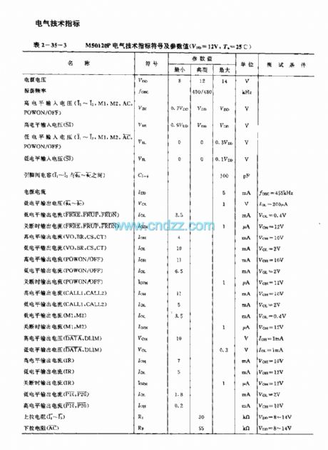
M50120P (TV) infrared remote control launch circuit
Published:2011/7/20 19:38:00 Author:TaoXi | Keyword: TV, infrared, remote control, launch circuit
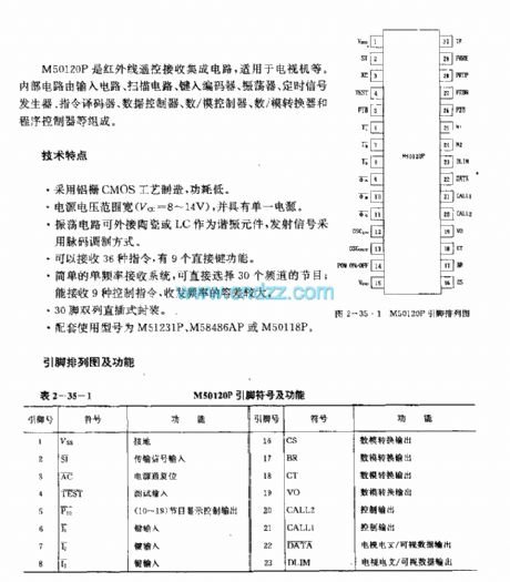
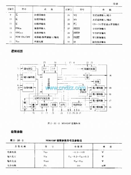
The M50120P is designed as one kind of infrared remote control launch circuit that can be used in TVs. The internal circuit is composed of the input circuit, the scanning circuit, the type coding circuit, the oscillator, the timing signal generator, the instruction decoder, the data controller, the D/A controller, the D/A converter and the program controller.
Features
It uses the aluminum gate CMOS technology;When it uses the single power operating mode, the power voltage is wide (Vcc=8-14V);The oscillation circuit is connected with the ceramic or the LC component to be used as the resonant component, the transmitting signal uses the pulse code modulation mode;It can receive 36 kinds of instructions, and it has nine direct key functions;The simple single frequency receiving system;30-pin dual-row DIP package;The matching models are M51231P, M58486AP or the M50118P.
(View)
View full Circuit Diagram | Comments | Reading(1322)
M50119F (TV) infrared remote control launch circuit
Published:2011/7/20 19:22:00 Author:TaoXi | Keyword: TV, infrared, remote control, launch circuit
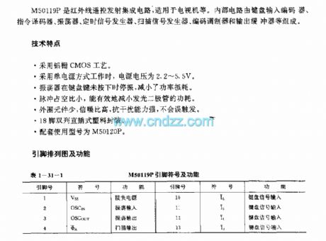

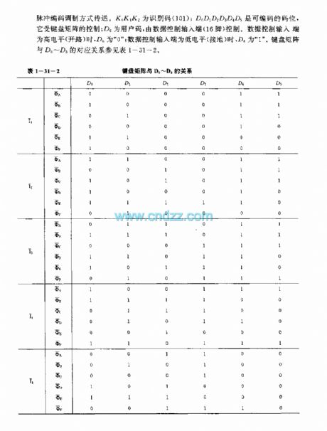
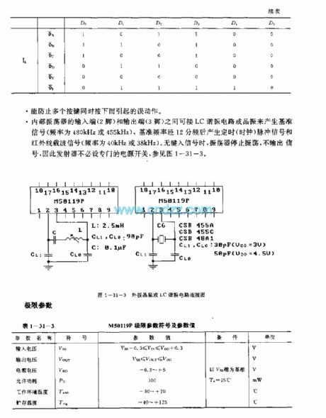
M50119P is designed as one kind of infrared remote control launch circuit that can be used in the TVs. The internal circuit is composed of the keyboard input encoder, the instruction decoder, the oscillator, the timing signal generator, the scanning signal generator, the coding modulator and the output buffer.
Features
It uses the aluminum gate CMOS technology;When it uses the single power operating mode, the power voltage is 2.2-5.5V;When the keyboard button is not pressed, the oscillator will stop oscillating to save the power comsumption;The duty ratio is small to reduce the power comsumption;The little external components, high signal to noise ratio, strong anti-interference ability;18-pin dual-row DIP plastic package;The matching model is M50120P.
(View)
View full Circuit Diagram | Comments | Reading(1432)
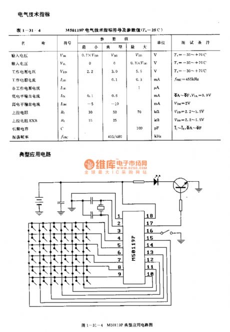
M50125P (TV) 30 functions infrared remote control launch circuit
Published:2011/7/20 19:26:00 Author:TaoXi | Keyword: 30 functions, infrared, remote control, launch circuit, TV
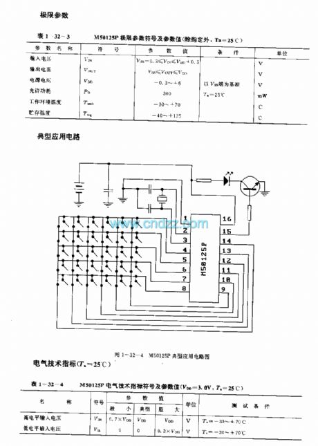
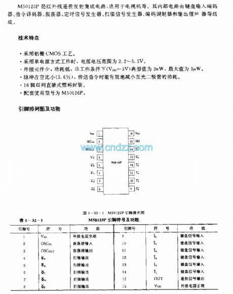
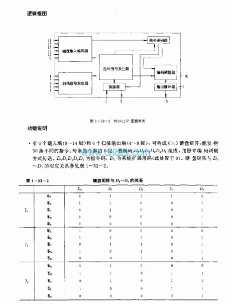
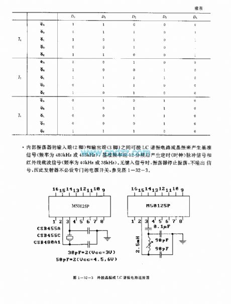
M50125P is designed as one kind of infrared remote control launch circuit that can be used in the TVs. The internal circuit is composed of the keyboard input encoder, the instruction decoder, the oscillator, the timing signal generator, the scanning signal generator, the coding modulator and the output buffer.
Features
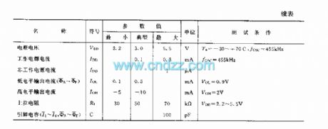
It uses the aluminum gate CMOS technology;When it uses the single power operating mode, the power voltage is 2.2-5.5V;When the keyboard button is not pressed, the oscillator will stop oscillating to save the power comsumption;The duty ratio is small (3.6%) to reduce the power comsumption of the LED;The little external components, high signal to noise ratio, strong anti-interference ability;16-pin dual-row DIP plastic package;The matching model is M50126P.
(View)
View full Circuit Diagram | Comments | Reading(1136)
lX0130CE (TV and audio equipment) 30 functions infrared remote control launch circuit
Published:2011/7/21 1:35:00 Author:TaoXi | Keyword: TV, audio equipment, 30 functions, infrared, remote control, launch circuit
The lX0130CE has the same features, pin arrangement, pin functions, absolute maximum ratings, electrical specifications, logic diagram and the typical applications with the M58484P, so they can directly exchange. (View)
View full Circuit Diagram | Comments | Reading(446)
| Pages:1484/2234 At 2014811482148314841485148614871488148914901491149214931494149514961497149814991500Under 20 |
Circuit Categories
power supply circuit
Amplifier Circuit
Basic Circuit
LED and Light Circuit
Sensor Circuit
Signal Processing
Electrical Equipment Circuit
Control Circuit
Remote Control Circuit
A/D-D/A Converter Circuit
Audio Circuit
Measuring and Test Circuit
Communication Circuit
Computer-Related Circuit
555 Circuit
Automotive Circuit
Repairing Circuit