
Circuit Diagram
Index 1486
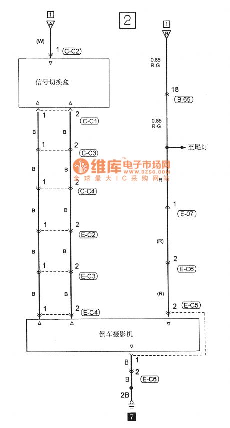
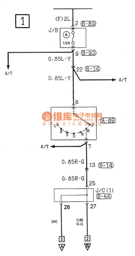
Southeast Ling Sheng car backing camera electric system circuit
Published:2011/7/20 21:21:00 Author:leo | Keyword: Car backing camera, electric system
View full Circuit Diagram | Comments | Reading(792)
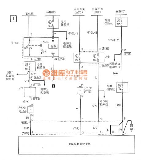
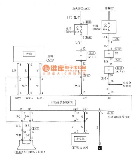
Southeast Ling Sheng mobile radio electric system circuit
Published:2011/7/20 21:24:00 Author:leo | Keyword: Mobile radio, electric system
View full Circuit Diagram | Comments | Reading(724)
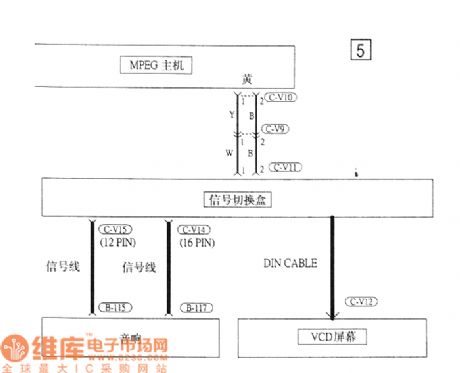
Southeast Ling Sheng audio(VCD) electric system circuit
Published:2011/7/20 21:26:00 Author:leo | Keyword: Audio(VCD), electric system
View full Circuit Diagram | Comments | Reading(725)
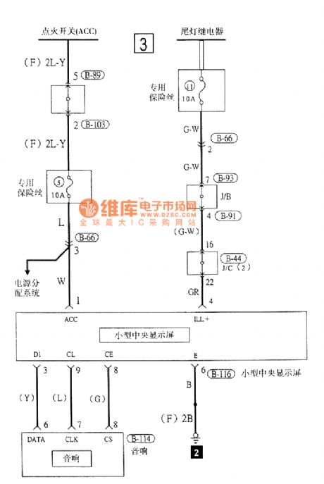
Southeast Ling Sheng audio(small central screen) electric system circuit
Published:2011/7/20 21:30:00 Author:leo | Keyword: Audio(small central screen), electric system
View full Circuit Diagram | Comments | Reading(567)
wireless remote control dimmable lamp(1)
Published:2011/7/19 23:43:00 Author:chopper | Keyword: wireless, remote control, dimmable lamp
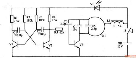
Decorative lights like general droplights are not of remote control and dimming functions,and they are very uneasy to use. This example describes the wireless remote control dimmable droplight, which is with power on/off and multi-level dimming functions,and the control distance is about 20m. The principle of circuitThe wireless remote control dimmable droplight circuit is formed by the wireless remote control transmitter circuit and wireless receiver dimmable controller circuit. Wireless remote control transmitter circuit is formed by the astable multivibrator,high-frequency oscillator,which is shown in Figure 1-197
(View)
View full Circuit Diagram | Comments | Reading(1315)
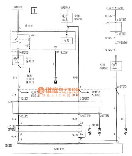
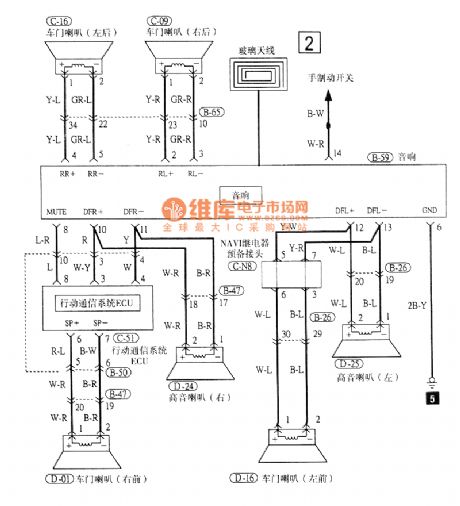
Southeast Ling Sheng audio electric system circuit
Published:2011/7/20 21:28:00 Author:leo | Keyword: Audio, electric system
View full Circuit Diagram | Comments | Reading(644)
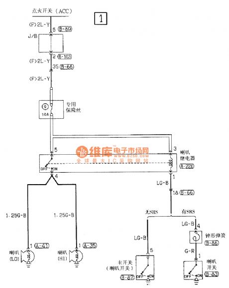
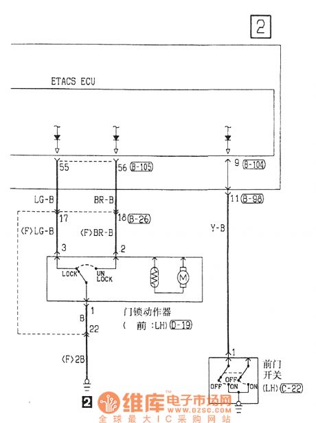
Southeast Ling Sheng speaker electric system circuit
Published:2011/7/20 21:32:00 Author:leo | Keyword: Speaker, electric system
View full Circuit Diagram | Comments | Reading(605)
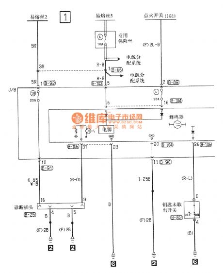
Southeast Ling Sheng key checking buzzer electric system circuit
Published:2011/7/20 21:34:00 Author:leo | Keyword: Key checking buzzer, electric system
View full Circuit Diagram | Comments | Reading(778)
seeder spray pipe water break alarm (2)
Published:2011/7/19 23:25:00 Author:chopper | Keyword: seeder, spray pipe, water break alarm
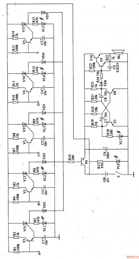
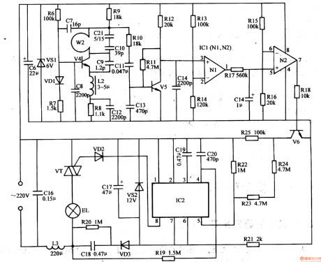
The principle of circuitThe seeder spray pipe water break alarm circuit is formed by water break detection circuit and the sound and light alarm circuit,which is shown in Figure 4-103. The water break detection circuit is formed by the transistors V1-V5,resistors R1,R2,R4,R5,R7,R8,R10,R11,R13,R14 and capacitors C1-C5. The sound and light alarm circuit is formed by the transistors V6-V10,thyristors VT1-VT5,LEDs VL1-VL5,resistors R3,R6,R9,R12,R16,R18-R25,capacitors C7-C9 and speaker BL. The VT1-VT5 and VL1-VL5 and R3,R6,R9,R12 form the LED indication circuit; and VD1-VD5,R16,V6 and C6 form the control circuit.V7,V8,and R18-R22, C7,C8,VL6,VL7 form multivibrator circuit; V9,V10 and C9,R23-R25 form the controlled audio oscillator circuit. The sides A-E are connected to 5 water pipes respectively. R17 is a current limiting resistor, VL6 is the power indicator.
(View)
View full Circuit Diagram | Comments | Reading(531)
seeder spray pipe water break alarm (4)
Published:2011/7/19 23:43:00 Author:chopper | Keyword: seeder, spray pipe, water break alarm
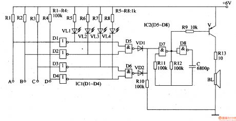
The principle of circuit The seeder spray pipe water break alarm circuit is formed by the water break detection circuit,LED indication circuit,trigger control circuit and the alarm circuit,which is shown in figure 4-105. The water break detection circuit consists of non-gate integrated circuit IC1(D1-D4)and resistors R1-R4. The ends A-D are respectively connected with four water pipes.LED indication circuit consists of resistors R5-R8 and LED VL1-VL4. Trigger control circuit consists of the non-gate D5,D6 in the non-gate integrated circuit IC2 (D5-D8) and diodes VD1,VD2,resistor R10. (View)
View full Circuit Diagram | Comments | Reading(588)
The constant current power resources circuit formed by CW117/CW217/CW317 (Output current is adjusted from zero)
Published:2011/7/20 22:26:00 Author:leo | Keyword: Constant current, power resources
View full Circuit Diagram | Comments | Reading(697)
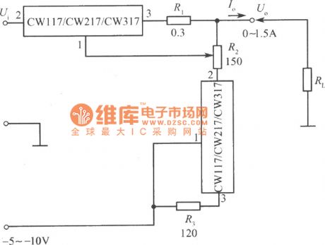
Standard constant current power resources formed by CW117/CW217/CW317
Published:2011/7/20 22:33:00 Author:leo | Keyword: Constant current, power resource
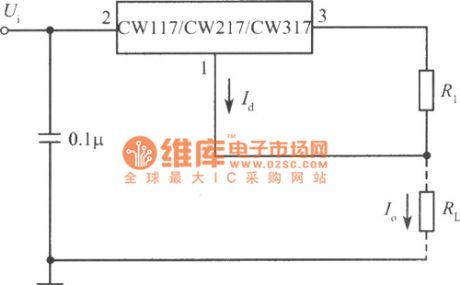
This integrated AVR has three adjustable ports with the lowest base voltage of 1.25 V which have perfect performance on keeping a steady output voltage. Besides, adjustable port has a super small current which is only about 50μA and super steady with a difference of 0.5 μA. Therefore, it can be used to form constant current and high frequency circuit. Its output current is Id plus 1.25/R1. Id is small so Io can be regarded as about 1.25/R1. (View)
View full Circuit Diagram | Comments | Reading(662)
straw feed grinder control circuit
Published:2011/7/19 23:18:00 Author:chopper | Keyword: feed grinder, control circuit
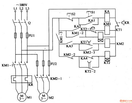
This example describes the straw feed grinder control circuit,which can automatically control the working status of two electric motors. The principle of circuit The straw feed grinder control circuit is formed by knife switch Q,fuses FU1,FU2,thermal relay,AC contactors KM1,KM2,time relays KT1,KT2, intermediate relay KA and control buttons S1,S2,which is shown in Figure 4-129. The main loop of cropping motor M1 is formed thermal components like the normal open main contact KM1-1,KR of Q,FU1,KM1. The main loop of feed motor M2 is formed by normal open main contact KM2-1 of KM2 and Q,FU1,FU2.
(View)
View full Circuit Diagram | Comments | Reading(2167)
500 MA USB compatible Nimh battery charge control circuit--CN3058
Published:2011/7/12 5:12:00 Author:chopper | Keyword: 500 MA, USB compatible, Nimh battery, charge control, Section 1-4, high efficiency
Overview :CN3058 is a charger circuit which can charge rechargeable batteries like single lithium iron phosphate in constant current/voltage mode.The device includes power transistor,and its application does not require the external current detective resistor and blocking diode.CN3058 only requires few external components,and works under USB bus technology specifications,thus it is ideal for portable applications.Heat modulation circuit can control the chip temperature within safety range if the power consumption of devices is bigger or the environmental temperature is higher. (View)
View full Circuit Diagram | Comments | Reading(1161)
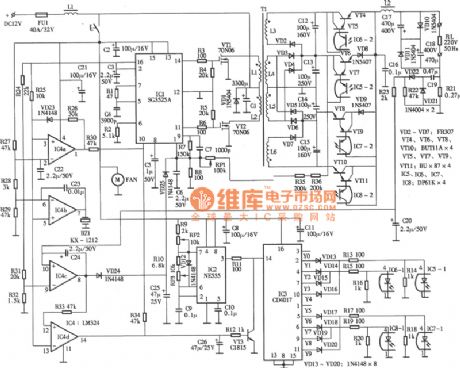
The 100 W to 200 W inverted power supply circuit
Published:2011/7/20 23:56:00 Author:leo | Keyword: 100 W to 200 W, inverted power supply

100 to 200 W inverted power supply circuit
(View)
View full Circuit Diagram | Comments | Reading(689)
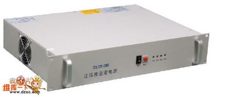
Power special inverting power supply, inverter
Published:2011/7/12 5:14:00 Author:chopper | Keyword: Power, special, inverting power supply, inverter
(View)
View full Circuit Diagram | Comments | Reading(1126)
New type sine wave inverted power supply circuit
Published:2011/7/20 23:52:00 Author:leo | Keyword: Sine wave, inverted power supply
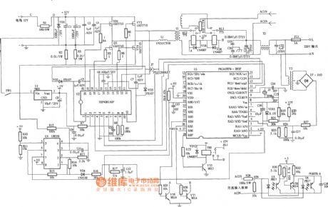
New type sine wave inverted power supply circuit (View)
View full Circuit Diagram | Comments | Reading(1618)
The 300W inverted power supply circuit which is able to connect with inductive load
Published:2011/7/20 23:55:00 Author:leo | Keyword: 300W inverted power supply, connecting with inductive load
The 300W inverted power supply circuit which is able to connect with inductive load
(View)
View full Circuit Diagram | Comments | Reading(1345)
Self-made high power and high efficiency inverted module circuit
Published:2011/7/20 23:51:00 Author:leo | Keyword: High power, high efficiency, inverted module

View full Circuit Diagram | Comments | Reading(1118)
fluid resistance cabinet tanks
Published:2011/7/12 5:14:00 Author:chopper | Keyword: fluid resistance cabinet tanks
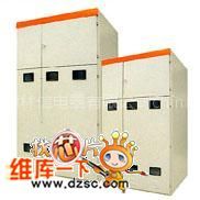
The fluid resistance cabinet tanks our company produced are reliable, affordable.Welcome new and old customers to discuss. (View)
View full Circuit Diagram | Comments | Reading(439)
| Pages:1486/2234 At 2014811482148314841485148614871488148914901491149214931494149514961497149814991500Under 20 |
Circuit Categories
power supply circuit
Amplifier Circuit
Basic Circuit
LED and Light Circuit
Sensor Circuit
Signal Processing
Electrical Equipment Circuit
Control Circuit
Remote Control Circuit
A/D-D/A Converter Circuit
Audio Circuit
Measuring and Test Circuit
Communication Circuit
Computer-Related Circuit
555 Circuit
Automotive Circuit
Repairing Circuit