
Circuit Diagram
Index 1500
Microwave radar automatic lamp circuit(3)(TWH9248/9249)
Published:2011/7/4 22:12:00 Author:zj | Keyword: Microwave radar, automatic lamp
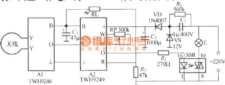
As the diagram shows,it is a automatic lamp which uses TWH9248/TWH9249 microwave emission and receiving sensor made in Guangdong Zhongshan Dahua electronics factory. It has the follow function: When the light at daytime or in room is strong, the lamp will not light up and when it is evening,the lamp will automatically light up.The annular antenna can use Φ3mm enameled wire to bend to Φ150mm circle and to connect to X,Y ports of A1. The circuit needs no debugging, and it can work well. (View)
View full Circuit Diagram | Comments | Reading(911)
Delay singal light battery life circuit
Published:2011/5/13 2:49:00 Author:Nicole | Keyword: singal light, battery life
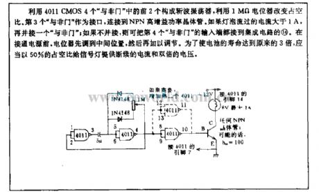
Chopped wave oscillator is composed of the first two 4011 CMOS four NAND gate , the duty ratio is changed by 1MΩ potentiometer. As interface, the third NAND gate is connected to NPN high gain power transistor. If the bulb's current is higher than 1A, then paralleling a NAND gate ; if it does not parallel, you can connect the input terminal of the fourth NAND gate to IC's (14). Before power supply is turned on, potentiometer is adjusted to the middle position, then it can be regulated. In order to make the battery life 3 times longer than before, it should provide singal light discontinuous current and double voltage with 50% duty ratio. (View)
View full Circuit Diagram | Comments | Reading(644)
Xenon flashtube marker circuit
Published:2011/5/13 2:46:00 Author:Nicole | Keyword: xenon flashtube, marker
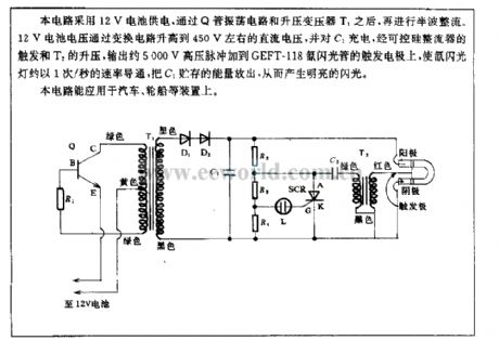
This circuit adopts 12V battery power supply, after Q tube oscillation circuit and step-up transformer T1, then it is half wave rectified. 12V battery voltage will rise to 450V DC voltage by converting circuit, charging to C1, it outputs about 5000V high voltage pulse to add to the trigger electrode of GEET-118 xenon flashtube by the trigger of SCR rectifier and the boost of T2, then the xenon flashtube will turn on with 1/s, discharging the energy stored in C1, to produce bright flashing. (View)
View full Circuit Diagram | Comments | Reading(2460)
Delay light pull switch circuit (2)
Published:2011/7/10 19:58:00 Author:zj | Keyword: Delay light, pull switch circuit
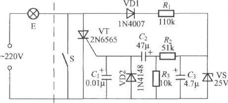
Asthediagramshows it is an improved pull switch delay switch, but the workstability is higher. It has good reliability. (View)
View full Circuit Diagram | Comments | Reading(683)
Automatical noncontact AC regulator circuit
Published:2011/5/13 2:44:00 Author:Nicole | Keyword: AC regulator
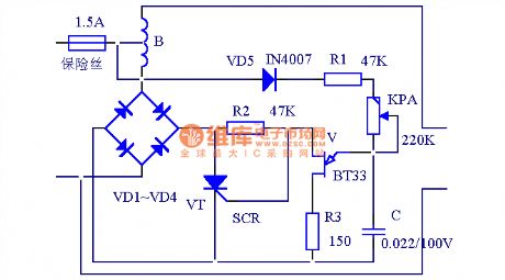
This circuit can adjust output voltage accurately and fast, when mains supply voltage is in the range of 150V~300V.
The circuit is shown as below, after mains supply enters VD1~VD4 full-bridge rectifier by L1, it is added to SCR VT, the conduction angle of VT is controlledbyBT33. A relaxation oscillator is composed of BT33, C, R1, R2, R3, and KP, changing KP can change the oscillation period. When the mains supply voltage rises, the voltage on BT33 rises too, the oscillation becomes quick, the VT conduction angle decreases, the voltage on VT rises, the voltage on L1 dose not change; on the contrary, the voltage on VT drops, the voltage on L1 dose not change; thus the voltage coupled by L2 remains constant. Because it adopts full-bridge rectifier, so the voltage on L1 and L2 are all sine wave.
The current of D1~D4 and VT depends on the capacity of transformer, it should have lager capacity, the compression should be more than 600V, R1 and R2 choose 3W resistance, KPhad batterselectmore than2W adjustable resistance.
(View)
View full Circuit Diagram | Comments | Reading(1916)
Automatical noncontact regulator circuit
Published:2011/5/13 2:44:00 Author:Nicole | Keyword: noncontact regulator
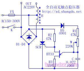
This regulator has no contact, its voltage regulation is precise and fast, the range of application is wide: AC150V~AC300V.
Principle: mains supply enters D1~D4 full-bridge rectifier by L1, it is added to SCR, the conduction angle of SCR is controlled by BT33. A relaxation oscillator is composed of BT33, C, R1, R2, R3, and W, changing W can change the oscillation period. When the input voltage rises, the voltage on BT33 rises too, the oscillation becomes quick, the SCR conduction angle decreases, the voltage on SCR rises, the voltage on L1 is changeless; on the contrary, the voltage on SCR drops, the voltage on L1 dose not change; thus the voltage coupled by L2 remains constant. Because it adopts full-bridge rectifier, so the voltage on L1 and L2 all keep sine wave.
The components selection: the current of D1~D4 and SCR depends on the capacity of B, it should have lager capacity, the compression should be more than 600V, R1 and R2 choose 3W resistance, W had better select more than 2Wadjustable or potentiometer. (View)
View full Circuit Diagram | Comments | Reading(830)
Simple dimmer pull switch circuit
Published:2011/6/30 21:46:00 Author:zj | Keyword: dimmer, pull switch
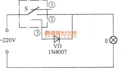
As the diagram shows itis a simple and practical dimmer pull switch. Just pull the switch when use anditlights.Pull theswitch again andlights darken.Pull again and lights extinguish. It is very convenient. (View)
View full Circuit Diagram | Comments | Reading(670)
Full wave optical control circuit
Published:2011/5/13 2:37:00 Author:Nicole | Keyword: full wave, optical control
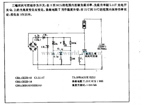
Three terminal TRIAC is used as switch, it controls the load power in the range of 0~90%, the load power changes with the brightness of L14T photoelectric switch Q1. Thermal resistor T is used as temperature compensation, it keeps power constant in the range of 25℃~50℃, the change is within 3%. (View)
View full Circuit Diagram | Comments | Reading(636)
Bridge luminometer circuit
Published:2011/5/13 2:29:00 Author:Nicole | Keyword: luminometer
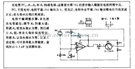
The electric bridge is composed of phototube PC1, R1, R2, R3, differential input terminal of operational amplifier 741 is connected to the middle point of electric bridge both arms.
When PC1 has no light, the electric bridge is balance, 741 output is 0, after it has light, the electric bridge loss balance, 741 output terminal level is directly proportional to the brightness, the meter indicates the brightness value.
The balance adjustment steps of electric bridge: you can shading the phototube at first, adjusting R5 to the maximum value, then adjusting R3 to make the meter indicates 0. To reduce R5, making the meter hand stray away from 0, then adjusting R3 to make the meter indicates 0. To repeat this process, it can obtain the maximum sensitivity. The broken line shows 0.1μF decoupling capacitance. (View)
View full Circuit Diagram | Comments | Reading(922)
Car voltage supervisory circuit
Published:2011/5/12 22:37:00 Author:Nicole | Keyword: car voltage
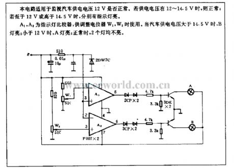
This cirucit is suitable for monitoring whether the 12V car power voltage is normal. If the power voltage is between 12~14.5V, then it is normal; if the voltage is lower than 12V or higher than 14.5V, the indicator light will shine respectively.
A1, A2 are indicator light comparators,they areused to adjust potentiometers W1, W2. When the car power supply is higher than 14.5V, B light turns on; if the power voltage is lower than 12V, A light turns on; if it is normal, the two lights are all off. (View)
View full Circuit Diagram | Comments | Reading(676)
Body induction alarm circuit
Published:2011/5/12 22:31:00 Author:Nicole | Keyword: body induction, alram
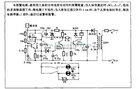
This alarm circuit uses the body distributed capacitance to make a alarm device. When there is nobody closing, BG1, L1, C1 form a multivibrator, relay J is not working; when people are closing the inductor about 1cm, because of the body capacitance, the oscillation circuit will stop vibrating, J starts to work, then the indicator light or warning bellwill alarm. (View)
View full Circuit Diagram | Comments | Reading(1022)
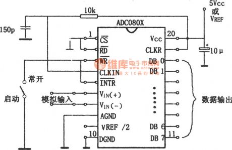
Self-excitation A/D converter circuit composed of ADC0801~0805
Published:2011/7/20 2:39:00 Author:zj | Keyword: Self-excitation, A/D converter circuit
View full Circuit Diagram | Comments | Reading(1715)
PLL FM demodulator(LM565CN\RC4558DN)
Published:2011/7/20 2:50:00 Author:zj | Keyword: PLL, FM demodulator
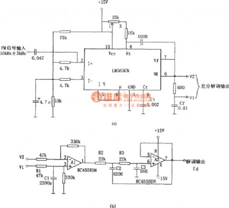
As the diagram shows it adopts LM565CN which consists of 10kHZ±3kHz FM demodulation circuit. The V1 and V2 differential demodulation outputarelevel shiftedand amplificatedby differential amplifier ofA1 in figure b. Thenthe 20kHz pulsating component is filtered by the active LPF composed of A2. (View)
View full Circuit Diagram | Comments | Reading(1547)
Nanosecond pulse test circuit
Published:2011/5/12 22:25:00 Author:Nicole | Keyword: nanosecond pulse, test
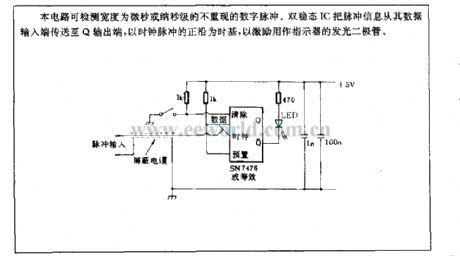
This circuit can test the digital pulse not repeated, and its width is microsecond or nanosecond. Bistable IC transmits pulse information from data input terminal to Q outout terminal, it uses the positive edge of clock pulse as time base, it is used to inspire LED which is used as indicator. (View)
View full Circuit Diagram | Comments | Reading(1051)
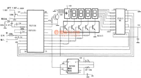
ICL7135(or 5G7135) typical application
Published:2011/7/20 2:50:00 Author:zj | Keyword: typical application
View full Circuit Diagram | Comments | Reading(7415)
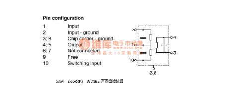
Saw k6265(K) 38MHZ surface acoustic wave filter
Published:2011/7/20 2:51:00 Author:zj | Keyword: 38MHZ surface, acoustic wave filter
View full Circuit Diagram | Comments | Reading(690)
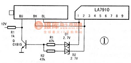
Band conversion circuit composed of LA7910
Published:2011/7/20 2:51:00 Author:zj | Keyword: Band conversion circuit
View full Circuit Diagram | Comments | Reading(3161)
Recorder to microcomputer translation circuit
Published:2011/5/12 4:10:00 Author:Nicole | Keyword: recorder, microcomputer
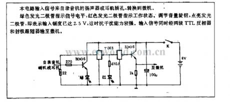
The input singal of this circuit comes from the loudspeaker of recorder or the earphone jack, then it is transformed to microcomputer.
Green LED indicates singal level, red LED indicates work state. Adjusting volume knob and lighting up LED means the input amplitude reaches 2.5V, then the anti-jamming ability is higher. The input singal is transported to microcomputer by two levels TTL inverter and emitter follower. (View)
View full Circuit Diagram | Comments | Reading(580)
Motorcycle ignition circuit
Published:2011/5/12 4:02:00 Author:Nicole | Keyword: motorcycle, ignition
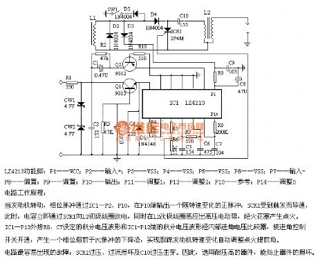
LZ4213 function foot: P1-VCC; P2-input+; P3-VSS; P4-VSS; P5-VSS; P6-VSS; P7-input-; P8-bias; P9-bias; P10-output; P11-adjustment1; P12-adjustment2; P13-reference; P14-adjustment3
The working principle of circuit:When the engine is turning, phase pulsepasses IC1-P2, P10, output a positive pulse in P10 terminal, it changes with rotational speed, SCR1 is triggered and then it is turned on, at this time, capacitance is discharged to L2 primary coilby SCR1 immediately, and inducing high voltage EMF in L2 secondary winding, thenitlights afirethrough spark plug. IC1-P13 external connection of integral voltage waveform set by C7, the integral voltage waveform on IC1-P12 terminal is from internal into angle voltage comparator, the switch is controlled by the angle, it produces a phase which advances the falling edge of PC pulse, it achieves automatic adjustment ignition advance angle by tracking motor rotational speed. (View)
View full Circuit Diagram | Comments | Reading(1398)
Fast simulation switch circuit
Published:2011/5/12 2:24:00 Author:Nicole | Keyword: simulation switch
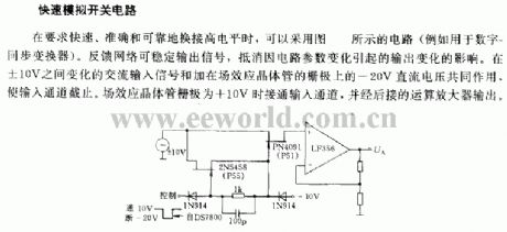
It requires fast, accurate and reliable to change the high level, it can adopt the circuit as shown(such as digital-synchronous converter). The feedback network can steadily output singal, it can counteract the influence of output changes due to the circuit parameter changes. Under the joint actions of AC input singal changes between ±10V and -20V DC voltage on the grid of FET, it makes input channel cut off. when the grid of FET is +10V, the input channel is turned on, then it is exported by the later operational amplifier. (View)
View full Circuit Diagram | Comments | Reading(702)
| Pages:1500/2234 At 2014811482148314841485148614871488148914901491149214931494149514961497149814991500Under 20 |
Circuit Categories
power supply circuit
Amplifier Circuit
Basic Circuit
LED and Light Circuit
Sensor Circuit
Signal Processing
Electrical Equipment Circuit
Control Circuit
Remote Control Circuit
A/D-D/A Converter Circuit
Audio Circuit
Measuring and Test Circuit
Communication Circuit
Computer-Related Circuit
555 Circuit
Automotive Circuit
Repairing Circuit