
Circuit Diagram
Index 1493
Capacitance Driving Circuit with Filter Unit
Published:2011/7/11 22:55:00 Author:Michel | Keyword: Capacitance Driving Circuit
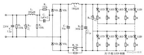
C1, R1, RV1, L1 and R2 constitute the first level power R2 filter circuit, which is used to the input transient momentary high voltage filter.C2, R3 constitutes step-down circuit, C3, C4, L2 and RV2 use rectifying filter circuit.This circuit is double filter circuit and can effectively protect LED from being broken down momentary high voltage.
Picture:Capacitance Driving Circuit with Filter Unit (View)
View full Circuit Diagram | Comments | Reading(576)
DC-DC Conversion Circuit Without Isolation
Published:2011/7/11 22:55:00 Author:Michel | Keyword: DC-DC Conversion Circuit
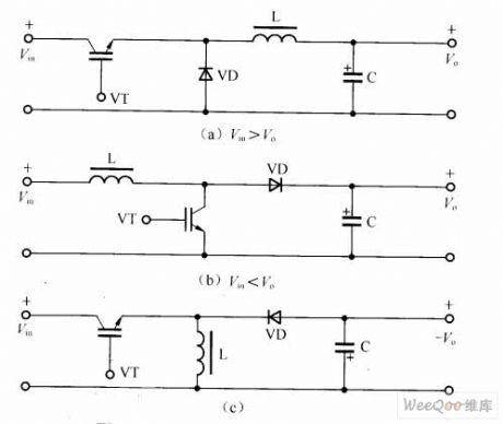
The converter composed of one job switches and L, D, C without input and output voltage isolation and it has three basic forms,namely,buck converter,boost converter and buck-boost converter.And its circuit principle is showed as the aboved pictures.
First,Buck ConverterAs shown in figure (a), 9 is to reduce output ripple, it accesses inductance and capacitance C L on the output side.VD is fly-wheel diode.Output voltage's average value,Vo of buck converter is always lower than Vin. Whether the current iL in inductance is successive depends on switch frequency,filtering inductance L and capacitance C parameter value. (View)
View full Circuit Diagram | Comments | Reading(759)
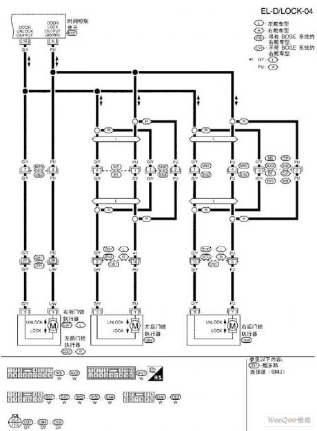
Teana A33-EL power door lock circuit
Published:2011/7/16 2:56:00 Author:leo | Keyword: Power door lock
View full Circuit Diagram | Comments | Reading(593)
Light circuit in case of power failure
Published:2011/7/16 2:57:00 Author:leo | Keyword: Light ciricuit, power failure
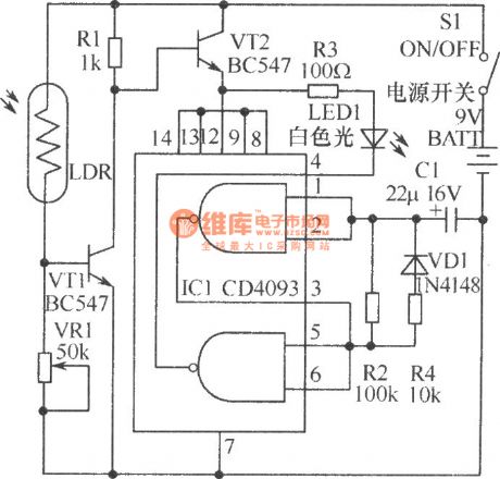
It is not safe for children to walk around in the study when the power is cut suddenly. As the picture shows, it is a light circuit made by LED. This lamp uses battery to supply power and has a low power consumption. If it is set beside the desk, when the power is cut suddenly, it will offer enough light for children’s walking out the room. In order to save the power, LED uses adaptive lighting. IC1 selects CMOS integrated circuit CD4093 and VT1 and VT2 select triode BC547.Other components are shown in the picture. (View)
View full Circuit Diagram | Comments | Reading(991)
Single End Forward DC-DC Converter Circuit
Published:2011/7/11 22:55:00 Author:Michel | Keyword: DC-DC Converter Circuit
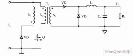
The single end forward DC-DC coverter circuit is showed as above.Among them, the transformer T1 acts as isolation and tranformation and an inductance Lo(flow current inductance) is added to output end,which acts as energy storage and transmission.The transformer primiray level has reset windings Np.In practical applications, the winding uses RCD to absorb can also be replaced.If the chips' auxiliary power supply is provided in the flyback way and part of the adjustable tube peak voltage can also be cutted(It is equivalent to part of the reset winding).Output loop needs a rectifier diode VD1 and a free-wheeling VD2 diode.Transformer uses magnetic cores without the gap thus the copper loses and temperature rising are small and output ripple voltage is small too. (View)
View full Circuit Diagram | Comments | Reading(1120)
ZIVA-4.1 DVD decoding processing integreated circuit diagram
Published:2011/7/16 2:45:00 Author:leo | Keyword: Decoding processing integreated circuit, DVD devices
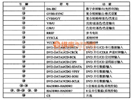
ZIVA-4.1 is a new type of DVD decoding processing integrated circuit. It is widely used in all kinds of DVD devices, for example, BuBuGao series in China and so on.
1.Function Features:The ZIVA-4.1 is used to decode the signals which are from chips and pass through UDE interface circuit. It returns the signals to analog video signals and audio signals. And the analog video signals pass through decoding chip ZIVA-4.1 directly. Audio signals are sent to audio D/A converter and output 5.1 channel analog signals, which are filtered then output.
2.Pin functions and data:ZIVA-4.1 adopts 208 pin package and all functions are shown in the picture. (View)
View full Circuit Diagram | Comments | Reading(742)
MC68HCO5C4-Communication single chip micro computer integrated circuit
Published:2011/7/16 2:45:00 Author:leo | Keyword: single chip micro computer, 24 dual-orientation
MC68HCO5C4 is a kind of single chip micro computer which is widely used in wireless telephone and always be used as thecontrol chip of main engine.1. Inner circuit diagramMC68HCO5C4 adopts CMOS and has 16 bit input snapping and output comparing self-timer system(IC/OC), constant connecting periphery interface SPI, constant connecting communication interface SCI, 24 dual-orientation input and output line, that is AO-PA7, PBO-PB7, PCO-PC7.
2.MC68HCO5C4 can finish 16 bit snapping and output comparing self-timer system. It can also use output comparing function to generate dual-sound multi-frequency DTMF signals, code data signals, impulse dialing signals, gentle tone and so on. (View)
View full Circuit Diagram | Comments | Reading(755)
The amplifer circuit diagram formed by LM118 and used in device
Published:2011/7/16 2:49:00 Author:leo | Keyword: Instrument amplifer
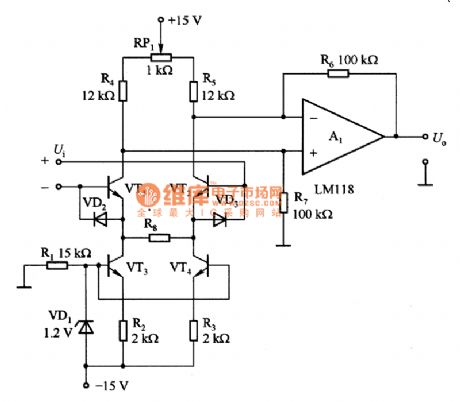
Picture 1 is an instrument amplifier. It is made up of LM118 and others. In this circuit, VT1 and VT2 can form surface input circuit. They can form constant flow source which can supply steady current for differential amplifier A1;VD1 can supply base voltage(1.2V) with zero degree temperature factor to constant flow source. In order to make the input circuit have a good linearity working state, The output current of VT3 and VT4 should be double ofthe current passing through it when being added differential voltage.If needing smaller input current, all resistances should be increased by 100 times and replace LM118 with LM318. (View)
View full Circuit Diagram | Comments | Reading(975)
Common White LED Driving Circuit
Published:2011/7/13 8:25:00 Author:Michel | Keyword: White LED, Driving Circuit
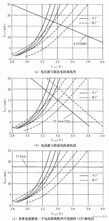
Figure 1 is 4 kinds of common white LED drive circuit and the white LED positive voltage differences will make different impacts to current stable accuracy because different stabilized voltage lines are used. The firgure 2 are six white LED(They are chosen from two manufactuers) positive electric current and forward voltage characteristic curve and , the output voltage stabilizer load curve and lies at the intersection of voltage characteristic curve is the point.
Figure 1: Common White LED Driving Circuit
Circuit shown in figure 1(a) uses voltage source converter and the current limit resistance to control the current white LED and the advantages of the way is that we can choose many kinds of regulators and meanwhile only one end of regulators are connected to white LED. (View)
View full Circuit Diagram | Comments | Reading(762)
A differential value detecting circuit made by LTC1043
Published:2011/7/16 2:50:00 Author:leo | Keyword: Detecting circuit, differential value
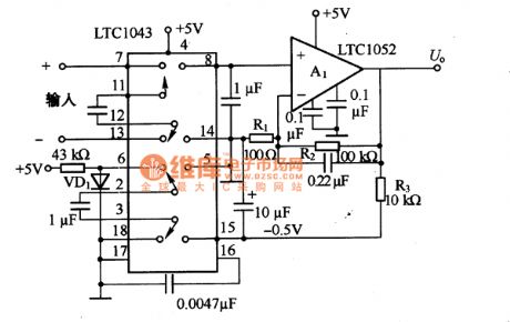
As the picture a and b show, this is a differential value detecting circuit made by LTC1043, in which the differential terminal is changed into single terminal output terminal. Picture20 (a) shows the basic detecting amplifier with speeding up capacitor mode. The sample C1 is connected to differential input signal terminal and uses differential input voltage Ui to charge. And LTC1043 is used to handoff and connect C1 to C2 while the electric charge of C1 is transferred to Q. Due to the repeating frequency of hundreds to some dozens of thousands, voltage of the differential input signals changes to signal input voltage of A1. The repeating frequency is decided by LTC1043 and capacity of C3(EXT capacitor ). (View)
View full Circuit Diagram | Comments | Reading(1161)
A window comparator circuit made by LM311
Published:2011/7/16 2:52:00 Author:leo | Keyword: A window comparator circuit, single polarity voltage
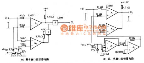
What picture a and b showare a window comparator circuit made by LM311. The picture 14(a) shows a basic comparator circuit input terminal is connected to not-gate window comparator circuit. Input terminal Ui only permits single polarity voltage. When input voltage Ui is lower than the minimum set value UL of window, output high voltage A1 and output low voltageA2 . If the input voltage Ui is higher than UL but lower than UH(maximum), A2 output voltage and the voltage is phase reversalled when passing through inverter. After that, the reversal voltage passes through not-gate phase outputting low voltage which can give a description of the coverage of the window. (View)
View full Circuit Diagram | Comments | Reading(3511)
ULN3814A-The sinle chip audio integrated circuit
Published:2011/7/16 2:53:00 Author:leo | Keyword: Sinle chip, Audio, Integrated circuit
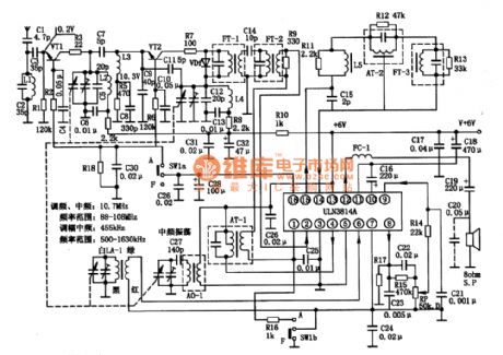
ULN3814A is a kind of integrated circuit used in pocket-sized radio and other kinds of radios.
1.ULN3814A integrated chip inner circuit diagram and pin functions:ULN3814A contains amplitude-modulated oscillator, frequency mixing circuit, frequency-modulating circuit, AGC, AFC, and audio power amplifier as well as voltage-stabilizing circuit.
2.Main parameters of ULN3814A:(1)No-working voltage coverage is from 3 V to 1 V and working voltage coverage is 6 V and 9 V. (2)Output power. Under the condition that Vcc is 7\6 V and R(L) is 8 ohms, the output power is 0.35W. When Vcc is 9 V and R(L) is 8 ohms, the output power is 0.6W.(3)Voltage gain and input resistance. When the voltage gain of the power amplifier is over 40 dB, input resistance is 200kohms. (View)
View full Circuit Diagram | Comments | Reading(908)
LM4766-Hi-Fi stereo amplifier integrated circuit
Published:2011/7/16 2:53:00 Author:leo | Keyword: Stereo amplifier, Integrated circuit
LM4766 is a high-quality stereo amplifier integrated circuit which is a hot Hi-Fi amplifier.
1.LM4766 inner circuit diagram:LM4766 inner circuit has the same function with the amplifier outer circuit. Besides, the inner circuit also contains other protecting circuits. When the voltage is over the maximum value, the circuit will be cutoff automatically. When the load is over the set maximum value or temperature is over 165 oC, the circuit will be closed automatically. The circuit is shown in the picture.
2.LM4766 main parameters:LM4766 has an operating source voltage of 士10 to 土30V. The maximum value of power sources is 土37V. The constant output power average is 40 W with 8 n load.
3.LM4766 classic applying circuit:The classic applying circuit is show in the picture. (View)
View full Circuit Diagram | Comments | Reading(1228)
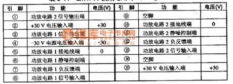
TPA2OOOD2 No filter D type audio power amplifier integrated circuit
Published:2011/7/16 2:55:00 Author:leo | Keyword: No filter, D type, Audio power amplifier, Integrated circuit
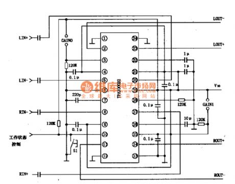
TPA2OOOD2 is a kind of new D type audio power amplifier integrated circuit. It does not need a filter port and beproduced by Texas Instrument Company in America. It is applied to multimedia speaker system of USB drive, portable type DVD player, PDAS and notebook. Besides, it can also be used in audio player with 2 W output power.
TPA2OOOD2 Function Features:The integrated circuit TPA2OOOD2 overcomes the shortcoming of the original D type audio player that needs a big LC filter. It can not only offer high efficiency to D type power amplifier but also reduct the volume of IC components.
(View)
View full Circuit Diagram | Comments | Reading(1339)
CAT3200/CAT3200-5 Charge-pump Driving White LED Circuit
Published:2011/7/13 7:34:00 Author:Michel | Keyword: Charge-pump, Driving, White LED Circuit
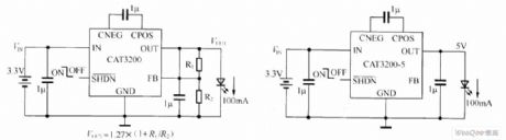
CAT3200 and CAT3200-5 are switch capacitor boost converter and it can output adjustable voltage with low noise.CAT3200-5's output voltage is fixed on 5 V, CAT3200 uses external resistance and the output voltage can be adjusted.Charge-pump with fixed frequency,2MHz is allowed to use small ceramic capacitors and a wider power supply input voltage range (2.7 ~ 4.5 V) can support up to 100 mA maximum output current.Shut-off control input function allows devices to enter closed mode, which makes the source current reduce to less than 1μA.In short-circuit or overload condition, the device gets turn-back current limit protection and overheating protection.In addition, soft start and the conversion rate control surge current when power is on. (View)
View full Circuit Diagram | Comments | Reading(853)
LBl0427A-Communication single chip microcomputer integrated circuit
Published:2011/7/16 2:55:00 Author:leo | Keyword: Communication, single chip, microcomputer, integrated circuit
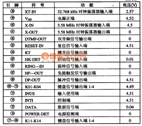
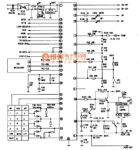
LBl0427A is a kind of communication single chip microcomputer integrated circuit which is widely used in caller ID telephone.
Function features:The integrated circuit LBl0427A contains impulse/duel-frequency signal generator, LCD display drive circuit, FSK/DTMF caller ID decoding circuit, keyboard order coding circuit, hands-free trigger circuit, power resources testing circuit, key sound drive circuit and so on.
Pin functions and data:LBl0427A uses 80 pin package. The pin functions and related data are shown in the picture. (View)
View full Circuit Diagram | Comments | Reading(789)
CXAl279AS analog control integrated circuit
Published:2011/7/16 2:55:00 Author:leo | Keyword: Balance control, stereo system
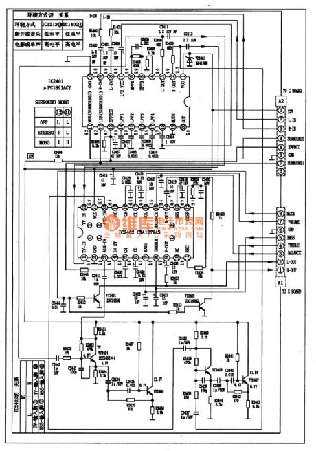
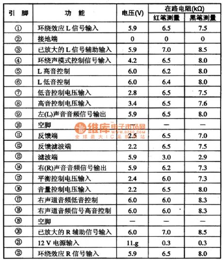
CXAl279AS is a volume, bass, treble, balance control, and mix control integrated circuit produced by Sony Company in Japan, which is widely used in television stereo system and other stereo systems. 1.CXAl279AS classic applying circuitCXAl279AS is usually used with μPCl89lACY to carry out the processing of surround sound signals. Its classic applying circuit is shown in the picture 1.2.CXAl279AS pin functions and data3.Circuit working process(1)Bass/treble/balance control (2)Volume control (View)
View full Circuit Diagram | Comments | Reading(1173)
AAT3110 Charge-pump Driving White LED Circuit
Published:2011/7/13 7:40:00 Author:Michel | Keyword: Charge-pump Driving, White LED Circuit
Capacitance type charge-pump is divided into frequency doubling and fractional frequency according to its boost way.The efficiency of the frequency doubling charge-pump is about 90% and the efficiency of fractional frequency charge-pump is 93%~95%.Capacitive charge-pump is divided into constant voltage output and constant current output according to the output.According to the driving LED way,it is divided into LED parallel constant voltage drive, single constant current driver, series constant current driver etc.Inductive booster device is constant current output, the output voltage is higher and it drives LED in series way.The charge-pump composed of AAT3310 is shown as the picture 1.This charge-pump uses output voltage power supply circuit in parallel manner with the features of few external circuit devices,simple walk line and high conversion efficiency. (View)
View full Circuit Diagram | Comments | Reading(721)
AD521 Solar Lawn Lamp IC
Published:2011/7/13 7:39:00 Author:Michel | Keyword: Solar, Lawn Lamp, IC


AD521 is special IC which is a specially designed for solar LED lighting devices.It consists of switch type circuit, light switch circuit, overdischarging protection circuit, internal integration schottky diodes of circuits, etc.Only an external inductance can constitute solar illumination devices.AD521 uses the patent technology which LED do not glitter when it is off because of undervoltage.
(View)
View full Circuit Diagram | Comments | Reading(687)
ZhongHua saloon car ABS circuit 2
Published:2011/7/11 2:48:00 Author:TaoXi | Keyword: ZhongHua, saloon car, ABS
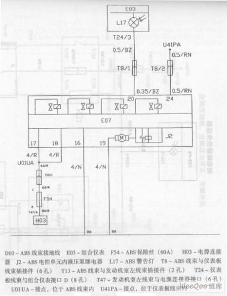
ZhongHua saloon car ABS circuit
D10-ABS wiring harness ground wireE03-Combination instrument F54-ABS fuse (60A)H03-power supply connectorJ2-ABS electric control unit hydraulic pump relay L17-ABS alarm lightT8-ABS wiring harness and dashboard wiring harness plug connector (6 holes)T13-ABS wiring harness and engine room left wiring harness plug connector (2 holes)T24-Dashboard wiring harness and combination instrument interface D (8 holes)T47-Engine room left wiring harness and power supply connector interface (6 holes)U01UA-Connection point, in the ABS wiring harnessU41PA-Connection point, in the dashboard wiring harness (View)
View full Circuit Diagram | Comments | Reading(626)
| Pages:1493/2234 At 2014811482148314841485148614871488148914901491149214931494149514961497149814991500Under 20 |
Circuit Categories
power supply circuit
Amplifier Circuit
Basic Circuit
LED and Light Circuit
Sensor Circuit
Signal Processing
Electrical Equipment Circuit
Control Circuit
Remote Control Circuit
A/D-D/A Converter Circuit
Audio Circuit
Measuring and Test Circuit
Communication Circuit
Computer-Related Circuit
555 Circuit
Automotive Circuit
Repairing Circuit