
Circuit Diagram
Index 1496
The mini wireless call systems BA1401/TDA7010T
Published:2011/7/18 21:47:00 Author:TaoXi | Keyword: mini, wireless call system
Transmitter (View)
View full Circuit Diagram | Comments | Reading(839)
The Remote control automatic door circuit
Published:2011/7/18 21:47:00 Author:TaoXi | Keyword: Remote control, automatic door
Transmitter circuit:
Receiving circuit:
Three-phase positive &negative motor which is controlled by this circuit is as shown:
(View)
View full Circuit Diagram | Comments | Reading(1021)
The Spread Spectrum Rolling code Wireless Tracking Alarm Components KB318/KB318R
Published:2011/7/18 21:46:00 Author:TaoXi | Keyword: Spread Spectrum, Rolling code, Wireless Tracking, Alarm Components
The spread spectrum rolling code wireless tracking alarm component can be used in the situations that need the long distance wireless BP machine type feedback alarm such as the cars, motorcycles and other, it uses the advanced technology and devices, so it has the perfect functions and is better than other similar products. The spread spectrum rolling code wireless tracking alarm component is composed of a wireless transmitter KB318T (or KB923T), and a key buckle type micro receiving alarm KB318R (or KB923R). The remote control transmitter principle figure is as shown:
(View)
View full Circuit Diagram | Comments | Reading(353)
R1212 Driving White LED Application Circuit
Published:2011/7/11 23:48:00 Author:Michel | Keyword: White LED, Application Circuit
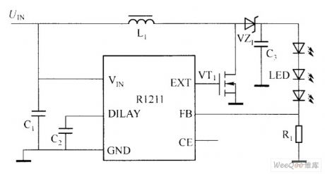
Ricoh R1211 uses CM0S low power consumption and current control switch type boost converter. Its periphery circuit is simple and there is just an inductor, a diode, a mosfet,some resistance and capacitance.The input voltage range is 2.5 ~ 5.5 V and it is suitable for single quarter lithium ion battery or ordinary dry battery power supply. The chip inside uses PWM,which can produce as much as 15 V output voltage and it drives three series white LED.
R1211 series chip adopts the phase compensation feedback loop,which makes whole boost conversion process response more rapidly and output voltage becomes more stable. (View)
View full Circuit Diagram | Comments | Reading(621)
The Digital code control switch digital woven decoder MC145026/MC145027 and the mini radio transceiver module M303S/M303R
Published:2011/7/18 21:46:00 Author:TaoXi | Keyword: Digital code, control switch, digital woven decoder, mini radio transceiver
The digital code control switch digital woven decoder MC145026/MC145027 and the mini radio transceiver module M303S/M303R is as shown. When you press the transmitter button SA, the circuit gets the electricity to start working, the serial coding signal is output from the pin-15 of MC145026 and then it is sent out by the M303S launch module. Receiving module M303R of the receiving circuit receives the serial coding signal, then modulates the encoded signal and sends it to the MC145027 decoder, when the decoder's address and coding are the same, MC145027's decoding effective instruction end outputs the high-level pulse signal, the transistor VT conductsand drives the relay to close, also it completes the switch control function.
(View)
View full Circuit Diagram | Comments | Reading(809)
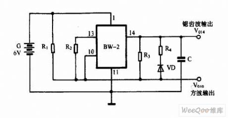
Signal Generator Circuit of BW-2
Published:2011/7/13 7:19:00 Author:Michel | Keyword: Signal Generator, Circuit
View full Circuit Diagram | Comments | Reading(524)
Wireless Security Alarm Circuit of 2051 Design
Published:2011/7/11 7:57:00 Author:Michel | Keyword: Wireless Security, Alarm Circuit
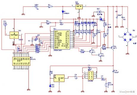
This site to introduce net friend about the core production of wireless security alarm system. The single chip AT89C2051 is used as the central processing chip , which makes the system extension become more convenient.Corresponding soft should be changed if some settings need be altered.This is useful for single chip study.
First,Hardware Design
The circuit principle diagram is shown as above, and it consists of the main wireless access, data decoding, data processing, alarm circuit, output power,alarm display and power supply circuit.The machine receiving frequency is 315M and decoding data uses PT2272 special decoder chip with stable and dependable performance which is widely used in the market.Data processing is completed by the single chip and it is used to distinguish alarm signal,accept all operating instructions and complete the corresponding operation.
(View)
View full Circuit Diagram | Comments | Reading(1822)
Sixteen-channel remote receiver circuit T998C
Published:2011/7/18 21:46:00 Author:TaoXi | Keyword: Sixteen-channel, remote receiver
The key components that will be used in this article:
T998C CD4514 9014
The sixteen-channel remote receiver circuit T998C which is composed of the T998C-12V receiving module and the four-sixteen-channel CD4514 decoder. This circuit can be used as the latch output and the unlatch output, SB is the control switch. When the SB is connected with the VDD, the circuit is in the latch output state, the sixteen output terminalsare not controlled by the Io output state; When the SB is connected with the VDD's output port, the circuit is in the unlatch output state, the output terminalsare controlled by the Io output state. When you are using this sixteen-channel remote receiver circuit, you must follow the two-decimal encoding method, and finish the operation of each channel with the code list. The remote operation code list of the transmitter's each channel is as shown:
(View)
View full Circuit Diagram | Comments | Reading(1424)
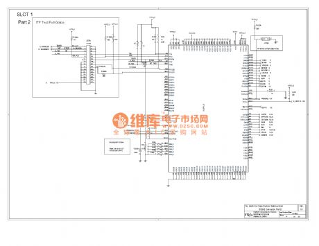
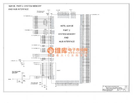
Computer motherboard circuit diagram 810 4_04
Published:2011/7/21 2:56:00 Author:Ecco | Keyword: Computer motherboard
View full Circuit Diagram | Comments | Reading(546)
Computer motherboard circuit diagram 810 4_06
Published:2011/7/21 2:58:00 Author:Ecco | Keyword: Computer motherboard

View full Circuit Diagram | Comments | Reading(528)
Computer motherboard circuit diagram 810 4_07
Published:2011/7/21 2:58:00 Author:Ecco | Keyword: Computer motherboard
View full Circuit Diagram | Comments | Reading(642)
Computer motherboard circuit diagram 810 4_08
Published:2011/7/21 2:59:00 Author:Ecco | Keyword: Computer motherboard
View full Circuit Diagram | Comments | Reading(780)
The computer motherboard circuit diagram 810 4_10
Published:2011/7/20 21:26:00 Author:Ecco | Keyword: computer motherboard
View full Circuit Diagram | Comments | Reading(514)
The computer motherboard circuit diagram 810 4_11
Published:2011/7/20 20:57:00 Author:Ecco | Keyword: computer motherboard
View full Circuit Diagram | Comments | Reading(526)
The computer motherboard circuit diagram 810 4_12
Published:2011/7/20 20:53:00 Author:Ecco | Keyword: computer motherboard
View full Circuit Diagram | Comments | Reading(546)
The computer motherboard circuit diagram 810 4_13
Published:2011/7/20 20:54:00 Author:Ecco | Keyword: computer motherboard
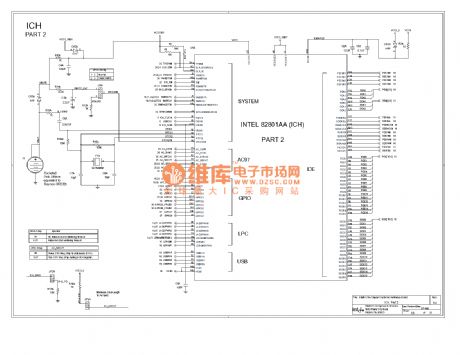
View full Circuit Diagram | Comments | Reading(577)
The computer motherboard circuit diagram 810 4_14
Published:2011/7/20 20:56:00 Author:Ecco | Keyword: computer motherboard
View full Circuit Diagram | Comments | Reading(462)
The computer motherboard circuit diagram 810 4_15
Published:2011/7/20 20:56:00 Author:Ecco | Keyword: computer motherboard
View full Circuit Diagram | Comments | Reading(486)
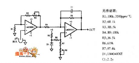
PH meter probe amplification circuit diagram
Published:2011/7/21 2:29:00 Author:Ecco | Keyword: PH meter probe , amplification circuit
View full Circuit Diagram | Comments | Reading(3986)
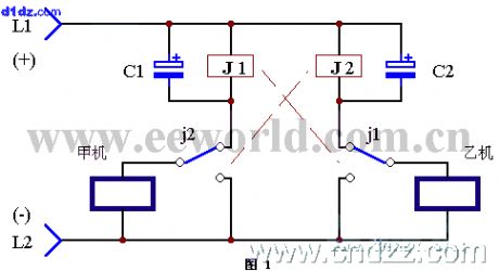
Party line telephone switching equipment 1
Published:2011/7/20 21:32:00 Author:Ecco | Keyword: Party line telephone , switching equipment
View full Circuit Diagram | Comments | Reading(653)
| Pages:1496/2234 At 2014811482148314841485148614871488148914901491149214931494149514961497149814991500Under 20 |
Circuit Categories
power supply circuit
Amplifier Circuit
Basic Circuit
LED and Light Circuit
Sensor Circuit
Signal Processing
Electrical Equipment Circuit
Control Circuit
Remote Control Circuit
A/D-D/A Converter Circuit
Audio Circuit
Measuring and Test Circuit
Communication Circuit
Computer-Related Circuit
555 Circuit
Automotive Circuit
Repairing Circuit