
Circuit Diagram
Index 1491
Regulated Power Supply Circuit with 400V/150mA Output
Published:2011/7/19 11:17:00 Author:Michel | Keyword: 400V/150mA, Regulated Power Supply Circuit
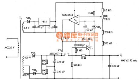
The above picture is regulated power supply Circuit with 400V/150mA output.It is stabilizer of A1 error amplifier of the benchmark voltage (VD4 stable voltage).A1 work power is obtained by voltage of another T1 transformer windings (VD3) and (7815) rectifying and regulating.The circuit adopts over-current protection circuit of characteristics in order to avoid the great loss that produced by the short circuit. (View)
View full Circuit Diagram | Comments | Reading(2464)
The Charger Ciruit of Thyristor
Published:2011/7/19 11:16:00 Author:Michel | Keyword: Thyristor, Charger Ciruit
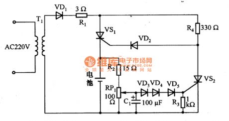
The above picture is the charger circuit of thyristor.This circuit charges nickel battery and the charging current is 1A,The charging time is 1 hour and it stops charging automatically when it is full.Because negative end of nickel-spread battery has negative temperature characteristic,VD3~VD5 forward voltage temperature characteristics compensate for it.When charging battery terminal is low voltage, the voltage on both ends of C1 are also low, thyristor VS2 stops.Thus the current flows through VD1→R1→R4→VD2→VS1 gate→VS1cathode→battery circulation and the power charges battery via VS1.
If the battery voltage rises to the voltage set by RP1, the VS2 triggers and VS1 stops. (View)
View full Circuit Diagram | Comments | Reading(2585)
Temperature Measurement Circuit One of Thermistors
Published:2011/7/11 7:45:00 Author:Michel | Keyword: Thermistors, Temperature Measurement
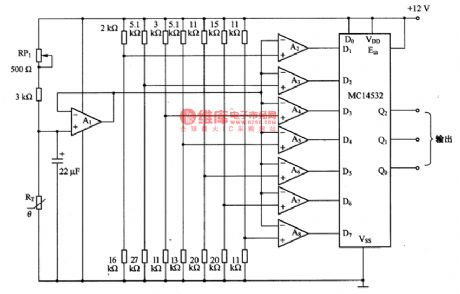
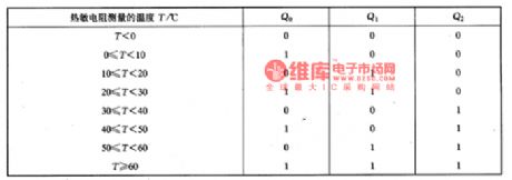
The picture is the temperature measurement circuit one of thermistors.Thermistors RT and RP1 constitute bridge road which are used to detect the different temperature. This circuit has many components but the performance is very good. Comparator A2一A8 are used to test measuring temperature range and they output 8 different temperature via MC14532 and please see the above form.
Adjusting method is as follows.30℃ 8.4 Ok Ω ordinary resistance is connected to the circuit,RP1 resistance value becomes bigger gradually from the minimum value and RP1 resistnace value is fixed and the resistance measurement precision temperature range is 土2℃ when the output code is 110一001. (View)
View full Circuit Diagram | Comments | Reading(1076)
Soft Start Control Signal Generation Circuit
Published:2011/7/11 7:42:00 Author:Michel | Keyword: Soft Start Control, Signal Generation Circuit
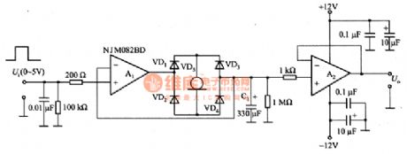
Thispiture is soft start control signal generating circuit . This circuit can be used as output voltage of power supply which is used to decrease soft start control signal and motor rotation rate control signal source of small mechanical impact. Constant output of current diodes VD5 charges and discharges C1,which gains a linear increase/decrease waveform.A1 and A2 choose small input bias current FET input type operational amplifier,NJMO82BD. The linear rise signal of the circuit is compared with the triangle waveform via comparator and it forms PWM signal.If the soft start signal is gained by changing the PWM signal dutyfactor slowly.Operational amplifiers also can choose general LF412 and AD712 etc. (View)
View full Circuit Diagram | Comments | Reading(817)
Thermometer of Transistor Temperature Sensor
Published:2011/7/11 7:40:00 Author:Michel | Keyword: Transistor Temperature Sensor, Thermometer
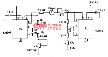
The picture is the thermometer of transistor temperature sensor. In the circuit,VT1 is transistor temperature sensor.A1 uses LM305 as voltage regulation circuit and it provides constant base current for VT1.When LM305 works in the condition that feet 6 feedback input voltage is 1.8V constantly and it is connected to VT1 base and emitter via R2 and Rz keeps the base current constant.R1/R2's change is the change of A1 output voltage.Because there is + lOmV / ℃ temperature characteristics when the output voltage of the LM305 outputs +5V and the same LM305 are used to compensate. The ammeter instruction is 0 if the RP2 is adjusted to -20℃ and the ammeter instruction is 100μA when RP1 is regulated to +80℃. (View)
View full Circuit Diagram | Comments | Reading(1322)
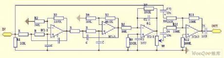
Amplitude Modulation Circuit of Analog Multiplier
Published:2011/7/11 7:39:00 Author:Michel | Keyword: Analog Multiplier, Amplitude Modulation Circuit
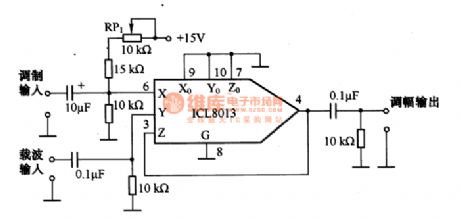
This picture is the amplitude modulation circuit of analog multiplier and it can get amplitude modulation wave through carrier signal and modulation signal multiplication.It can be widely used for general am circuit of low frequency range.ICL8013 is simulation time-multiplier monolithic integrated circuit with +10V input voltage range and it can be used asfour quadrant on time-multiplier and its output voltage,U。=Xy/l0.4 quadrant time-multiplier can be used to balance the modulation and here the bias is fixed which is used to set carrier level when there is no modulation signal.If + 5 V or-5 V bias is imposed ,it can handle + 5 V modulation signal, and then dynamic rangeis extended because handling t voltage is 0 ~ + lOV.The highest carrier signal frequency is 1OOkH and highest voltage of Y input end is 20V.2 OV signal multiplies 5V(X end input voltage) and then they divide 10 to get 10V wave attenuation. (View)
View full Circuit Diagram | Comments | Reading(2758)
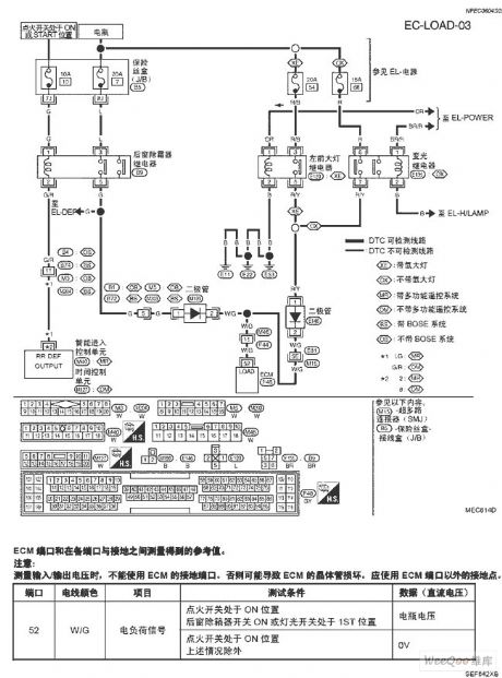
TEANA A33-EL Electrical Load Signal Circuit One
Published:2011/7/14 8:43:00 Author:Joyce | Keyword: TEANA, Electrical Load , Signal
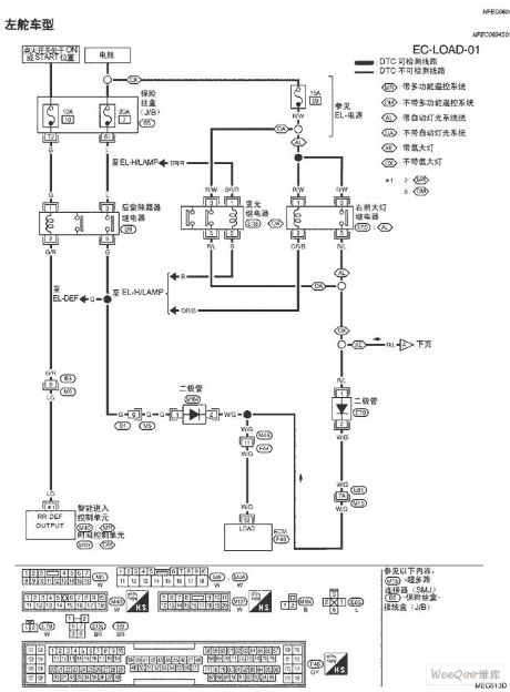
TEANA A33-EL Electrical Load Signal Circuit (View)
View full Circuit Diagram | Comments | Reading(805)
TEANA A33-EL Electrical Load Signal Circuit Two
Published:2011/7/14 8:43:00 Author:Joyce | Keyword: TEANA , Electrical Load , Signal
TEANA A33-EL Electrical Load Signal Circuit (View)
View full Circuit Diagram | Comments | Reading(848)
TEANA A33-EL Electrical Load Signal Circuit Three
Published:2011/7/14 8:43:00 Author:Joyce | Keyword: TEANA , Electrical Load , Signal
TEANA A33-EL Electrical Load Signal Circuit (View)
View full Circuit Diagram | Comments | Reading(775)
Low Power Consumption Monocell Boost Circuit
Published:2011/7/20 3:12:00 Author:Joyce | Keyword: Low Power Consumption, Monocell , Boost
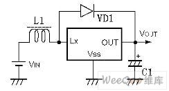
Series RH5RH / 5 RI (product of Japan Ricoh Corporation) is a boost-dedicated switching regulator for fixed output. It only needs inductance, diode and capacitance to get fixed boost output. The good feature of this circuit is that it has low power consumption (4 ~ 15 uA), and it can function properly under the circumstance of 0.9 V low input voltage
SeriesRH5RI and RH5RH are the frequency modulation model (PFM) and pulse width modulation (PWM) three-terminal boost switching regulator ICs respectively. It includes series RH5RIxx1 (RH5RHxx1) in which drive is contained within the IC and series RH5RIxx2 (RH5RHxx2) in which drive is connected externally.
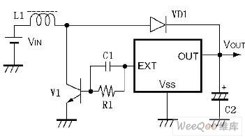
As shown in the following figure is the basic external circuit diagram of RH5RI and RH5RH.
When the drive has a large load, it can be connected externally as shown in the figure . (View)
View full Circuit Diagram | Comments | Reading(634)
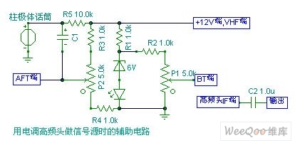
A 5W Frequency Modulation Transmitter Power Amplifier Circuit
Published:2011/7/20 3:16:00 Author:Joyce | Keyword: 5W , Frequency Modulation Transmitter, Power Amplifier

High frequency oscillation signal from output end IF of the varactor tuner of the television is used as the signal source. The tuner has a stable oscillation frequency, adding an 8 V voltage on input voltage BT would enable it to output stable frequency as long as the voltage is no less than 9 V. A coupling capacitance of several P should be added on the input end under operation. If the third stage amplifier gets too hot, two transistors should be connected with it in parallel .Adjusting the density of the inductance coil means adjusting the frequency-selecting loop.
 (View)
View full Circuit Diagram | Comments | Reading(1152)
Mega Bass Circuit
Published:2011/7/20 3:16:00 Author:Joyce | Keyword: Mega Bass
The mega bass circuit is as shown in the figure.
(View)
View full Circuit Diagram | Comments | Reading(3426)
Amplitude Modulation Circuit of Analog Switch
Published:2011/7/11 7:37:00 Author:Michel | Keyword: Analog Switch, Amplitude Modulation Circuit
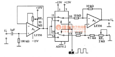
AD7512 and differential amplifiers A2 are used to complete the work. The carrier controls simulation switch and switch contact is connected to the upward side and it inputs via A2 inverse end.The modulation wave is reversed and it returns to normal phase when the next carrier wave comes and the process repeats again and again to achieve the purpose of modulation amplitude limit.It will not stop becuase of carrier cycle but only causes reversal polarity.Analog switch needs to keep up with the carrier frequency, but analog switch frequency can't be high, so the circuit can not be used in high frequency.Modulation output contains the higher harmonic square wave signal and bandpass filter should be added to get the sine wave signal. (View)
View full Circuit Diagram | Comments | Reading(1776)
TEANA A33-EL Reversing Light Circuit
Published:2011/7/14 8:40:00 Author:Joyce | Keyword: TEANA, Reversing Light
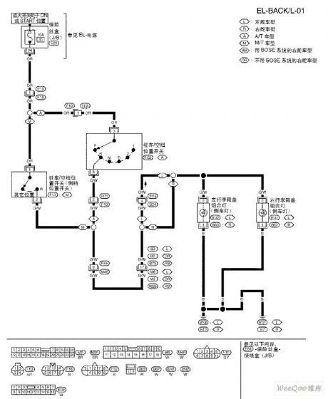
TEANA A33-EL Reversing Light Circuit (View)
View full Circuit Diagram | Comments | Reading(755)
TEANA A33-EL Stoplight Circuit One
Published:2011/7/14 8:40:00 Author:Joyce | Keyword: TEANA , Stoplight
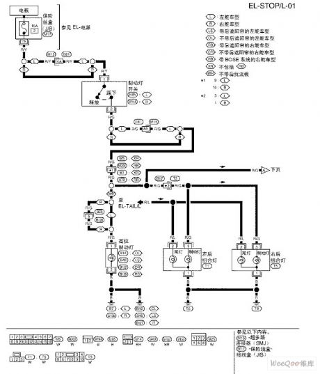
TEANA A33-EL Stoplight Circuit One (View)
View full Circuit Diagram | Comments | Reading(689)
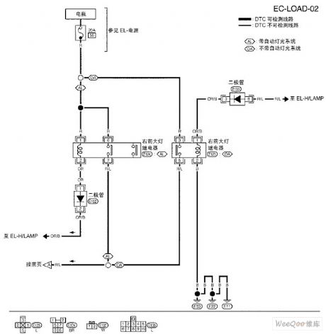
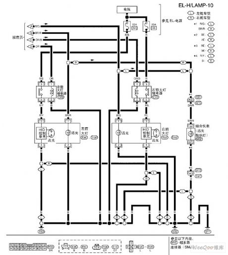
TEANA A33-EL Headlamp(Xenon) Circuit One
Published:2011/7/14 8:41:00 Author:Joyce | Keyword: TEANA , Headlamp
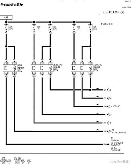
TEANA A33-EL Headlamp(Xenon) Circuit (View)
View full Circuit Diagram | Comments | Reading(697)
TEANA A33-EL Headlamp(Xenon) Circuit Two
Published:2011/7/14 8:41:00 Author:Joyce | Keyword: TEANA , Headlamp
TEANA A33-EL Headlamp(Xenon) Circuit (View)
View full Circuit Diagram | Comments | Reading(692)
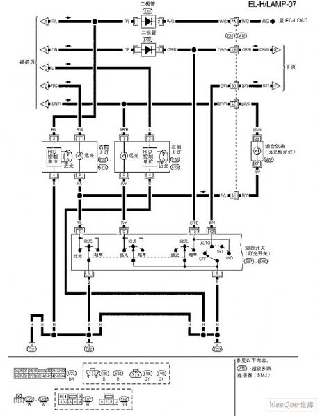
TEANA A33-EL Headlamp(Xenon) Circuit Three
Published:2011/7/14 8:41:00 Author:Joyce | Keyword: TEANA , Headlamp
TEANA A33-EL Headlamp(Xenon) Circuit (View)
View full Circuit Diagram | Comments | Reading(708)
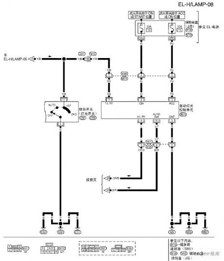
TEANA A33-EL Headlamp(Xenon) Circuit Four
Published:2011/7/14 8:42:00 Author:Joyce | Keyword: TEANA , Headlamp
TEANA A33-EL Headlamp(Xenon) Circuit (View)
View full Circuit Diagram | Comments | Reading(582)
TEANA A33-EL Headlamp(Xenon) Circuit Five
Published:2011/7/14 8:42:00 Author:Joyce | Keyword: TEANA, Headlamp
TEANA A33-EL Headlamp(Xenon) Circuit (View)
View full Circuit Diagram | Comments | Reading(736)
| Pages:1491/2234 At 2014811482148314841485148614871488148914901491149214931494149514961497149814991500Under 20 |
Circuit Categories
power supply circuit
Amplifier Circuit
Basic Circuit
LED and Light Circuit
Sensor Circuit
Signal Processing
Electrical Equipment Circuit
Control Circuit
Remote Control Circuit
A/D-D/A Converter Circuit
Audio Circuit
Measuring and Test Circuit
Communication Circuit
Computer-Related Circuit
555 Circuit
Automotive Circuit
Repairing Circuit