
Circuit Diagram
Index 1487
The constant voltage power resources circuit formed by MAX610 series AC/DC chip(no transformer)
Published:2011/7/20 22:59:00 Author:leo | Keyword: Constant voltage, no transformer
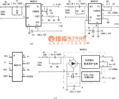
As the picture shows, this circuit is the no transformer constant voltage power resources circuit formed by MAX610 series AC/DC chip. Picture (a) is the power resources with adjustable voltage and picture (b) is power resources with extending current. MAX610 series is a type of single chip and low power DC/AC convertor which has the following features: the standard output voltage is 5 V± 0.2V and the current is 75μA with over current protection.
(View)
View full Circuit Diagram | Comments | Reading(1090)
The constant voltage power resources circuit formed by PS0500—5(No transformer)
Published:2011/7/20 22:53:00 Author:leo | Keyword: No transformer, constant voltage
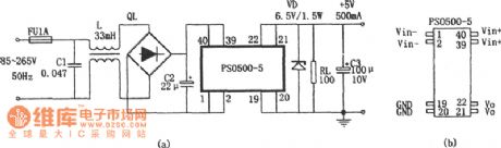
As the picture shows, this circuit is the no transformer constant voltage power resources circuit formed by PS0500-5. PS0500-5 is a 2.5 W small high frequency AC/DC converting module. It does not need power supply transformer but only outer rectifier and filter. It can offer DC voltage of 5 V and DC current of 500 mA. Its package is DIP40 with 8 ports which you can see in the picture.
(View)
View full Circuit Diagram | Comments | Reading(849)
500MA current charge,USB compatible charging management integrated circuit--CN3068
Published:2011/7/12 5:13:00 Author:chopper | Keyword: 500MA current, USB compatible, charging management, integrated circuit
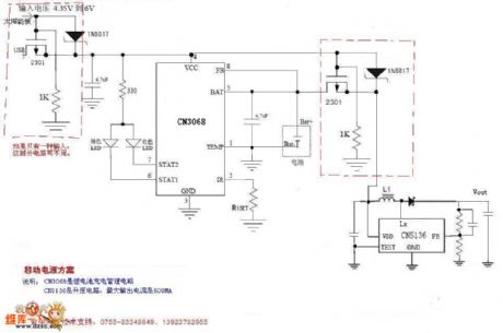
Overview :CN3068 is a charger circuit which can charge single rechargeable lithium battery in constant current/voltage mode.The device includes power transistor,and its application does not require the external current detective resistor and blocking diode.CN3069 only requires few external components,and works under USB bus technology specifications,thus it is ideal for portable applications.Heat modulation circuit can control the chip temperature within safety range if the power consumption of devices is bigger or the environmental temperature is higher. (View)
View full Circuit Diagram | Comments | Reading(2228)
Solar energy mobile solution
Published:2011/7/12 5:13:00 Author:chopper | Keyword: Solar energy, mobile solution, 6V
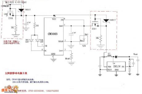
Overview :CN3083 is a single lithium battery charge management chip which can be powered with solar panels.The device includes power transistor,and its application does not require an external current detective resistor and blocking diode.The internal 8-bit analog-digital conversion circuit can automatically adjust the charge current by the current output capability of input voltage supply.Users need not consider the worst case, and it can maximize the use of the current output capability of input voltage supply.And it is suitable for the lithium battery charger application powered by voltage supply whose current output capacity is limited such as solar panel.
(View)
View full Circuit Diagram | Comments | Reading(2377)
various battery charger chips powered by solar--CN3082
Published:2011/7/12 5:12:00 Author:chopper | Keyword: battery charger chips, powered, solar, satisfy, characteristics
Overview :CN3082 is a charger control circuit which can charge various batteries like single lithium batteries,single lithium iron phosphate or two to four NiMH rechargeable batteries.The device includes power transistor,and its application does not require the external current detective resistor and blocking diode.CN3082 only requires few external components, and works under USB bus technology specifications,thus it is ideal for portable applications.Heat modulation circuit can control the chip temperature within safety range if the power consumption of devices is bigger or the environmental temperature is higher. (View)
View full Circuit Diagram | Comments | Reading(1124)
μPC1099 switching power supply circuit
Published:2011/7/11 2:34:00 Author:chopper | Keyword: switching, power supply circuit
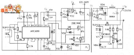
Figure shows the pPC1099 switching power supply.μPC1099 is the switching power supply integrated controller in PWM mode.And it is applied to the primary side control circuit whose main switching components adopt power MOSFET,and the main features are that:it can directly drive the power MOSFET; it is the totem-pole output circuit whose peak output current is 1.2A;it has the fast current of high-impedance;it is the over-current limiting circuit;its oscillation frequency is 50~500kHz;it has the over-voltage protection function and remote control;it uses ⑩-pin DIP and SOP packages.
(View)
View full Circuit Diagram | Comments | Reading(2096)
μPC1099 internal equivalent circuit
Published:2011/7/11 2:34:00 Author:chopper | Keyword: internal, equivalent circuit
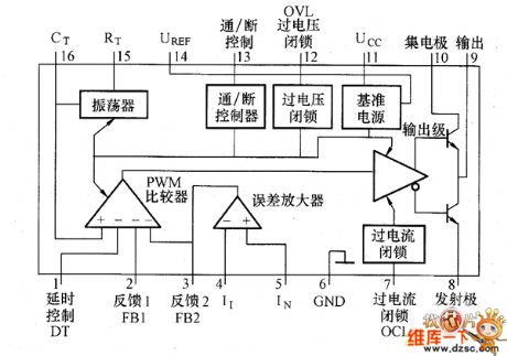
Figure shows the μPC1099 internal equivalent circuit.It consists of the reference power PWM comparator,oscillator,output pole,on/off control,over-voltage and over-current atresia part and the error amplifier.Reference power is to offer the circuits in chip the stable 5V voltage,moreover,external components will be set the maximum duty ratio,and it should be used in a feedback circuit with optical coupler.It is very important in practical application.
(View)
View full Circuit Diagram | Comments | Reading(589)
current resonant converter circuit
Published:2011/7/11 2:33:00 Author:chopper | Keyword: current, resonant converter
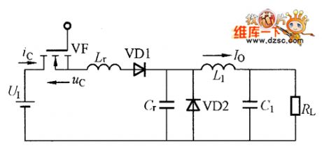
Resonant converter is the core of the soft switching power supply circuit.Resonant converters include current resonance,voltage resonance,quasi-resonance of class E,part resonance and so on.Current resonant switch is the most normal way of soft switches, and has developed a number of circuits, and has entered a practical phase.The picture shows the typical instance of current resonant converter,and it is current resonant circuit based on step-down converter.
(View)
View full Circuit Diagram | Comments | Reading(774)
oil crop screening and compaction controller
Published:2011/7/19 23:42:00 Author:chopper | Keyword: oil crop, screening, compaction controller
The oil crop(such as soybean,peanut,etc.) of rural small oil mill will be loaded to screening machine to sift through bucket conveyor before oil expression.After removing impurities,the crop will be loaded to the rolling billet machine,and then parch and squeeze the semifinished product.This example describes the oil crop screening and compaction controller,which can uses a start button to start the conveyor, screening machine and the motor of rolling billet simultaneously,and it can also choose a certain motor by controlling button.The operation is very easy. (View)
View full Circuit Diagram | Comments | Reading(637)
rice processing machine controller
Published:2011/7/19 23:42:00 Author:chopper | Keyword: rice, processing machine , controller
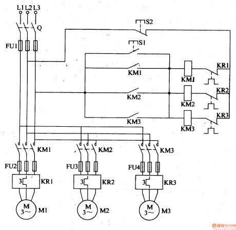
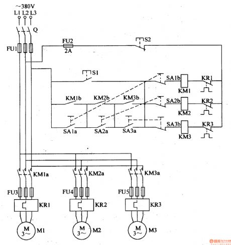
This example describes the rice processing machine controller, which uses the control button to coordinate with the AC contactor,thermal relay and other auto-electrical devices,and it can enable the automatic protection control of electric motor. The principle of circuit This rice processing machine controller circuit is formed by knife switch Q,fuses FU1-FU4, start button S1,stop button S2, AC contactors KM1-KM3 and thermal relays KR1-KR3,which is shown in Figure 4-132. (View)
View full Circuit Diagram | Comments | Reading(541)
agricultural non-tower pressure-charged water feeder(2)
Published:2011/7/19 23:41:00 Author:chopper | Keyword: agricultural, non-tower, pressure-charged, water feeder
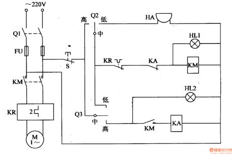
This example describes the agricultural non-tower pressure-charged water feeder,and it uses electric connecting pressure gauge as the measurement and control device.The circuit is simple, and it can cut off the power supply automatically when the water supply is not enough or the submersible pump fails to work,while the alarm sends a sound. The principle of circuit This agricultural non-tower pressure-charged water feeder circuit is formed by the knife switch Q1,fuse FU,intermediate relay KA,AC contactor KM, thermal relay KR,alarm HA, lights HL1,HL2 and the control contact of pump outlet pressure gauge Q2,control contact of tank water level testing gauge Q3, which is shown in figure 4-153.
(View)
View full Circuit Diagram | Comments | Reading(597)
greenhouse ground hotline controller(1)
Published:2011/7/19 23:40:00 Author:chopper | Keyword: greenhouse, ground hotline, controller
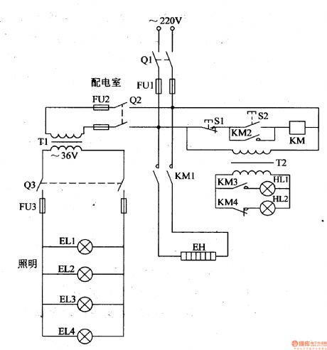
In the northern winter and spring, farmers usually lays the ground hotline to assist warming in order to increase the temperature inside the greenhouse,and promote the growth of seedlings,vegetables.Here is a ground hotline controller of common-used single-phase power for installation reference. The principle of circuitThis greenhouse ground hotline controller circuit is formed by the control circuit,working status indication circuit and low voltage lighting circuit, which is shown in figure 4-198.
(View)
View full Circuit Diagram | Comments | Reading(595)
greenhouse ground hotline controller(2)
Published:2011/7/19 23:38:00 Author:chopper | Keyword: greenhouse, ground hotline, controller
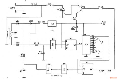
This example describes the greenhouse ground hotline controller, which uses the cycle rate control,and it is of advantages like energy saving, small harmonic interference and so on. The principle of circuitThe greenhouse ground hotline controller circuit is formed by power supply circuit and heating control circuit, which is shown in figure 4-199. Power supply circuit is formed by the fuse FU,power transformer T,rectifier diodes VD1-VD3, resistor R1,three-terminal voltage regulator integrated circuit IC1 and filter capacitor C1. Heating control circuit consists of resistors R2-R5,capacitor C2,voltage regulator diode VS,non-gate Schmitt trigger integrated circuit IC2 (D1-D3), trigger JK integrated circuit IC3 (A1,A2,counting/pulse distribution integrated circuit IC4, selective switch S,the transistor V,thyristor VT and ground hotline EH.
(View)
View full Circuit Diagram | Comments | Reading(1013)
seedlings growth stimulator in seedling house
Published:2011/7/19 23:20:00 Author:chopper | Keyword: seedlings, growth stimulator
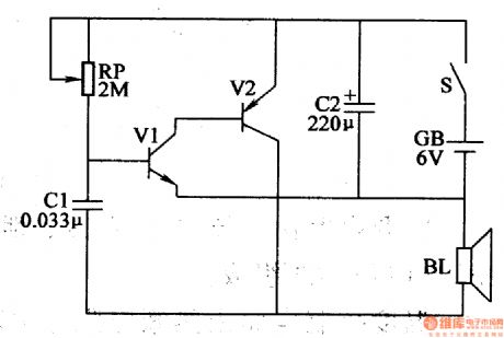
This example describes the seedlings growth stimulator in seedling house,and it is set in the middle of the seedling house which is based on that plants are more sensitive to low-frequency pulse.Thus,users can stimulate the seedlings with its low-frequency pulse,and promote the growth of seedlings.Users can test a small area first, and then put into operation based on the practical situation. The principle of circuitThis seedlings growth stimulator circuit consists of transistors V1,V2,potentiometer RP,capacitors C1,C2,speaker BL,battery GB and power supply switch S which is shown in figure 4-209.
(View)
View full Circuit Diagram | Comments | Reading(609)
wire break informing device of rural cablecasting circuit
Published:2011/7/19 23:37:00 Author:chopper | Keyword: cablecasting, wire break, informing device
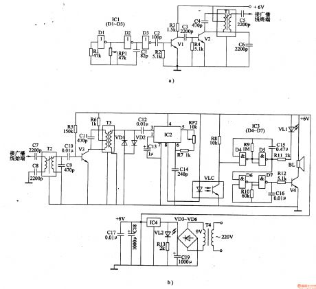
The principle of circuitThe wire break informing device of rural cablecasting circuit is formed by the carrier transmitter circuit,the carrier receiving circuit, alarm circuit and power supply circuit,which is shown in figure 4-212. Carrier transmitter circuit (installed in the terminal of cable broadcasting line) is formed by the high-frequency oscillator and amplified output circuit.The high-frequency oscillator is formed by non-gate D1,D2,resistor R1,capacitor C1 and potentiometer RP1 which are in the non-gate integrated circuit IC1 (D1-D3);and the amplified output circuit is formed by the non-gate D3,capacitors C2-C6,transistor V1,V2,resistors R2, R3 and intermediate-frequency transformer T1 that are in the non-gate D3.
(View)
View full Circuit Diagram | Comments | Reading(873)
motor headlight auto-changing controller(II)
Published:2011/7/19 23:36:00 Author:chopper | Keyword: motor, headlight, auto-changing controller
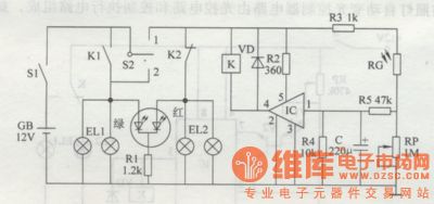
Principle of the circuit The motor headlight auto-changing controller circuit is formed by the optical detection circuit,control implementation circuit and LED indication which is shown in figure 7-2. Photoelectric detection circuit is formed by the photosensitive resistor RG,resistors R3-R5,capacitor C and the potentiometer RP. Control implementation ircuit is formed by the electronic switching integrated circuit IC,resistor R2,diode VD and relay K. LED indication circuit is formed by resistors Rl and color-changing light-emitting diode VL. S1 is the switch of vehicle key, S2 is the vehicle switch of turn light.
(View)
View full Circuit Diagram | Comments | Reading(607)
headlamp delay shutoff device
Published:2011/7/14 20:44:00 Author:chopper | Keyword: headlamp, delay shutoff
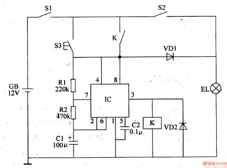
This example describes the headlamp delay shutoff device, and the headlamps can continue lighting a period of time before they close automatically when drivers press the delay button,thus it can offer a short time emergency lighting when the drivers park and leave in the night. The principle of circuit The headlamp delay shutoff device circuit includes the delay button S3,resistors R1,R2,capacitor C1,C2,diode VD1,VD2, relay K and time-base integrated circuit IC,which is shown in figure 7-32 . EL is the motor headlamp,S1 is the total power switch for the automotive,and S2 is the headlamp switch.
(View)
View full Circuit Diagram | Comments | Reading(712)
motor headlamp auto-changing controller(3)
Published:2011/7/19 23:36:00 Author:chopper | Keyword: motor, headlamp, auto-changing controller
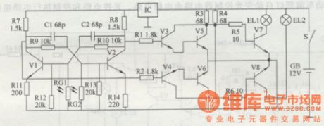
According to traffic safety rules,it should open high beam (bright light) when motors drive at night,but it should open low beam(weak light) when motors meet.Thus,drivers sholuld control the operation light by hands or feet several times when it meets at every time.This example describes motor headlamp auto-changing controller produced by discrete components,and it can automatically transform the high beam and low beam of motor when the motors meet to decrease the intensity of labour of drivers,and ensure safety. The principle of circuit The controller circuit consists of bistable trigger circuit and switching control circuit,which is shown in figure 7-3.
(View)
View full Circuit Diagram | Comments | Reading(713)
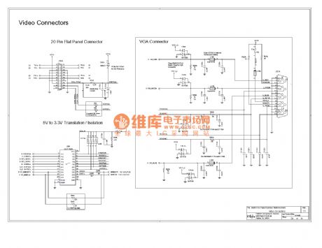
Computer motherboard circuit 810 4_23
Published:2011/7/22 2:29:00 Author:Ecco | Keyword: Computer motherboard
View full Circuit Diagram | Comments | Reading(490)
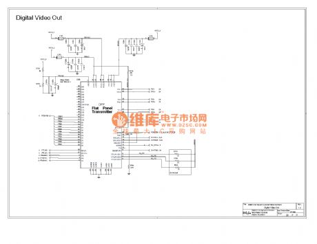
Computer motherboard circuit 810 4_24
Published:2011/7/22 2:30:00 Author:Ecco | Keyword: Computer motherboard
View full Circuit Diagram | Comments | Reading(557)
| Pages:1487/2234 At 2014811482148314841485148614871488148914901491149214931494149514961497149814991500Under 20 |
Circuit Categories
power supply circuit
Amplifier Circuit
Basic Circuit
LED and Light Circuit
Sensor Circuit
Signal Processing
Electrical Equipment Circuit
Control Circuit
Remote Control Circuit
A/D-D/A Converter Circuit
Audio Circuit
Measuring and Test Circuit
Communication Circuit
Computer-Related Circuit
555 Circuit
Automotive Circuit
Repairing Circuit