
Circuit Diagram
Index 1495
DC Motor Stepless Speed Governor Circuit
Published:2011/7/13 7:32:00 Author:Michel | Keyword: Speed Governor Circuit
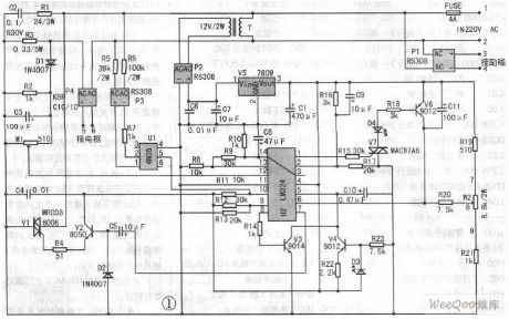
This circuit board circuit is simple, its cost is not high and it is easy to make.The following is simple analysis of the circuit.220 V AC steps down when it flows through transformer T, the P2 rectifier voltage,P2 retifies and V5 constant voltage gets 9V DC voltage and it provides four operational amplifier intergrated chips LM324(Click and Check:four operational amplifier chip LM124 / LM224 / LM324 Chinese material ).P1 rectifier output provides DC motor excitation power supply.P4 rectification gets 0-200V DC by silicon control and realizes motor 0-time speed by connecting motor armature.R1 and C2 are resistance components and they protect controlled silicon. (View)
View full Circuit Diagram | Comments | Reading(1696)
Electronic transformer
Published:2011/7/13 23:13:00 Author:TaoXi | Keyword: Electronic transformer
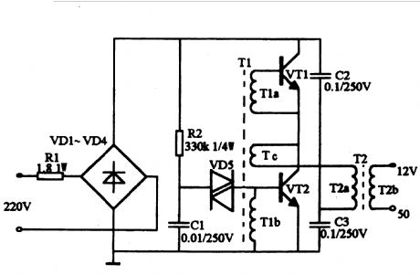
The circuit is as shown. The operating principle is the same as the switching power supply, the diodes VD1~VD4 forms the rectifier bridge and this rectifier bridge changes the city electricity into the DC, the high frequency oscillation circuit is copmosed of the oscillation transformer T1, the transistors VT1 and VT2, and this high frequency oscillation circuit changes the pulse DC into the high-frequency current, then the high-frequency high-voltage pulse is reduced by the ferrite output transformer T2 to get the voltage and power. R1 is the current limiting resistor. The start trigger circuit is composed of the resistance R2, the capacitance C1 and the two-way trigger diode VD5. The transistors VT1 and VT2 use the S13005, the B is 15~20 times. Also you can use the BUceo>=35OV high power transistor such as the C3093.
(View)
View full Circuit Diagram | Comments | Reading(4495)
Fixed DC Power Supply Diagram3
Published:2011/5/20 3:10:00 Author:Nora | Keyword: Fixed, DC , Power
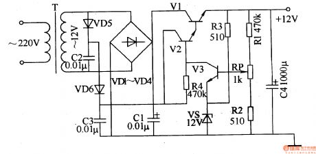
AC 220V step-down voltage by T in T, to generate AC 12V secondary winding voltage, the voltage all the way through VDl-VD4 bridge rectifier, Cl Vl filter Bo Houjia to the collector on; another path VD5, VD6 and C2 , C3 times the pressure of the rectified voltage to provide work for the V2. V2 turn, its output voltage of the emitter turn-Vl, the output from the Vl + l2V emitter voltage. When Vl emitter output voltage when the high side at + l2V, V3 conduction capacity enhancement, so that the base voltage V2 goes low, Vl and V2 in the conduction diminished capacity, the output voltage down to normal; when Vl emitter When the output voltage is low, V3 conduction diminished capacity, V2 increase the base voltage, so that Vl and V2 in the conduction capacity enhancement, the output voltage to normal.
(View)
View full Circuit Diagram | Comments | Reading(744)
Assembly of the electronic type energy-saving lamp
Published:2011/7/13 23:13:00 Author:TaoXi | Keyword: Assembly, electronic type, energy-saving lamp

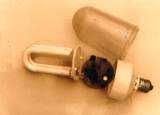

Operating principle: in the moment of the power is connected, the power voltage adds to the two ends of the trigger and light bulb through the ballast, when the light bulb does not light, the circuit is in the open state. The trigger begins to work immediately with the power voltage, and it produces the pulse high voltage that is higher than 3KV to add to both ends of the bulb L, this voltage activates the normal temperature elements of the bulb L into the gas, and the voltage breaks through the gas, L is in the low resistance high current state, so the voltage of the bulb L reduces, it is about 30-50V, the trigger stops working because the voltage is too low. The whole starter process is about 0.8 second.
(View)
View full Circuit Diagram | Comments | Reading(488)
High power factor, high efficiency electronic ballast controller ML4831
Published:2011/7/13 23:14:00 Author:TaoXi | Keyword: High power factor, high efficiency, electronic ballast, controller
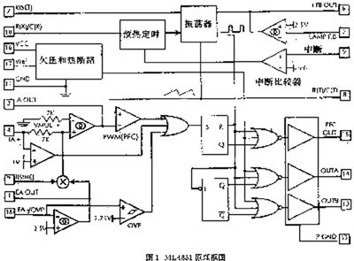
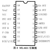
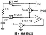
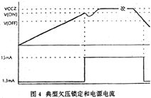
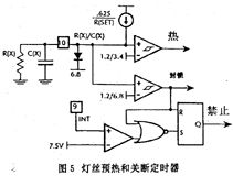
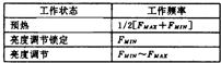
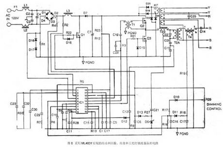
The ML4831 is designed as one kind of brightness adjustable high power factor, high efficiency electronic ballast controller. It is composed of the power factor controller, the oscillator, the preheat turn-off timing sequence, the control selective passing logic, the output driver and the over-voltage, over-temperature protection devices. The restarting and the lamp re-exporting are controlled by the external timing sequence, and considering the comprehensive control of the different tube characteristics, the ballast control device can adjust the lamp power through the frequency modulation (FM), it adjusts the lamp power and the operating frequency of the voltage-controlled oscillator (VCO) by compensating the programming. These functions are integrated on one chip, so this chip can be used in different occasions.
(View)
View full Circuit Diagram | Comments | Reading(1076)
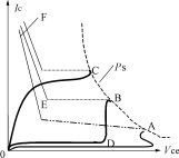
Selection guides of the energy-saving lamps and electronic ballast transistor parameters
Published:2011/7/13 23:15:00 Author:TaoXi | Keyword: Selection guides, energy-saving lamps, electronic ballast, transistor, parameters
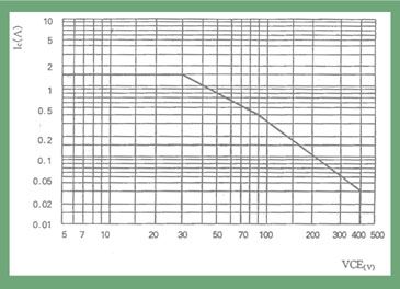
The power tolerance is a area which is surrounded by the curve (figure 1), when the voltage and current coordinate values of the transistor are over the range of the curve, the transistor will occur the power breakdown and it will be damaged. In practical applications, some switching power supply line loads are sensitivity, after the transistor is cut off, the self-inductance potential anti-peak voltage which is produced by the inductive load adds between the C pole and E pole of the transistor, so the transistor need to have enough SOA, BVceo and BVcbo values to bear the back voltage.
(View)
View full Circuit Diagram | Comments | Reading(590)
Single Power Complementary and Symmetry Power Amplifier Circuit
Published:2011/7/13 7:21:00 Author:Michel | Keyword: Single Power, Complementary and Symmetry, Power Amplifier Circuit

First,the circuit structure and principleFigure 1 is a circuit uses power complementary and symmetry principle.The T3 constitutes preamplifier stage and T2 and T1 constithute complementaryand symmetry circuit output.When input signal vi=0,usually IC3 ,VB2 and VB1 reach needed value as long as both numerical valueof R1 and R2 are proper.At the time,T2 and T1 are provided a proper offset section,so that the electric potential of K2,VK is equlal to VC and VCC/2.
When the signal vi is added,T1 conducts the electricity ,current flows through load RL and C is charged as the signal is on its negative half cycle.When it's positive half cycle,T2 conducts the electricity,the charged capacitance C acts acts as a double power as power supply -VCC and it discharges via load RL. (View)
View full Circuit Diagram | Comments | Reading(690)
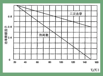
Energy-saving lamps power tube failure mechanism analysis
Published:2011/7/13 23:16:00 Author:TaoXi | Keyword: Energy-saving lamps, power tube, failure, mechanism, analysis
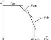
From the failure mechanism analysis, we know that in order to reduce the failure, we need to reduce the operating power of the tube and improve the secondary breakdown characteristic, in fact, the two are related. By the mechanism of the secondary breakdown, we know that the temperature rise increases the tube's HFE and switching performance becomes poor, also the secondary breakdown characteristic; the rise of temperature makes the actual dissipation power parameter become poor, the safe operating area of the tube becomes smaller. vice versa. So in order to improve the quality of the tube, we need to prevent the over-temperature of the tube when it is operating and improve the dissipation power.
(View)
View full Circuit Diagram | Comments | Reading(525)
The applications of the full-bridge driver UBA2030T
Published:2011/7/13 23:17:00 Author:TaoXi | Keyword: applications, full-bridge, driver
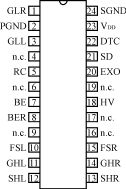
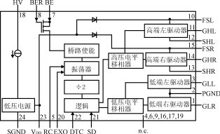
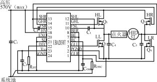
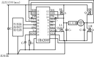
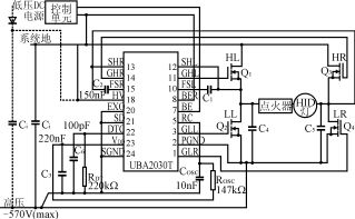
The PHILIPS company uses the BCD750 power logic process method to produce the UBA2030T, this device is designed as one kind of high-voltage IC that can be used to drive the power MOSFET of the full-bridge topology structure. The UBA2030T only needs to use a small amount of the external components to form the high strength discharge (HID) lamp electronic ballast circuit, and it supplies the solution for the design of the HID lamp driving circuit.
The UBA2030T uses the 24-pin SO package which is as shown in figure 1.
The UBA2030T is composed of the bootstrap diode, the oscillator, the high-voltage and low-voltage electrical level phase shifter, the high-end and low-end drives and the control logic circuit. The internal structure block diagram is as shown in figure 2.
(View)
View full Circuit Diagram | Comments | Reading(1056)
Unattended storage battery automatic power supply device circuit
Published:2011/7/14 22:17:00 Author:TaoXi | Keyword: Unattended, storage battery
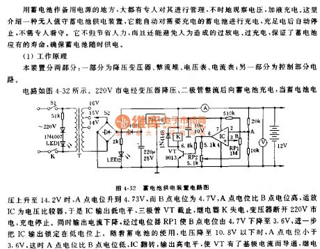
The operating principle:
This device has two parts: one part is composed of the step-down transformer, the rectifier stack, the voltmeter, the ammeter; another part is the control part.
The circuit is as shown in figure 4-32. The 220V city electricity is reduced by the transformer and is rectified by the diode to charge the storage battery, when the voltage of storage battery increases to 14.2V, the potential of A point is 4.37V, the potential of B point is 4.7V, the potential of A point is higher than the B point, the op-amp IC is the voltage comparator, so the IC outputs the low level, the transistor VT cuts off, the relay K loses the electric and the transformer disconnected the 220V city electricity, the charging stops.
(View)
View full Circuit Diagram | Comments | Reading(673)
Boost DC-DC Converter Circuit of HS7076
Published:2011/7/13 8:23:00 Author:Michel | Keyword: DC-DC, Converter Circuit
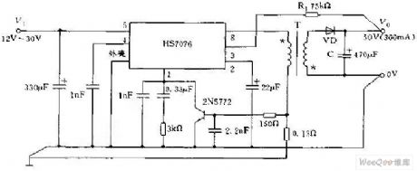
The transformer coupling DC-DC converter shown in the picture is composed of HS7076.The converter's input voltage,output voltage and output current are 15-30V,50V and 300mA respectively.When the circuit works normally, stabilizer conducts,primary transformer flows through current and stores energy,subprime voltage make rectifier diode stop.At the time,output capacitance C discharges to load and the primary electroless diode of transformer stops when the regulator stops. (View)
View full Circuit Diagram | Comments | Reading(728)
9W Audio Power Amplifying Circuit of μPC2002
Published:2011/7/13 8:22:00 Author:Michel | Keyword: 9W Audio Power, Amplifying Circuit
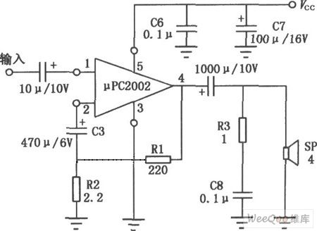
μPC2002 is audio power amplifying IC and it uses 5 feets single in-line plastic package and its pin's shape is divided into H and V type.This circuit output power is large and its distoration is small,the noise is low and the impulsive sound is low when it starts up. It also has surge-protector of the power supply,over-voltage and short-circuit overload protection. Thus it's widely used in car stereos, audio power amplifier of recorders.And its typical application circuit is shown as above. (View)
View full Circuit Diagram | Comments | Reading(1432)
Doppler Microwave Automatic Switch Circuit
Published:2011/7/13 7:17:00 Author:Michel | Keyword: Doppler Microwave, Automatic Switch Circuit
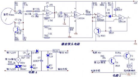
Microwave automatic switch controls the circuit according to microwave doppler effect and it can monitor moving objects and change the moving into electrical signals to control the electric light bulb or electronic appliances opening and closing.
Working principle is same as the following oscillating circuit composed of antenna,T1 and C5.The antenna radiates to the space and it produces a microwave field radius if someone or object in microwave field, which will cause the mobile microwave frequency with about 10 m radius.It will causes microwave frequency shift if someboday or some object moves in the field.In the circuit,it embodies in the change of the voltage of the antenna, C4 will couple this change to the op-amp AD amplification, op-amp output AD forms voltage on R6, when it flows through C2.The voltage's highness and lowliness are relevant to the object distance and moving speed and it's usually between 0-3V.Op-amp AA connects to comparator,it's 0.4V when the reference voltage is 12V. (View)
View full Circuit Diagram | Comments | Reading(2615)
Phase Detection and Double Direction Counting Circuit of EPC-755A
Published:2011/7/13 7:08:00 Author:Michel | Keyword: Phase Detection, Double DirectionCounting, Circuit

EPC-755A photoelectric encoder has good performance and has good anti-interference in angle and displacement measuring.EPC-755A photoelectric encode also owns stable and reliable output pulse signal, and the pulse signal can be obtained after the count is measured in digital signal.On the steering wheel rotation angle measurement EPC-755 A photoelectric encoder is chosen as sensor when we develop a driving simulator in the car.Its output circuit chooses open collector and output resolution selects 360 pieces of pulses/circles,which can be clockwise and counterclockwise,considering the steering wheel rotation is bidirectional,and it can be counted after detecting the output signal of the encoder. (View)
View full Circuit Diagram | Comments | Reading(1127)
Three-phase and Six-step Motor Control Circuit of MC33035
Published:2011/7/13 7:06:00 Author:Michel | Keyword: Three-phase, Six-step, Motor Control Circuit
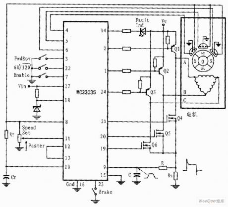
The shown three-phase application circuit owns motor controller circuit connection diagram which is driven by full wave six-step.The power switch triode is Darlington PNP type and the lower power switch triode is N groove power MOSFET. Each device contains a parasitic catching diode thus it can make stator inductance energy return power supply.The output can drive triangle or star connecting stators.The neutral grounded Y connection can be driven if the split power is used.
In any given rotor position,the circuit shown in picture 3 only has an effective top and bottom power switch(They belong to different totem columns). (View)
View full Circuit Diagram | Comments | Reading(7198)
Infrared remote control circuits TR1300/1315 and PIC12043
Published:2011/7/18 21:48:00 Author:TaoXi | Keyword: Infrared remote control
The same to the digital coding circuit, the output coding of the jump yards coding circuit can be transmited by the infrared or radio waves. The modulation signal is amplified and demodulated by the receiving circuit and demodulating circuit at the receiving port, and this signal is sent out by the jump yards decoder chip, it controls the corresponding circuit by controlling the executive circuit. The infrared remote control circuit which is composed of the jump yards chip TR1300/1315 and the infrared remote control receiving module PIC12043 is as shown:
Infrared receiving demodulation decoding and output circuit:
(View)
View full Circuit Diagram | Comments | Reading(1012)
Threshold Switch Circuit of TCAl05 or TCA205A
Published:2011/7/13 7:07:00 Author:Michel | Keyword: Threshold, Switch Circuit
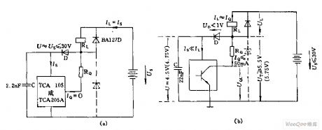
Shown as the above picture,the highest voltage of circuit (a) has risen to 30V from Us=4.5V(When TCA105 is used) or 4.75 (When TCA205A is used).
Here load is relay coil.The load current is 3mA in blocking state and it's load currentinconducting state,. (View)
View full Circuit Diagram | Comments | Reading(1069)
MAX8596Z Switching Regulator Driving Eight White LED Circuit
Published:2011/7/11 23:33:00 Author:Michel | Keyword: White LED Circuit
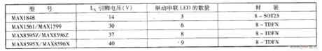
When the series white LED are driven,the LED can get homogeneous brightness because the flowing current is equal.The defect of driving voltage is that driving voltage is the sum of each LED postive voltage.The driver's ouput voltage amplitude should satisfy the series LED driving voltage.This series configuration needs to use inductive boost switch converter, in order to obtain high efficiency when it's high voltage.When we choose this type of converter,LX pins rated output voltage should be taken into consideration.
The table gives a few rated voltage of inductive boost switch converter Lx pins and drivable series white LED numbers. (View)
View full Circuit Diagram | Comments | Reading(531)
Basic Circuit of Switch Power Drive LED Array
Published:2011/7/11 23:37:00 Author:Michel | Keyword: LED Array, Basic Circuit
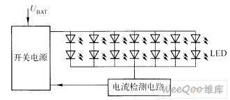
Usually the driver provides over 25W power when automobiles' front lights use white LED blacklight.Because one advantage of white LED components is high efficiency and drive electronic components should also improve efficiency, so as to play the advantages of white LED technology fully.The switch power drive white LED array circuit is showed as above.
Picture:Basic Circuit of Switch Power Drive LED
(View)
View full Circuit Diagram | Comments | Reading(673)
Super-regenerative receiver module CS902 can be used with the emission component CS901
Published:2011/7/18 21:49:00 Author:TaoXi | Keyword: Super-regenerative receiveremission component
The antenna receives the emission signal and makes the signal get through the filter that is composed of the L1 and C1, so the 315Hz signal gets the maximum gain. The receiving signal is amplified by the high frequency amplifier which is composed of VT1, so the receiving signal has the larger signal amplitude. The signal of VT1 gets into the super-regenerative detector circuit which is composed of the VT2, L0, C7 and C7, C10.etc to be detected. The output detection signal of the VT2 is amplified by the two-stage amplifier which is composed of the LM358 dual op-amp circuit, then it is sent out to the digital decoder from the output port.
(View)
View full Circuit Diagram | Comments | Reading(1108)
| Pages:1495/2234 At 2014811482148314841485148614871488148914901491149214931494149514961497149814991500Under 20 |
Circuit Categories
power supply circuit
Amplifier Circuit
Basic Circuit
LED and Light Circuit
Sensor Circuit
Signal Processing
Electrical Equipment Circuit
Control Circuit
Remote Control Circuit
A/D-D/A Converter Circuit
Audio Circuit
Measuring and Test Circuit
Communication Circuit
Computer-Related Circuit
555 Circuit
Automotive Circuit
Repairing Circuit