
Circuit Diagram
Index 1499
Auto-dimming lamp circuit diagram
Published:2011/7/20 20:13:00 Author:Ecco | Keyword: Auto-dimming, lamp
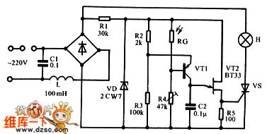
The circuit is shown as the chart. AC voltage is rectified by the bridge pile, of which one way is stabilized by stabilovolt tube VD through R1 to provide 9V pulse DC voltage for control circuit; another way is added to the light H and SCR VS. Change the conduction angle of VS can change the brightness of light H; the currrent through H is the pulsating DC current. The control circuit uses the pulsating DC current to ensure the output trigger pulse and anode voltage of SCR VS be synchronization.
(View)
View full Circuit Diagram | Comments | Reading(986)
Four-way independent touch switch circuit
Published:2011/5/13 3:54:00 Author:Nicole | Keyword: touch switch
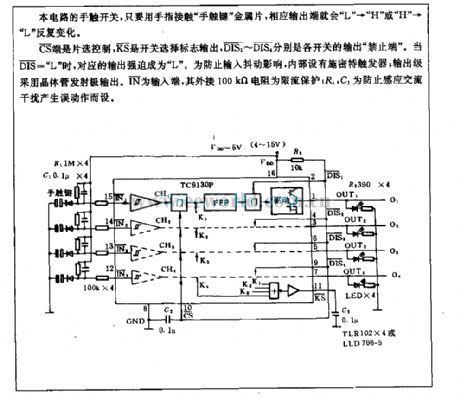
The touch switch of this circuit, if the finger touches the finger touch key metal plate, the output terminal will repeatedly change with L to H or H to L .
CS terminal is chip selection control, KS is switch selection sign output, DIS1~DIS4 are the output prohibition terminal of each switch. When DIS= L , the corresponding output is forced to be L . In order to prevent the input jitter influence, it contains inside Schmidt trigger; the output level adopts transistor emitter to output. IN is input terminal; the external 100kΩ resistance is limit current protection; R1, C1 is used to prevent the induction AC interference. (View)
View full Circuit Diagram | Comments | Reading(1040)
Water tank water level alarm circuit
Published:2011/5/13 3:50:00 Author:Nicole | Keyword: water level, water tank
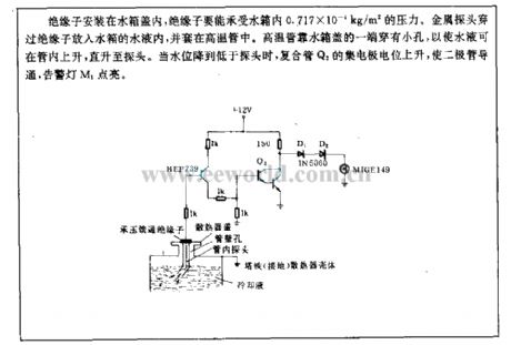
The insulator is fixed in water tank cap, the insulator should bear 0.717*0.001 kg/m2 pressure. The metal detectorpasses the insulator then it is put into water, and it is covered with high temperature tube. One terminal of the high temperature tube which is close to water tank cap has a little hole, it can make the water rise in the tube, even rise to the probe. When the level is lowed than probe, the collector potential of composite pipe Q2 will rise, then the diode turns on, alarm light M1 is lighting. (View)
View full Circuit Diagram | Comments | Reading(801)
Opto-electrical control circuit applied to four-work unite machine
Published:2011/5/13 3:49:00 Author:Nicole | Keyword: opto-electrical control, four-work unite machine
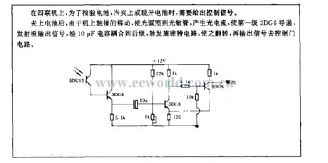
After the battery is clipped, because the movement of touch stick will make the light source shine to photosensitive tube, and produce light current, the first level 3DG6 turns on, the emitter outputs signal, the singal is coupled to back level by 10μF capacitance, Schmitt circuit is triggered and flipped, it outputs singal to control the gate circuit. (View)
View full Circuit Diagram | Comments | Reading(563)
Double relay 100~200W automatical regulator analysis
Published:2011/5/2 7:23:00 Author:Nicole | Keyword: relay, 100~200W automatical regulator
The principles of circuit: the power grid is connected to 3 foot of transformerB by switch, J1's normally closed contact. R1 is sample transistance, the control circuit is composed of BG1, BG2, it can change the control point by adjusting W. When the power grid is lower than 220V, J1 normally closed contact changes the transformer B into boost type. If the output voltage does not exceed 220V, J2 normally closed contact connects to transformer 5 foot. If it is higher than 220V, J2 pulls in and connects to transformer 4 foot. If the power grid is higher than 220V, it controls J1 to pull in by R1 sample, it is connected to transformer 5 foot, then it willform buck type. If output terminal voltage exceeds the set value, then to control J2 pull in by R4 sample, the normally open contact is connected to 4 foot. The selection of components: regulator power depends on the transformer iron core section and enameled wire diameter. The iron chip can use 19×(24~25), the coil adopts 0.27~0.35 high strength enamelled wire to close winding, it should not use packing paper between layers. 1~2 should go around 48 turns, 2~3 should go around 822 turns, from the third foot it uses 0.41~0.51 enamelled wire, 3~4, 4~5 all go around 85 turns. BG1, BG3 chooses 3DG small power tube, BG2, BG4 use PNP silicon middle power tube. There is no special requirements for resistance capacitance. (View)
View full Circuit Diagram | Comments | Reading(544)
NC Lathe detection circuit
Published:2011/5/13 3:45:00 Author:Nicole | Keyword: NC Lathe
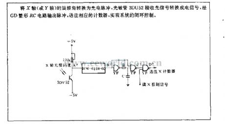
The rotation angle of X axis(or Y axis) is transformed into photoelectric pulse, photosensitive tube 3DU52 receives optical signal then change into electrical signal, RC circuit output pulse reshaped byGD , sending to the counter, to achieve the system closed loop control. (View)
View full Circuit Diagram | Comments | Reading(663)
LED extinguishment circuit
Published:2011/5/13 3:42:00 Author:Nicole | Keyword: LED
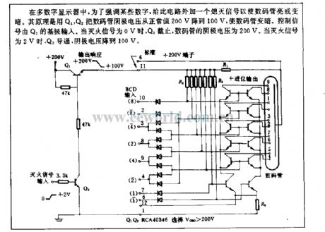
In multi-digital display, in order to stress some numbers, so a black out signal is added to this circuit, then the LED will brighten or darken. The principle: LED cathode voltage is dropped from 200V to 100V by Q1, Q2, LED will draken. Control singal is outputed by Q2 base. When the fire extinguishment singal is 0V, Q2 cuts off, LED cathode voltage is 200V. When the fire extinguishment singal is 2V, Q2 turns on, cathode voltage drops to 100V. (View)
View full Circuit Diagram | Comments | Reading(578)
Digital velocity detection circuit
Published:2011/5/13 3:33:00 Author:Nicole | Keyword: digital velocity detection
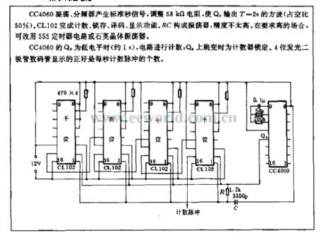
CC4060 oscillation, frequency divider produces standard second signal, to adjust 58kΩ resistance, to make Q9 outputs T=2s square wave(duty cycle is 50%). CL102 completes counting, latch, decoding, display function. RC forms oscillator, but the precision is not high. In demanding occasion, we can use 555 timer circuit or quartz crystal oscillator.
When Q9 of CC4060 is low level(about 1s), the circuit starts to count; when Q9 isjumping, the timer is latched. 4 bits LED displays the number of count pulse per second. (View)
View full Circuit Diagram | Comments | Reading(810)
A circuit using the reflected light of photoconductive LED to detect displacement
Published:2011/7/6 20:17:00 Author:zj | Keyword: reflected light, photoconductive LED, detect displacement
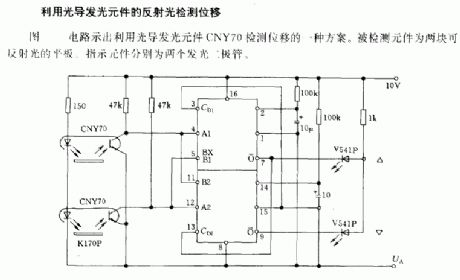
A circuit which uses the reflected light of photoconductive LED to detect displacement.The circuit diagram shows a program which uses the reflected light of photoconductive LED CNY70 to detect displacement.The detected diodes are two reflective flats.The indicating devices are two LED. (View)
View full Circuit Diagram | Comments | Reading(1367)
Digital display multifunction thermometer circuit
Published:2011/5/13 3:11:00 Author:Nicole | Keyword: Digital display, multifunction thermometer
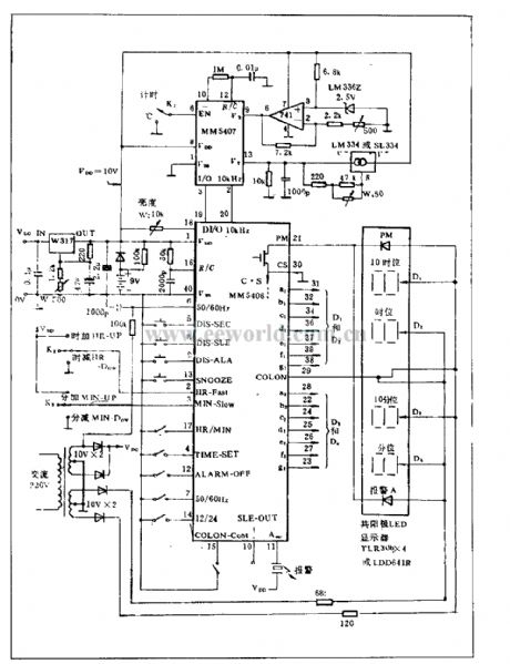
The functions of this circuit are: alarm, display, timing, digital display and temperature display. MM5406 is the part of clock, it is PMOS IC, 40-foot packaging, its functions include: alarm, stop alarming, sleep, 12/24h time selection, second display, fast set h, slow set min, 50/60Hz clock selection.
MM5407 is thermometer used IC, the temperature range is -40~+88℃, the temperature sensor uses LM334 or SL334, the temperature factor is 10mV/℃, it can be adjusted by W4.
This circuit has 9V spare battery. When the AC power is cut off, this battery is used as power supply, then the time clock works normally, but LED will be turned off due to the power failure. (View)
View full Circuit Diagram | Comments | Reading(1040)
Circuit of using solar to charge to battery
Published:2011/5/13 3:07:00 Author:Nicole | Keyword: solar, battery
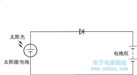

The output current of solar battery is influenced by weather condition:
(View)
View full Circuit Diagram | Comments | Reading(626)
Bar code singal regulating circuit
Published:2011/5/13 3:04:00 Author:Nicole | Keyword: bar code, singal regulating
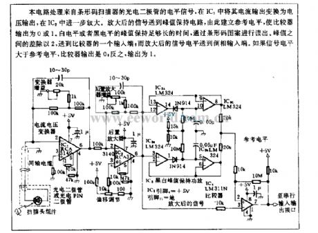
This circuit is used to handle the level singal from bar code scanner photodiode, it can change the current output into voltage output in IC1, then it is further amplified by IC2. Amplificative singal is sent to peak value hold circuit, then it will build a reference level, the comparator output is 0 or 1. The peak value of white level or black level should keep long time enough, then it will be read-out by bar code pattern. The difference between peak value is divided by 2 then transported to a output terminal of comparator; and the amplificative singal level is transported to phase reversal inout terminal. If the singal level is higher than reference level, the comparator output is 0, contrarily, the output is 1. (View)
View full Circuit Diagram | Comments | Reading(899)
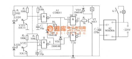
Infrared reflecting automatic lamp circuit(TX05D)
Published:2011/7/4 2:48:00 Author:zj | Keyword: Infrared reflecting, automatic lamp
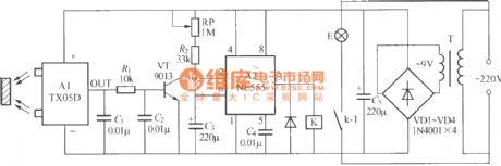
As the diagram shows it is a practical infrared reflecting automatic lamp circuit. When you go closely to it,the lamp lights up.When you leave, the lamp goes out. It can be used for home storage room, bathroom lighting or dresser mirror front lamps and other occasions. (View)
View full Circuit Diagram | Comments | Reading(565)
Infrared remote control lamp switch circuit (2)
Published:2011/7/4 2:52:00 Author:zj | Keyword: Infrared remote control, lamp switch circuit (2)
As shown in the figure, circuit (a ) is an infrared light emitter circuit, the oscillation frequency is 20kHz; ( b) is an infrared light receiver circuit and K uses static power consumption memory self-locking relay ( DC5V ZS-01 ). (View)
View full Circuit Diagram | Comments | Reading(1096)
Infrared remote control dimmer lamp circuit
Published:2011/7/4 2:54:00 Author:zj | Keyword: Infrared remote control dimmer lamp circuit
Infrared ray emitter circuit:
Infrared ray receiving controller circuit:
(View)
View full Circuit Diagram | Comments | Reading(753)
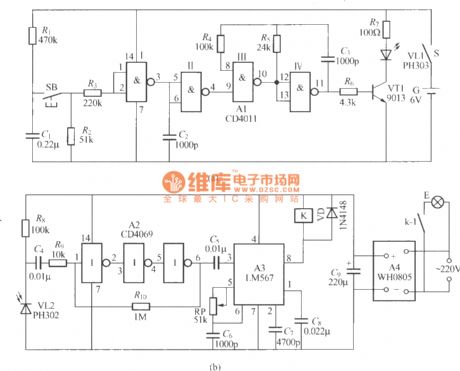
Automatic toilet lamp circuit
Published:2011/7/13 20:36:00 Author:zj | Keyword: Automatic, toilet lamp circuit
As shown in the figure for the automatic toilet lamp circuit, the lamp lights up when people come in and goes out when people go out. At the same time the circuit also has a light control function. The circuit automatically block at daytime, the lamp doesn't light. LED1, LED2 use PH303 type infrared emitting diode. (View)
View full Circuit Diagram | Comments | Reading(936)
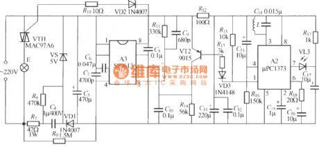
Microwave radar automatic lamp circuit (5)(TX982)
Published:2011/7/4 22:08:00 Author:zj | Keyword: Microwave radar, automatic lamp

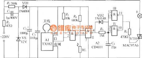
As the diagrams shows it is a automatic lamp with microwave radar TX982. Its feature is that the circuit will not be interfered by its own light and it is vey easy to be installed. It is suitable for washing room,storage room, dresser mirror light etc. It can realize the function that the lamp lights up when people come and it goes out when people leave. (View)
View full Circuit Diagram | Comments | Reading(772)
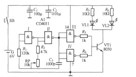
Random electronic dinky toy circuit
Published:2011/5/13 2:59:00 Author:Nicole | Keyword: electronic dinky toy
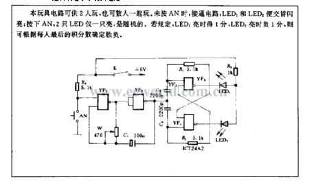
This toy circuit can be played by 2 persons, even more people. If it does not press AN, thecircuit is turned on, LED1 and LED2 is flashing by turns; to press AN, only one of LEDs turns on, it is random. To order if LED1 turns on, it will obtain 1 point, and LED2 turns on, it will obtain negative-one point, the victory or defeat is decided by everyone's final point. (View)
View full Circuit Diagram | Comments | Reading(592)
Half four-bit LCD digital display voltmeter circuit
Published:2011/5/13 2:56:00 Author:Nicole | Keyword: LCD, voltmeter
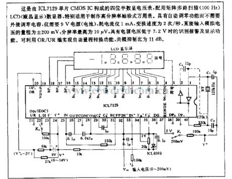
This half four-bit LCD digital display voltmeter is composed of ICL7129 single chip CMOS IC, and with a matrix multichannel scanning(100Hz) LCD digit display device, it is suitable for producing high resolution pocket multimeter. it has the function of automatic zero adjustment and do not need a external connected zero adjustment capacitor, it only needs 9V power supply, the power consumption is 1mA, the transpositional speed is 2/s, the measuring range of direct input analog voltage is ±200mV, the highest resolution is 10μV, it also has the functions of identifying alarm and displaying with lower than 7.2V power voltage. It can use OR/UR terminal to achieve range automatically transforming, the CMRR is 11dB. (View)
View full Circuit Diagram | Comments | Reading(2962)
Ultraweak luminescence measurement circuit
Published:2011/5/13 2:51:00 Author:Nicole | Keyword: ultraweak luminescence
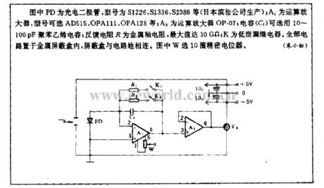
In the figure, PD is photodiode, the model are S1226, S1336, S2386(produced by Janpan Hamamatsu Corporation); A1 is operational amplifier, the model are AD515, OPA111, OPA128; A2 is operational amplifier OP-07; capacitance(C1)can use 10~100pF polystyrene capacitance; feedback resistance R is metal glaze resistance, the maximum can reach 10GΩ; K is low leakage relay. The circuit is in metallic shield box, the shield box is connected to circuit grouding. In the figure, W uses 10 rounds precise potentiometer. (View)
View full Circuit Diagram | Comments | Reading(1093)
| Pages:1499/2234 At 2014811482148314841485148614871488148914901491149214931494149514961497149814991500Under 20 |
Circuit Categories
power supply circuit
Amplifier Circuit
Basic Circuit
LED and Light Circuit
Sensor Circuit
Signal Processing
Electrical Equipment Circuit
Control Circuit
Remote Control Circuit
A/D-D/A Converter Circuit
Audio Circuit
Measuring and Test Circuit
Communication Circuit
Computer-Related Circuit
555 Circuit
Automotive Circuit
Repairing Circuit