
Circuit Diagram
Index 1485
CH217 (alarm device) single chip gas detection alarm circuit
Published:2011/7/20 21:07:00 Author:TaoXi | Keyword: alarm device, single chip, gas detection, alarm circuit
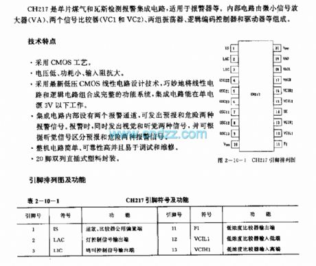
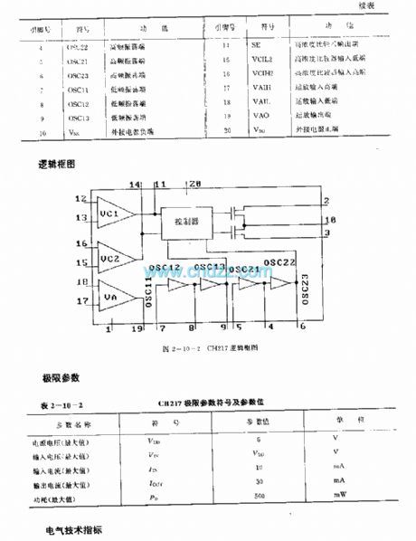
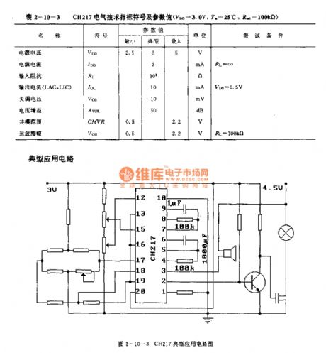
The CH217 is designed as the single chip gas detection alarm circuit that can be used in the alarm device. The internal circuit is composed of the small signal amplifier (VA),two signal comparators (VC1 and VC2), two groups of oscillator, logic code controller and the driver.
Features
The CMOS technology.Low voltage, small power consumption, large input impedance.It uses the new low-voltage CMOS linear circuit design technology, the linear circuit and logic circuit will be combined into the complete function system.The IC can operate in single power 3V condition.The integrated circuit has two internal alarm channels.20-pin dual-row DIP plastic package.
(View)
View full Circuit Diagram | Comments | Reading(773)
CD114CP (sound equipment and FM receiver) FM intermediate frequency amplifier circuit
Published:2011/7/20 21:48:00 Author:TaoXi | Keyword: sound equipment, FM receiver, FM, intermediate frequency, amplifier circuit
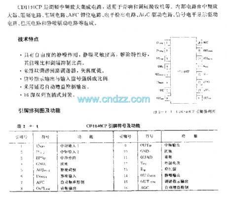
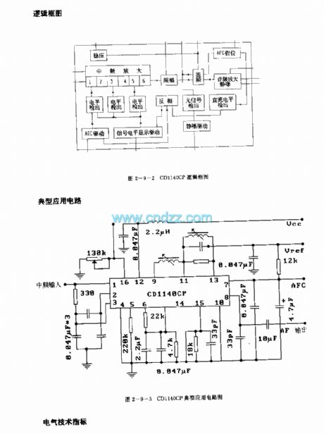
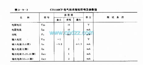
The CD114CP is designed as one kind of FM intermediate frequency amplifier circuit that can be used in the sound equipment and FM receiver. The internal circuit is composed of the intermediate frequency amplifier, the amplitude limiting circuit, the frequency discriminating circuit, the AFC clamping circuit, the level detection circuit, the AGC driving circuit, the signal level display driver circuit, the voltage stabilization circuit and the squelch circuit.
Features
It has the squelch function, the squelch sensitivity is high, the good contact characteristics, the high signal-to-noise ratio and AM rejection ratio.It uses the double-tuned loop tuner, the distortion degree is low.The signal indication output is proportional to the input signal.It uses the delay automatic gain control output.16-pin dual-row DIP package.
(View)
View full Circuit Diagram | Comments | Reading(822)
AN5020 (TV and video recorder) infrared remote control receiving preamplifier circuit
Published:2011/7/20 21:58:00 Author:TaoXi | Keyword: TV, video recorder, infrared, remote control, receiving, preamplifier circuit
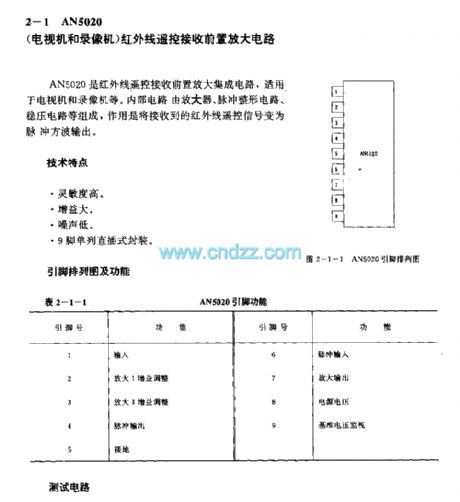
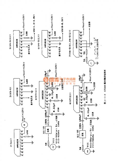
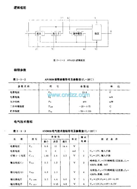
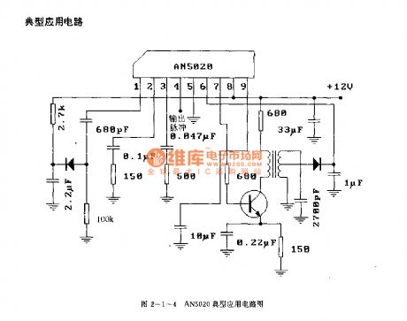
The AN5020 is designed as one kind of infrared remote control receiving preamplifier circuit that can be used in the TV and video recorder. The internal circuit is composed of the amplifier, the pulse shaping circuit, the voltage stabilization amplifier, the function of it is to change the infrared remote control signal into the pulse square wave output.
Features
High sensitivity,Large gain,Low noise,9-pin single row DIP package.
(View)
View full Circuit Diagram | Comments | Reading(2133)
BA2206 (toy car and motorboat) wireless remote control servo system single-chip circuit
Published:2011/7/20 22:22:00 Author:TaoXi | Keyword: toy car, motorboat, wireless, remote control, servo system, single-chip circuit

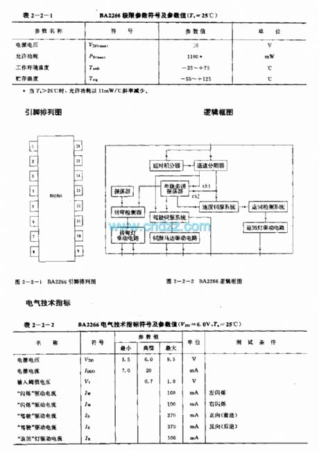
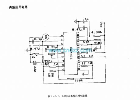
The BA2206 is designed as one kind of wireless remote control servo system single-chip circuit that can be used in the toy car, motorboat or other mobile electronic toys. The internal circuit is composed of the oscillator, the delay integrator, the channel frequency divider, the turning detector, the driving servo system, the speed servo system, the return detection system and a variety of drive circuits. It is in the 18-pin dual-row DIP plastic package.
The motor speed control includes the multi-function control such as the forward drive and back driver.The left and right flashing lights are connected with the output port of the driving servo system, the pulse signal controls the automatic flashing.The flashing light's flashing cycle can be changed by changing the value of external capacitor.
(View)
View full Circuit Diagram | Comments | Reading(3756)
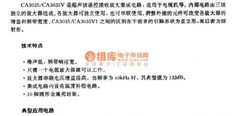
BIJ9149/BIJ9150 general infrared control receiving circuit
Published:2011/7/20 22:53:00 Author:TaoXi | Keyword: general, infrared, control, receiving circuit
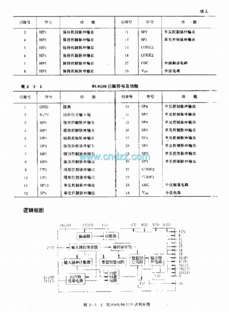
Function description
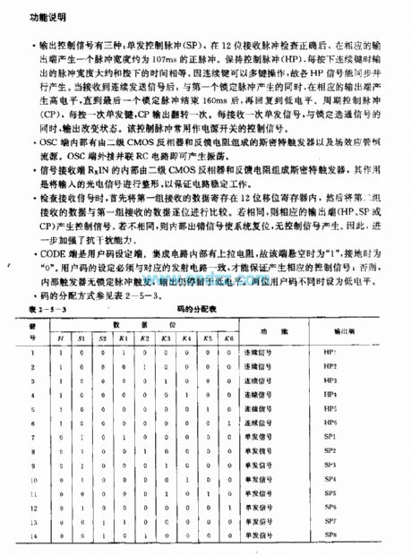
There are three kinds of output control signals: the single control pulse (SP), after the 12-bit receiving pulse is correct, the corresponding output port will produce a positive pulse with the pulse width of 107ms. if you maintain the control pulse (HP), when you press the continuous button, the output pulse width is equal to the press time. The HP signals can be synchronously parallel produced because the continuous key has the multi-key operation function, when it receives the continuous signal, the high level is produced by the corresponding output port.
(View)
View full Circuit Diagram | Comments | Reading(948)
Sequenced flashing AC flash
Published:2011/7/16 3:10:00 Author:leo | Keyword: Sequenced flashing, AC flash

This circuit uses a simple circular counter. The control ports of triac form a part of load. And the three incandescent lamps brighten up in turn and usually one lamp lightens at one time. Impulse frequency can be adjusted which can control the change of lamps. Time period for the change of lamps can be set from 0.1 second to 8 seconds. If the circuit in the dashed box is added, the lamp lightened before will keep light when the next lamp lightens. (View)
View full Circuit Diagram | Comments | Reading(733)
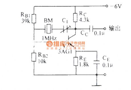
CA3035/CA3035V1 (TV) ultrasonic remote control receiving amplifier circuit
Published:2011/7/21 1:16:00 Author:TaoXi | Keyword: TV, ultrasonic, remote control, receiving, amplifier circuit

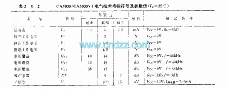
The CA3035/CA3035V1 is designed as one kind of ultrasonic remote control receiving amplifier circuit that can be used in the TVs. The internal circuit is composed of the three-stage independent amplifier. Every amplifier can be used independently, also can be used in tandem. You can change the gain and bandwidth by changing the external components. The difference between the CA3035 and CA3035V1 is that the CA3035's pin shape is upright type, the CA3035V1's pin shape is radiation type.
Features
Low noise, the frequency response is wide.Only one power amplifier.The amplifier series voltage gain is high.When the frequency is 40kHz, the typical value is 132dB.The circuit has the temperature compensation circuit.The 10-pin round metal shell package.
(View)
View full Circuit Diagram | Comments | Reading(1461)
1X0614CE (video tape recorder) infrared remote control receiving preamplifier circuit
Published:2011/7/21 1:24:00 Author:TaoXi | Keyword: video tape recorder, infrared, remote control, receiving, preamplifier circuit
The 1X0614CE has the same features, pin arrangement, pin functions, absolute maximum ratings, electrical specifications, logic diagram and the typical applications with the CX20106, so they can directly exchange. (View)
View full Circuit Diagram | Comments | Reading(477)
Time-scale sawtooth wave generation circuit
Published:2011/7/11 23:32:00 Author:chopper | Keyword: Time-scale, sawtooth wave, generation circuit
View full Circuit Diagram | Comments | Reading(540)
UPCI373H/HA (TV and video tape recorder) infrared remote control receiving preamplifier circuit
Published:2011/7/21 1:58:00 Author:TaoXi | Keyword: TV, video tape recorder, infrared, remote control, receiving, preamplifier circuit
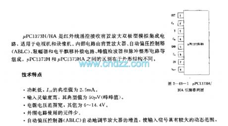

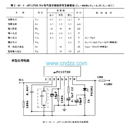
The uPC1373H/HA is designed as the infrared remote control receiving preamplifier bipolar type analog circuit that can be used in the TV and video tape recorder. The internal circuit is composed of the preamplifier, the automatic bias controller (ABLC), the limiter and the level drift compensation circuit, the peak detector, the pulse shaping circuit. The uPC1373H and uPC1373HA have the different shape structure. Features
Low power consumption, the typical value of Icc is 2.5mA.The input sensitivity is high, the typical value is 50uV (peak value).The power voltage range is wide, he value is 6-14.4V.The few external components.The automatic bias controller (ABLC) adjusts the gain of the amplifier automatically, and makes the input signal has the wide dynamic range.
(View)
View full Circuit Diagram | Comments | Reading(1269)
uPDl987C (TV) infrared remote control receiving circuit
Published:2011/7/21 2:18:00 Author:TaoXi | Keyword: TV, infrared, remote control, receiving circuit
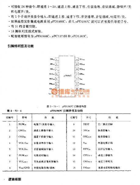
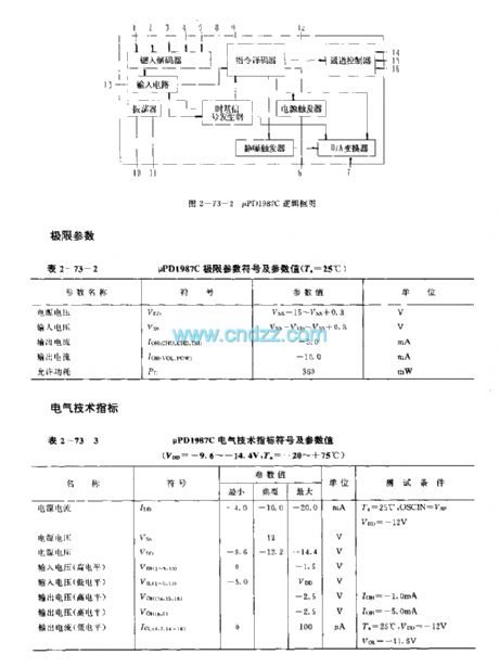
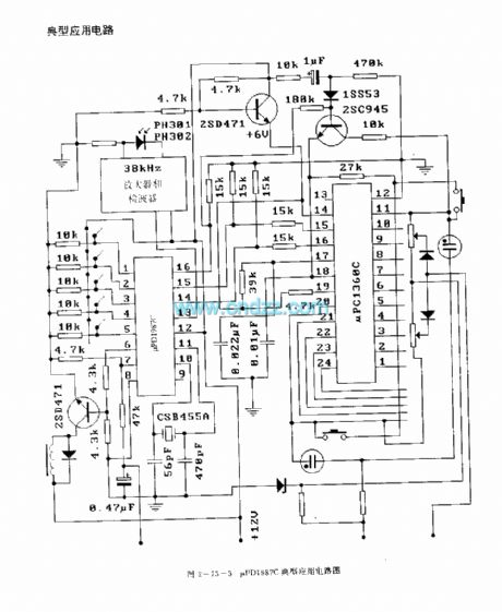
The uPDl987C is designed as the infrared remote control receiving circuit that can be used in the TVs. The internal circuit is composed of the input circuit, the oscillator, the time-base signal generator, the type-in decoder, the instruction decoder, the squelch trigger, the channel controller. The function of it is to decode the signal.
Features
The PMOS technology.It can receive 26 kinds of instructions.It has five manual switches to input the instructions.It has 31 stages of volume control.The 16-pin dual-row DIP package.The matching models are uPD1986C, uPC1373H and the uPD1360C.
(View)
View full Circuit Diagram | Comments | Reading(1074)
Sequenced switching over load circuit
Published:2011/7/16 3:19:00 Author:leo | Keyword: Sequenced switching, load
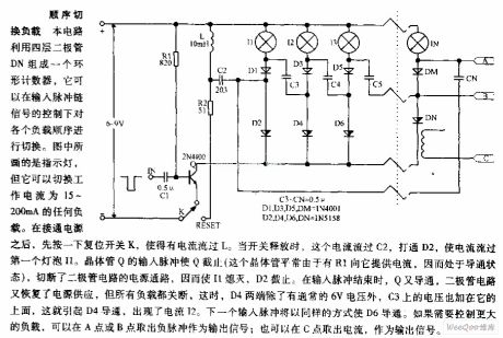
This circuit uses four diodes DN to form a circular counter. It can switch over the sequence of the loads under the control of input impulse signals. As the picture shows, except the indicator lamp, it can switch over any load with the current of 15 mA to 200 mA. When connecting the power resources, please click reset switch K to offer current to Lo. When K is cut off, the current passes through C2. After that, please open up D2, there will be current passing through I1. (View)
View full Circuit Diagram | Comments | Reading(671)
The uPDl937C (TV sets) infrared remote control receiving circuit
Published:2011/7/21 2:20:00 Author:TaoXi | Keyword: TV sets, infrared, remote control, receiving circuit

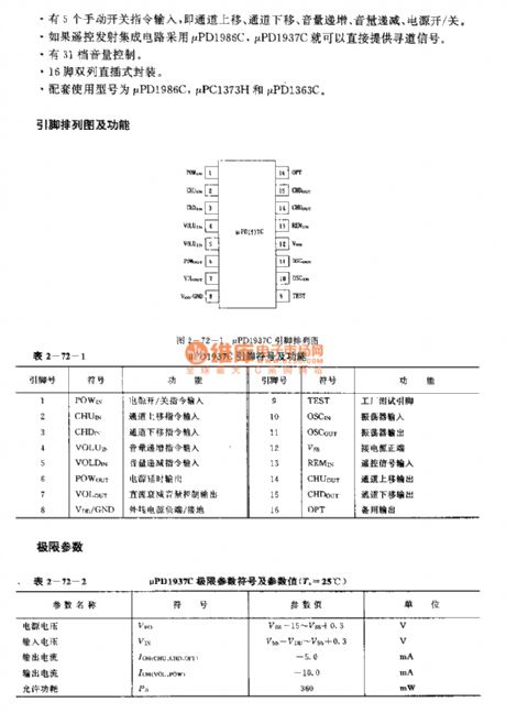
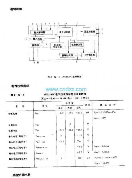
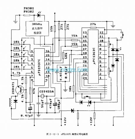
The uPDl987C is designed as the infrared remote control receiving circuit that can be used in the TVs. The internal circuit is composed of the input circuit, the oscillator, the time-base signal generator, the type-in decoder, the instruction decoder, the squelch trigger, the channel controller. The function of it is to decode the signal.
Features
The PMOS technology.It can receive 26 kinds of instructions.It has five manual switches to input the instructions.It has 31 stages of volume control.The 16-pin dual-row DIP package.The matching models are uPD1986C, uPC1373H and the uPD1360C.
(View)
View full Circuit Diagram | Comments | Reading(1309)
UPCI490HA (TV) infrared remote control receiving signal processing circuit
Published:2011/7/21 3:11:00 Author:TaoXi | Keyword: TV, infrared, remote control, receiving, signal, processing circuit
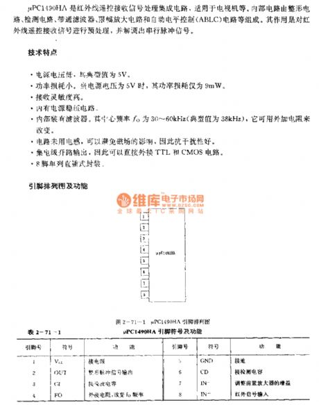
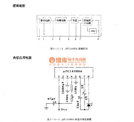
The μPCI490HA is designed as one kind of infrared remote control receiving signal processing circuit that can be used in the TVs. The internal circuit is composed of the shaping circuit, the detection circuit, the bandpass filter, the limiting amplifier and the automatic level control (ABLC) circuit. The function of it is to pretreat the infrared remote control receiving signal and demodulate out the serial pulse signal.
Features
Low power supply voltage, the typical value is 5V.Low power comsumption, when the power supply voltage is 5V, the power comsumption is 9mW.The high receiving sensitivity. It has the power voltage stabilization circuit.It has the filter. The center frequency fo is 30-60kHz (the typical value is 38kHz).The circuit has no electrical inductance to avoid the influence of the magnetic field.8-pin single row DIP package.
(View)
View full Circuit Diagram | Comments | Reading(1059)
μPCI473H/HA (video recorder and TV set) infrared remote control receiving preamplifier circuit
Published:2011/7/21 3:21:00 Author:TaoXi | Keyword: video recorder, TV set, infrared, remote control, receiving, preamplifier circuit
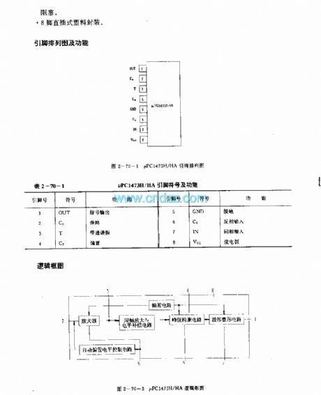
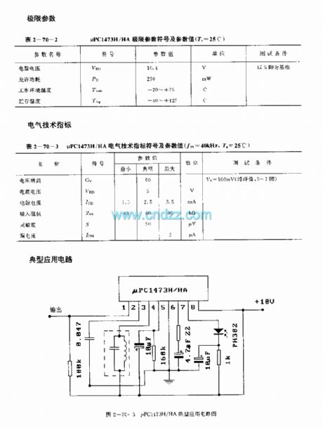
The μPCI473H/HA is designed as one kind of infrared remote control receiving preamplifier bipolar type analog circuit, and it can be used in the video recorder and TV set applications. The internal circuit is composed of the receiving preamplifier circuit, the automatic level control (ABLC) circuit, the amplitude limiting and level compensation, bias, peak value detection and pulse shaping circuit. The μPCI473H and μPCI473HA have the different shape structure.
Features
The high sensitivity, wide dynamic range and strong anti-interference performance.The automatic level control (ABLC) circuit can be used to control the gain of the preamplifier circuit. The 8-pin DIP plastic package.
(View)
View full Circuit Diagram | Comments | Reading(483)
United reaper full warehouse reminder (1)
Published:2011/7/19 23:16:00 Author:chopper | Keyword: United reaper, full warehouse reminder
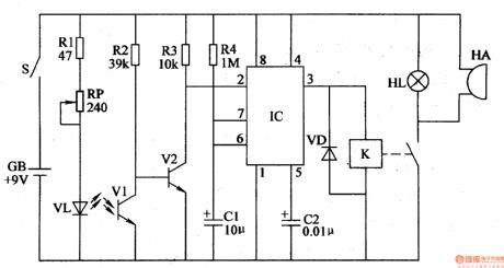
The principle of circuitThe united reaper full warehouse reminder circuit is formed by the photoelectric detection amplification circuit,monostability circuit and the sound and light alarm circuit,which is shown in Figure 4-98. The photoelectric detection amplification circuit is formed by the infrared light-emitting one-diode VL,resistors R1-R3, potentiometer RP, infrared phototransistor V1 and transistor V2. The monostability circuit is formed by the time-base integrated circuit IC,resistor R4 and capacitors C1, C2. The sound and light alarm circuit is formed by the relay K, one-diode VD, indicator light HL and buzzer HA.
(View)
View full Circuit Diagram | Comments | Reading(551)
United reaper full warehouse reminder (2)
Published:2011/7/19 23:16:00 Author:chopper | Keyword: United reaper, full warehouse reminder
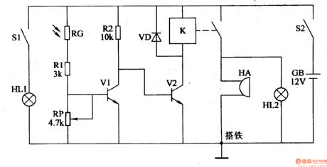
The principle of circuitThis united reaper full warehouse reminder circuit is formed by the photoelectric detection amplification circuit and the sound and light alarm circuit,which is shown in Figure 4-99.The photoelectric detection amplification circuit is formed by the indicator light HL1,light switche S1,photosensitive resistor and transistor V1. The sound and light alarm circuit consists of transistor V2, the relay K, the diode VD, indicator light HL2 and buzzer HA.
(View)
View full Circuit Diagram | Comments | Reading(684)
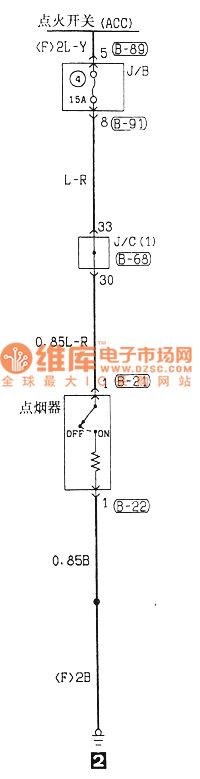
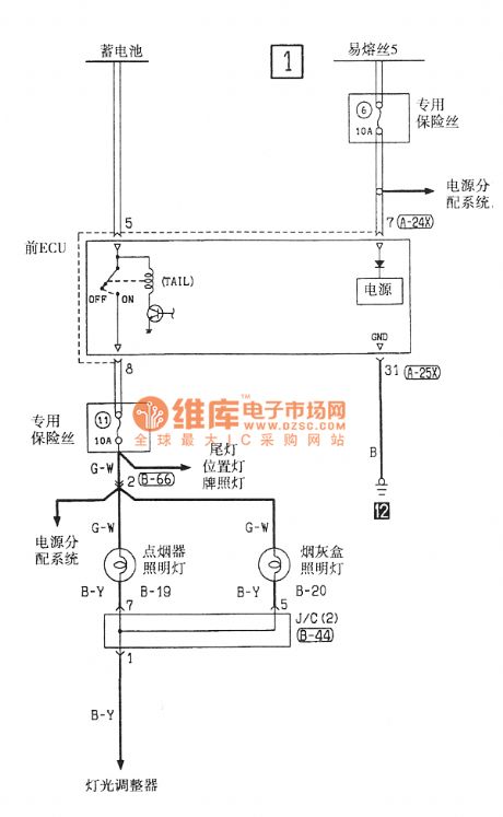
Southeast Ling Sheng cigarette lighter electric system circuit
Published:2011/7/20 23:32:00 Author:leo | Keyword: Cigarette lighter, electric system
View full Circuit Diagram | Comments | Reading(716)
seeder spray pipe water break alarm (1)
Published:2011/7/19 23:44:00 Author:chopper | Keyword: seeder, spray pipe, water break, alarm
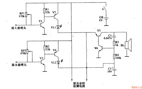
This example describes the seeder spray pipe water break alarm, which can send a sound and light alarm in time to remind workers to process timely when the water breaks. The principle of circuitThe seeder spray pipe water break alarm circuit is formed by water break detection circuit and the sound and light alarm circuit,which is shown in Figure 4-102. Water break detection circuit is formed by the transistors V1,V3,potentiometers RP1,RP2,and resistors R1,R2,etc. Sound and light alarm circuit is formed by the transistors V2,V4-V6,light-emitting diodes VL1,VL2, resistors R3,R4,capacitor C1,C2 and the speaker BL. V2,V4 and VL1,VL2 form the LED indication circuit,and V5,V6 and C1,C2,R3,R4 form the audio oscillator circuit.
(View)
View full Circuit Diagram | Comments | Reading(573)
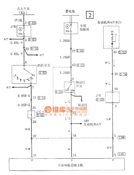
Southeast Ling Sheng navigation electric system circuit
Published:2011/7/20 21:15:00 Author:leo | Keyword: Navigation, electric system
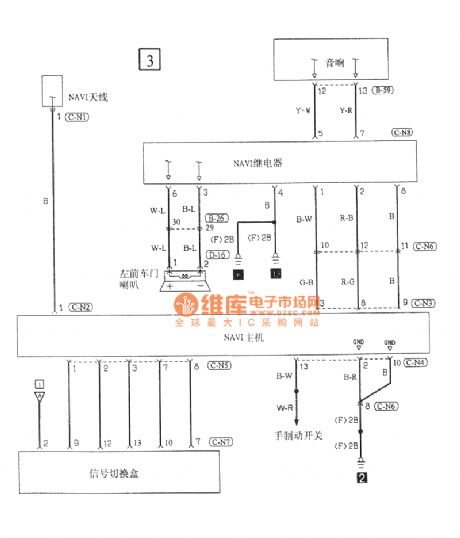
View full Circuit Diagram | Comments | Reading(913)
| Pages:1485/2234 At 2014811482148314841485148614871488148914901491149214931494149514961497149814991500Under 20 |
Circuit Categories
power supply circuit
Amplifier Circuit
Basic Circuit
LED and Light Circuit
Sensor Circuit
Signal Processing
Electrical Equipment Circuit
Control Circuit
Remote Control Circuit
A/D-D/A Converter Circuit
Audio Circuit
Measuring and Test Circuit
Communication Circuit
Computer-Related Circuit
555 Circuit
Automotive Circuit
Repairing Circuit