
Circuit Diagram
Index 1492
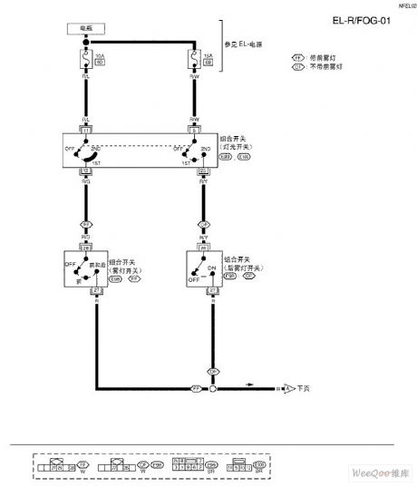
TEANA A33-EL Front Foglight Circuit
Published:2011/7/14 8:39:00 Author:Joyce | Keyword: TEANA , Front Foglight
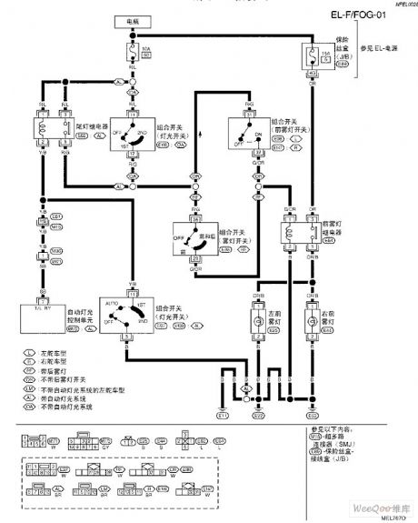
TEANA A33-EL Front Foglight Circuit (View)
View full Circuit Diagram | Comments | Reading(610)
2.4G High-gain Aerial ,WIFI Aerial
Published:2011/7/14 0:20:00 Author:Joyce | Keyword: 2.4G, High-gain, Aerial, WIFI, Aerial

(View)
View full Circuit Diagram | Comments | Reading(988)
Circuit of a Low-pass Filter Composed of Same Parameters with 24 dB Every Octave
Published:2011/7/15 0:58:00 Author:Joyce | Keyword: Low-pass, Filter, Same Parameters, 24 dB, Every Octave
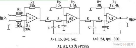
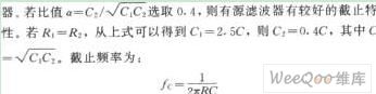
As shown in the figure is the circuit of a low-pass filter composed of same parameters with 24 dB every octave. This circuit is a low-pass filters with 24 dB every octave, which is formed of filtering components of same parameters. In order to get the needed Q value, open-loop op-amp is set to be greater than 1,and at this time the input op-amp becomes 1/2.57 attenuator. The characteristics of the circuit is that when it constitutes multilevel filters, using resistance R of cut-off frequency fc and capacitance C would get the same constant. The parameters of the components in the circuit can be calculated according to the formula fc = 1 / (2 π RC) .The value of resistance ranges from several k Ω to a few hundred k Ω, and the value of capacitance is above several hundred pF.
(View)
View full Circuit Diagram | Comments | Reading(851)
Active Lowpass Filter Circuit with Attenuation of -18dB Every Octave
Published:2011/7/20 3:08:00 Author:Joyce | Keyword: Active , Lowpass, Filter Attenuation , -18dB, Every Octave
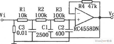
As shown in the figure is an active low pass filter circuit with attenuation of -18dB every octave. The circuit is composed of a passive filter with attenuation of -6 dB every octave and an active filter with attenuation of -12 dB every octave. The whole circuit shows a low pass filter with attenuation of -18 every octave. R1 and C3 form the passive filter, and R2, R3, C1, C2 and operational amplifier constitute the active filter.
(View)
View full Circuit Diagram | Comments | Reading(1157)
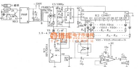
Power Line Carrier Remote Alarm Circuit
Published:2011/7/20 3:09:00 Author:Joyce | Keyword: Power Line , Carrier, Remote Alarm
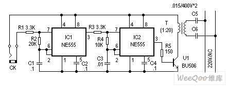
The alarm introduced here does not need circumscribed circuit, but an electric power circuit to send warning signs. Alarm points can be set in many places to conduct sound and light alarm warning for an emergency. It can be used extensively.
Working principle:
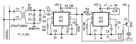
This alarm is composed of sending and receiving signals .The principle of the reflection circuit is as shown in figure 1. It shows two oscillating circuits with different frequency formed by the two 555 time base circuits. When two ends of CK form a short circuit (short circuit alarm probe signal), the first piece (IC1) 555 constitutes a low frequency oscillation circuit, and frequency F1 is mainly decided by C1, R2, and output frequency of feet 3 is the low frequency signal of F1.When feet 3 of IC1 outputs high levels , the second piece IC2 (555) constitutes a high frequency oscillation circuit, and the oscillation frequency is mainly decided by C3, R4.
Components selection and circuit adjustment:
 (View)
View full Circuit Diagram | Comments | Reading(4841)
0-12V Adjustable Voltage Stabilization Circuit
Published:2011/7/17 10:27:00 Author:Michel | Keyword: Voltage Stabilization Circuit
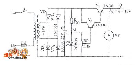
The 0-12 V adjustable voltage stablization circuit is shown as above.Welcome to download the circuit and the information is from www.dzsc.com. (View)
View full Circuit Diagram | Comments | Reading(1139)
TEANA A33-EL Rear Foglight Circuit One
Published:2011/7/14 8:40:00 Author:Joyce | Keyword: TEANA , Rear Foglight
TEANA A33-EL Rear Foglight Circuit (View)
View full Circuit Diagram | Comments | Reading(622)
CXA1262N Monolithic Record and Play Integrated Circuit
Published:2011/7/19 10:42:00 Author:Michel | Keyword: Monolithic, Record and Play, Integrated Circuit
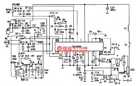
CXA1262N monolithic record and play integrated circuit shown as picture 1 is produced by Sony which is mainly used in pocket recorder.
First CXA1262N Typical Application Circuit.In the circuit,MIC is outside record microphone and VT,T are super audio oscillating circuits. R27 is used to adjust the circuit oscillation frequency. S3 switch is for record/play conversion switch: R23 is to adjust the volume.
Second Signal Flowing Circuit(1) Playback It's in playback situation when S3 is on the position of P.The head loot signal enters the CXAl262N (24) feet and it outputs from (21) feet after preamplifier and frequency compensation. (View)
View full Circuit Diagram | Comments | Reading(549)
TEANA A33-EL Rear Foglight Circuit Two
Published:2011/7/14 8:39:00 Author:Joyce | Keyword: TEANA , Rear Foglight
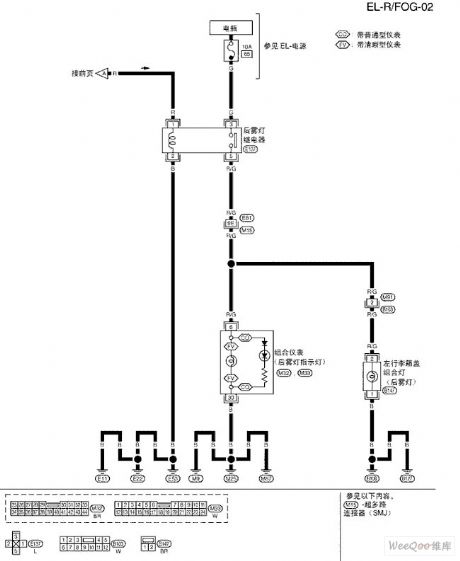
TEANA A33-EL Rear Foglight Circuit (View)
View full Circuit Diagram | Comments | Reading(687)
Visitor or Family Member Differentiated Doorbell Circuit
Published:2011/7/14 0:35:00 Author:Joyce | Keyword: Visitor , Family Member , Differentiated Doorbell
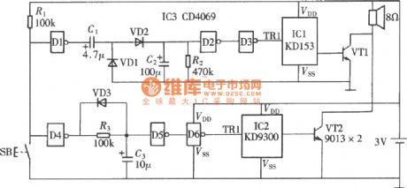
As shown in the figure is a visitor or family member differentiated doorbell(CD4069、KD9300) circuit, which can tell whether it is a visitor or a family member by hearing the times of the doorbell rings. (View)
View full Circuit Diagram | Comments | Reading(869)
Sprinkler Sound Effects Artificial Circuit
Published:2011/7/14 0:36:00 Author:Joyce | Keyword: Sprinkler , Sound Effects , Artificial
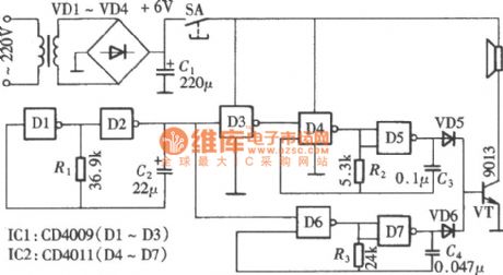
Sprinkler sound effects artificial circuitis composedof a CD4069 and a CD4011, which form three groups of multivibrator with different frequencies. After mixing and modulating, it will produce a sound simulating that of water sprayer. The circuit is as shown in the figure. Two gates of CD4069 in the circuit D1, D2 compose a low frequency multivibrator with R1 and C2, whose function is to control the two audio oscillators to work by turns through cyclical change of the output pulse. (View)
View full Circuit Diagram | Comments | Reading(877)
PDIUSBD12 Chip Feature and 51 Singlechip Interface Circuit
Published:2011/7/13 8:32:00 Author:Michel | Keyword: Chip Feature, 51 Singlechip, Interface Circuit
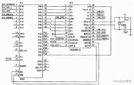
PDIUSBD12 is a performance optimization USB device, usually used in the system based on micro controller. It communicates through the general parallel interface and micro controller and supports local DMA transmission.This device realizes USB interface by using modules and it is allowed to choose the most appropriate micro controller in many micro controllers and it is allowed to use existing micro controller to minimize the devices investment.This flexibility reduces the development time, costs and risks.This device develops an effective way for low cost and high efficiency USB peripherals.
(View)
View full Circuit Diagram | Comments | Reading(1179)
LED Power Level Indicator Circuit of LM324 Design
Published:2011/7/12 3:28:00 Author:Michel | Keyword: LM324 Design, LED , Power Level, Indicator Circuit
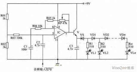
This paper introduces two LED level indicator circuits composed of LM324. The LED level indicator are often applied to audio power amplifier circuit and output power level inductor of power-amplifying circuit. LM324 is four operational Intergrated circuit.
Fitst,the LED PWL inductor introduced firstly has adjustable gain amplification level.It can be connected to audio power amplifier output terminal and also be used as power output level instruction and it could also be connected to the audio preamplifier output terminal (volume control circuit) which is used as prestage indicator.The circuit is showm as above. (View)
View full Circuit Diagram | Comments | Reading(2848)
Highly Reliable Generic Timer Circuit
Published:2011/7/14 8:37:00 Author:Joyce | Keyword: Highly Reliable, Generic , Timer
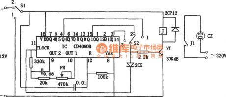
As shown in the figure is a highly reliable generic timing circuit composed of CD4060B. The time of timing the circuit ranges from 1 second to 1 hour, which is controlled by switch S2 control with 3 gears, namely: when S2 is 1, time of timing is 1 ~ 20 seconds ; when S2 is 2, time of timing is 15 ~ 320 seconds; when S2 is 3, time of timing 4 ~ 85 minutes . PR can be used to calibrate the timing time. The timing mode is counting type. CD4060B is a binary 14-level counter. When S1 turns from 1 to 2, the circuit will automatically reset, and timing will start. At that time, J is not actuated, normally closed contact J1 will be on, and voltage on socket CZ will supply power. (View)
View full Circuit Diagram | Comments | Reading(1344)
Preset Outage Timer of Electric Cooker Circuit
Published:2011/7/14 8:38:00 Author:Joyce | Keyword: Preset, Outage , Timer , Electric Cooker
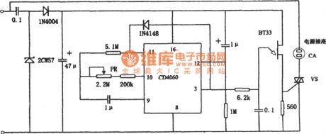
As shown in the figure is a preset outage timer of electric cooker circuit. Time of the timing circuit ranges from 1 hour to 12 hours, which can be regulated by PR .The timing mode is counting typeand control method mode is preset outage timing. The circuit uses BT33 to produce trigger signals of thyristor VS. If BT33 stops vibrating, VS will shut off, and CZ will be interrupted. (View)
View full Circuit Diagram | Comments | Reading(2515)
Generic Subtractor Circuit
Published:2011/7/14 8:36:00 Author:Joyce | Keyword: Generic , Subtractor
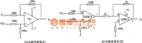
The relation of input and output of the circuit in figure (1) is :V0=Vi2-Vi1. The polarity of the output signal voltage and input voltage of the amplifier are the same. If inverted output is required, the circuit shown in fiure (b ) can be adopted. The relationship of input and output of it is :Vo=Vi1-Vi2 (View)
View full Circuit Diagram | Comments | Reading(716)
Circuit of Multiplying Circuit 1
Published:2011/7/14 0:32:00 Author:Joyce | Keyword: Multiplying
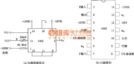
As shown in the figure is a multiplying circuit.
This circuit is composed of 4302, the relationship between input and output is :Vo=Vi1Vi2/10。
The main parameters of 4302:
(View)
View full Circuit Diagram | Comments | Reading(549)
Two-path Video Amplifier Circuit Composed of MAX457
Published:2011/7/14 0:33:00 Author:Joyce | Keyword: Two-path, Video, Amplifier
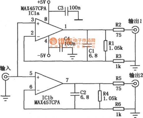
As shown in the figure is the high performance video distributor/amplifier circuit composed of MAX457. MAX457 has two units of video amplifier with stable gains,which could drive 75Ω load directly and its - 3dB bandwidth is not less than 70MHz. Its characteristic is small input capacitance (the typical value is 4pF), 100μA input bias current,high isolation between two amplifiers ( the typical value in 5MHz frequency point is 72dB).
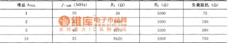
Changing resistance R1, R2,R4, R5, would alter the output impedance of the amplifier circuit as well ,with the specific data shown as follows. (View)
View full Circuit Diagram | Comments | Reading(1146)
Increasing-volume Close-the-door Reminder Circuit
Published:2011/7/14 0:34:00 Author:Joyce | Keyword: Increasing-volume Close-the-door, Reminder
As shown in the figure is an increasing-volume close-the-door reminder circuit. It is used in confidential rooms of banks or other organizations to remind people to shut the door when in and out. When the door remains unclosed for 10s after it is opened, it will give a reminder every two seconds Please close the door with increasing-volume of sound, it will not stop until it is closed. (View)
View full Circuit Diagram | Comments | Reading(887)
Nipper Shape Current Transformer
Published:2011/7/11 22:56:00 Author:Michel | Keyword: Current Transformer

SP is serial nipper shape current transformer is one kind of high accuracy current transformer.It can be used with various testing instruments, such as: multi-function watt-hour meter, recorder, oscilloscope, electric power analyzer, digital multimeter, etc .It can measure all kinds of electric parameter when the tested circuit is not cut off.SP series nipper current transformer specification has complete specifications.Users can select proper nipper current transformer according to different occasions and need.
This transformer is our newest research products.It gets consistent high praise from new and old customers since it enters the market.
Welcome to download and the news is from www.dzsc.com. (View)
View full Circuit Diagram | Comments | Reading(803)
| Pages:1492/2234 At 2014811482148314841485148614871488148914901491149214931494149514961497149814991500Under 20 |
Circuit Categories
power supply circuit
Amplifier Circuit
Basic Circuit
LED and Light Circuit
Sensor Circuit
Signal Processing
Electrical Equipment Circuit
Control Circuit
Remote Control Circuit
A/D-D/A Converter Circuit
Audio Circuit
Measuring and Test Circuit
Communication Circuit
Computer-Related Circuit
555 Circuit
Automotive Circuit
Repairing Circuit