
Circuit Diagram
Index 1478
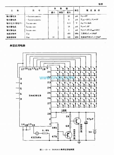
SAA3010 (TV) infrared remote control launch circuit
Published:2011/7/20 7:43:00 Author:Christina | Keyword: infrared, remote control, launch circuit, TV

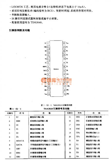
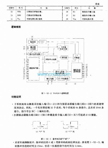
The SAA3010 is designed as one kind of low voltage power supply general general infrared remote control launch circuit. The internal circuit is composed of the oscillator, the test mode circuit, the mode selection circuit, the keyboard encoder, the control unit circuit, the decoder, the keyboard driver decoder, the instruction and system address latch and the frequency divider.
Features
Low voltage power supply, the power consumption is very small,It uses the dual-phase launch technology, the launch time is short,The single pin oscillator input,Every button of the keyboard is the single-pole switch,28-pin dual-row DIP plastic package,The matching model are TDA3048.
(View)
View full Circuit Diagram | Comments | Reading(3216)
Bridging servo circuit with the TA7768F
Published:2011/7/24 20:16:00 Author:Christina | Keyword: Bridging, servo circuit
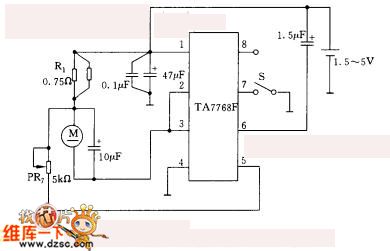
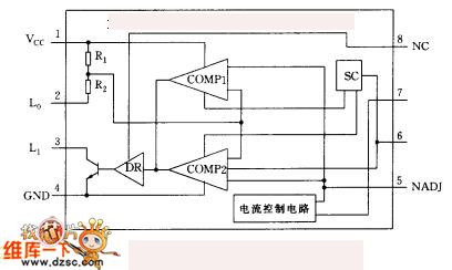
For some low voltage speed control circuits, the selection of the application-specific integrated circuit is very important, it needs to meet the requirements of the circuit such as the internal power consumption, the lowest operating voltage. The bridging servo circuit with the TA7768F is as shown in figure 1, the lowest supply voltage is 1.5V. The internal block diagram of the TA7768F is as shown in figure 2.
The adjustable resistance prt can be used in the fine tuning application of the speed. So we can use it to compensate the dispersion of the electric motor and the integrated circuit parameters.
In addition, you must notice that the small changing of the reference current is related with the dispersibility of the integrated circuit parameters. Also it is related with the variation of voltage, the load change, and the temperature change.
(View)
View full Circuit Diagram | Comments | Reading(636)
Discrete components power driver circuit diagram
Published:2011/7/24 23:33:00 Author:Ecco | Keyword: Discrete components, power driver
View full Circuit Diagram | Comments | Reading(668)
Timing controller circuit diagram
Published:2011/7/24 23:04:00 Author:Ecco | Keyword: Timing controller
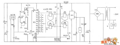
The timing controller circuit is composed of the power supply circuit, clock signal generator, counting distributor circuit, trigger circuit and control output circuit, and the circuit is shown as the chart. Power supply circuit is composed of the power transformer T, bridge rectifier UR, filter capacitors C1, C5, current limiting resistor R5 and Zener diode VS. The clock signal generator is composed of the electronic watch, diode VD1, capacitor C2 and count divider integrated circuit IC1. Counting distributor circuit consists of the counting distributor integrated circuit IC2, resistors R1, R2, timer selector switches S1, S2 and reset button.
(View)
View full Circuit Diagram | Comments | Reading(696)
Fan speed control circuit based on the NE555 time-base circuit
Published:2011/7/24 20:35:00 Author:Christina | Keyword: Fan speed, control circuit, NE555, time-base circuit
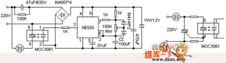
The NE555 of the circuit is connected into the square wave generator with the adjustable duty ratio. When the NE555 outputs the high level, the zero-crossing-on-off-type optocoupler MOC3061's primary stage gets the 10mA forward current to make the internal gallium silicide infrared emitting diode sends out the IR, this IR conducts the photosensitive two-way switch of the zero-crossing detector when the city electricity is crossing zero, and it turns on the power supply of the fan motor, the fan operates to supply the wind. When the pin-3 of the NE555 outputs the low level, the two-way switch turns off, the fan stops.
The MOC3061 has the certain drive ability to directly use the internal two-way switch of the MOC3061 to control the electric fan motor without the power drive component.
(View)
View full Circuit Diagram | Comments | Reading(2754)
555 Bootstrap Pound wave Genenrator Circuit
Published:2011/7/24 1:03:00 Author:Zoey | Keyword: 555 Bootstrap, Pound wave, Genenrator
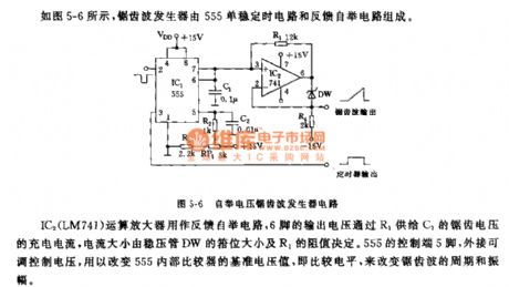
As shown in the figure 5-6, the sawtooth wave generator consists of a 555 single stable circuit and a feedback bootstrap circuit. The IC2 (LM741) operational Amplifier is used as a feedback bootstrap circuit , and the charge current of sawtooth voltage is provided by the output voltage of Pin 6 to C1 through R1, and the current size is determined by the size of the clamp of the voltage regulator tube. The control side of 555 is pin 5, which can adjust and control voltage when attached outside to change the preference voltage of comparator or the comparison level in 555, so that the cycle and amplitude of the sawtooth wave can be changed. (View)
View full Circuit Diagram | Comments | Reading(1189)
The making circuit of the small power synchronous motor governor
Published:2011/7/24 20:44:00 Author:Christina | Keyword: making circuit, small power, synchronous motor governor
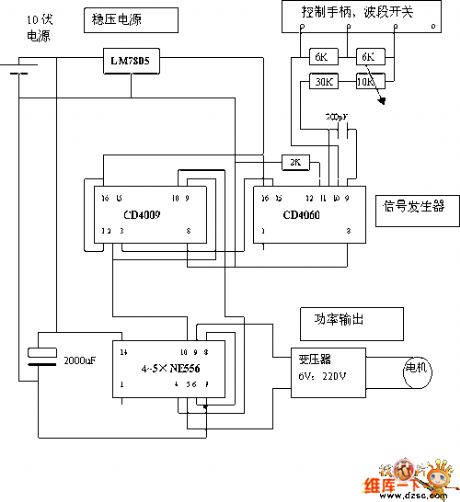
The square wave signal generator is composed of two CMOS circuits cd4060 and cd4069. The cd4060 is the oscillation and frequency division integrated circuit, the oscillation frequency is decided by the product of the capacitance (200pf) and resistance. This high frequency oscillation signal is reduced to about 50Hz through the 10 stages frequency division. The band switch of the control handle can be used to change the resistance value. In the slow stage, the two 6k resistances are connected with the rc oscillator; in the medium speed stage, one of the resistances is in the short circuit state; in the high speed stage, the two 6k resistances are in the short circuit state, the oscillation frequency is the highest.
(View)
View full Circuit Diagram | Comments | Reading(799)
Precision isolated amplifier ISO122/124 pin circuit
Published:2011/7/24 20:55:00 Author:Christina | Keyword: Precision, isolated amplifier, pin circuit
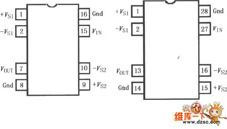
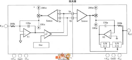
The ISO122/124 is designed as the precision isolated amplifier that has the modulation - demodulation technology of the new operating cycle. When it is sending the signal, the digital signal gets through a 2pF differential capacitance isolation fence, the isolation fence with the digital modulation characteristics will not influence the integrity of the signal, so it has great reliability and high frequency transient suppression. The two gate capacitance are embeded into the same plastic package. The ISO122/124 does not need the external components when it is operating, it has 0.02% nonlinearity, 50kHz signal bandwidth and 200μV/oC Vos drifting. The power supply range is ±4.5~±18V.
(View)
View full Circuit Diagram | Comments | Reading(1390)
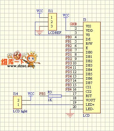
LCD module and controller circuit diagram
Published:2011/7/24 22:41:00 Author:Ecco | Keyword: LCD module , controller
View full Circuit Diagram | Comments | Reading(596)
Simple programmable adjustable timing sequence controller circuit
Published:2011/7/24 21:06:00 Author:Christina | Keyword: Simple, programmable, adjustable, timing sequence, controller circuit
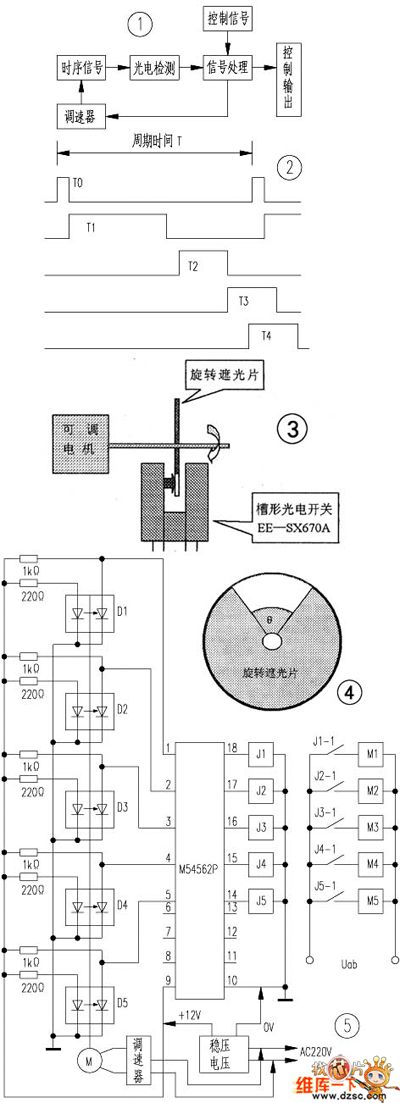
You can use the adjustable motor to drive the round metal (50mm diameter and has the gap design), and this also makes the photoelectric switches which are installed at the both sides of the sheet iron outer perimeter produce the pulse signal (groove shape, the model is: omron ee-sx670a), and this pulse is processed to be the available control signal.
So when we are manufacturing the automatic package machine, we need to use five coaxial rotating shading sheets to control the five actions of t0、t1、t2、t3、t4 respectively.
(View)
View full Circuit Diagram | Comments | Reading(641)
555 E-Lark Circuit changing with Light intensity
Published:2011/7/24 0:43:00 Author:Zoey | Keyword: 555 E-Lark Circuit, changes, Light intensity
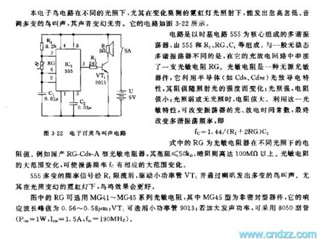
This E-Lark circuit can make a fluctuating and toned sound when exposed in light of different sensitivity, it is like that in the figure 3-22.
The core part of the multi-vibrator is the time-based 555 circuit, which consists of 555, R1, RG and C1.This multi-vibrator concatenates a photoresistance (RG) on its charge and discharge loop, resistance value of this photoresistancewill change as the sensitivity of light changes. This attribute can be used to change the charge and discharge time constant and the frequency of the multi-vibrator, that is, f=1.44/(R1+2RG)C1, GR refers to the photoresistance resistance value in different light sensitivity.
This changeful frequency signal drives the VT1 and makes various bird sounds through the speaker when its current is limited by R2.
We can choose photoresistance series MG41~MG45 used as RG, MG45 is a nonhermetic instrument and its response wave ranges from 0.56 to 0.58μrn, low-power tube 9013 can act as VT1. If you want to strength the vocal power, 8050-type tube can be used. (Pcm=1W,Icm=1.5A, fnt=190MHz)
(View)
View full Circuit Diagram | Comments | Reading(1096)
555 Multi-vibrator with an Adjustable and Independent Charge time
Published:2011/7/24 0:46:00 Author:Zoey | Keyword: 555 Multi-vibrator, an Adjustable and Independent, Charge time
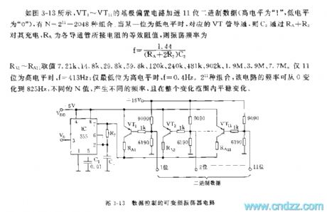
As shown in the picture3-13, base biasing circuit of VT1~VT11 has added 11 binary data, it has 2048 compounding. If any of them becomes low-leveled, the relevant VT pipe will conduct, and C2 charges it through RA+RB, RA refers to the equivalent resistance value of these conduction pipes, its oscillation frequency can be calculated according to the following formula: f=1.44/(RA+2R2)C2
Values of R1~RA1 can be assumed as 7.21k,14.8k,29.8k, 59.8k, 120k, 240k,481k, 902k, 1.9M and 7.7 M. Only when these 11 values are high-leveled, f is equal to 413Hz. If the least significant bit reaches the highest level, f is equal to 0.4Hz. With 2048 mixes, frequency of the circuit ranges from 0~825Hz, different frequencies can be obtained according to different values of N, and the frequencies will change evenly.
(View)
View full Circuit Diagram | Comments | Reading(1109)
12MHz broadband buffer circuit composed of the OPA606
Published:2011/7/24 21:27:00 Author:Christina | Keyword: 12MHz, broadband, buffer
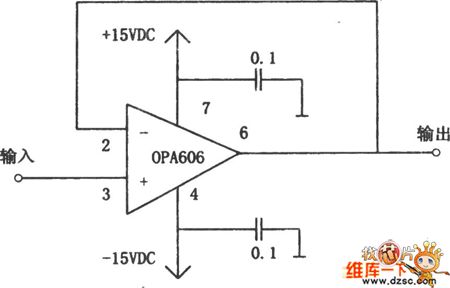
The practical broadband buffer circuit is as shown in the figure. This circuit uses the broadband integrated op-amp OPA606. The OPA606 is the MOSFET input type medium isolation operational amplifier. it has the features of wide frequency band, small bias current, low offset voltage and low distortion degree. In this figure, the input signal adds to the in-phase input port (pin-3) of the OPA606, the output port (pin-6) is connected with the inverting input port (pin-2) by the wire, the circuit forms the voltage follower, the circuit of the figure has the bandwidth of more than 12MHz, the input impedance is 1013Ω.
(View)
View full Circuit Diagram | Comments | Reading(621)
555 Non-TransformerDC/It2 Positive Voltage output circuit
Published:2011/7/24 0:45:00 Author:Zoey | Keyword: Non-TransformerDC, Positive Voltage, output circuit
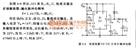
As shown in picture9-6, 555,R1, R2 and C1 constitute an astable multi-vibrator, accordingto the following formula:
f=1.44/(R1+2R2)C1
frequency of output pulse is about 8kHz, and it is output through doubler rectifier D1 and D2. If the input voltage Vin is 14V, then the output voltage ranges from 22V to 26V, the output voltage changes as load change. When load RL is 510Ω, Vo is about 22 V; when it ascends to 51kΩ, Vo is about 24V; and When RL reaches 470kΩ, Vo is about 26V. (View)
View full Circuit Diagram | Comments | Reading(906)
INA326/327 precision Rail-Rail I/O instrumentation amplifier circuit
Published:2011/7/24 21:42:00 Author:Christina | Keyword: precision, Rail-Rail, I/O, instrumentation, amplifier circuit
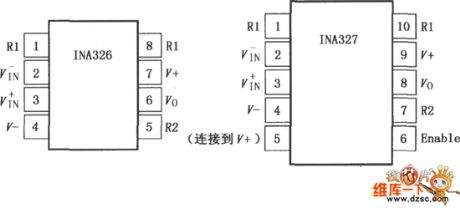
The INA326/327 (with the close function) is the high-performance, low price precision instrumentation amplifier circuit that has the input and output amplitudes of positive and negative power supply voltage (Rail-Rail), it has very low DC error and input common-model range which exceeds the positive and negative Rails, and it can be used in the range of the universal amplification to the high precision amplification. In the using period of products, the super long time stability and the low 1/f noise ensures the low offset voltage and drift. The INA326/327 can be used in the low level sensor amplification, the bridge circuit amplifier, the pressure components, the thermocouple amplification, the wide dynamic range sensor, the high resolution test system, the weight measurement, the multi-channel data acquisition, the medical instrument, the universal amplification.
(View)
View full Circuit Diagram | Comments | Reading(836)
Simple sound control music color light controller circuit
Published:2011/7/24 21:53:00 Author:Christina | Keyword: Simple, sound control, music, color light, controller circuit
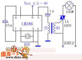
A lots of sound control music color light controller circuits have many audio signal amplifications and three or four transistors, so the circuit is hard to adjust, for some beginners, it is hard to assemble and install. So I use a audio amplification integrated circuit lm386 to assemble and install a music color light controller, the external circuits are very simple. The cost is less than five yuan, and it is very sensitive. The circuit is as shown in the figure, the transformer is the output transformer of the portable radio. The htd is the piezoelectric ceramics with the diameter of 27mm. This circuit can drive a incandescent bulb with the power of lower than 150W.
(View)
View full Circuit Diagram | Comments | Reading(1486)
Chasing type circulation color light control IC Y997A circuit
Published:2011/7/24 22:38:00 Author:Christina | Keyword: Chasing type, circulation, color light, control IC
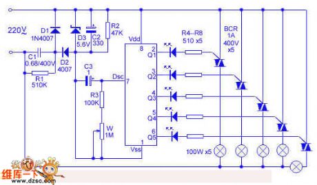
The Y997A is designed as one kind of special flash integrated circuit that uses the standard 8-pin dual-row DIP plastic package. The parameters are as shown: the static current is lower than 5mA, the power supply voltage is 1.8-7V. When the voltage of the output port is 3V, the output current is 15mA, when the voltage is 5V, the output current is 50mA. The breakdown voltage of the output port MOSFET is higher than 18V.
The pin functions of the Y997A are as shown: the VDD power supply of pin-8 is positive. The Vss power supply of pin-1 is negative. The pin-7 dsc is the oscillation input port, you can change the flash frequency by changing the values of the external resistance containers. The pin-2 to pin-6 are q1-q5, they are the flash output port; Y997A is the chasing type circulation color light control IC, the flash sequence is q1→q2→q3→q4→q5→q1→q2....
(View)
View full Circuit Diagram | Comments | Reading(682)
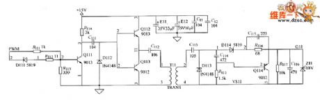
the CATV 60V switch power supply circuit
Published:2011/7/20 0:01:00 Author:Borg | Keyword: switch power supply
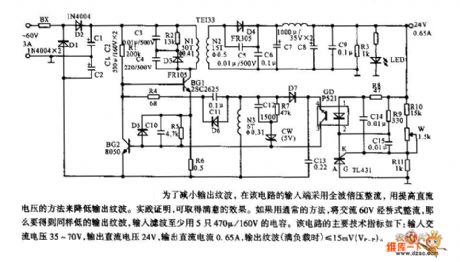
To reduce the wave of the output, the input terminal of the circuit is using full-wave double rectifier, the output wave is reduced by increasing the AC voltage. The practice proves it can get good results. With ordinary methods, the 60V AC is rectified, if we want to get the same low output wave, at least 5 470u/160v capacitors can filter the wave. The parameters are as follows: input AC voltage is 35-70V, output DC voltage is 24V, output DC current is 0.65A, output wave (full load) is ≤15mV(Vp-p). (View)
View full Circuit Diagram | Comments | Reading(2562)
The 3.0L engine oil level sensor circuit of Shanghai GM Buick-MPV (GL8)
Published:2011/7/20 0:01:00 Author:Borg | Keyword: oil level sensor, Buick-MPV
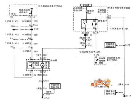
The 3.0L engine oil level sensor circuit of Shanghai GM Buick-MPV (GL8)
(View)
View full Circuit Diagram | Comments | Reading(1837)
The cruise control system of Buick-Regal
Published:2011/7/20 0:01:00 Author:Borg | Keyword: cruise control system, air flow
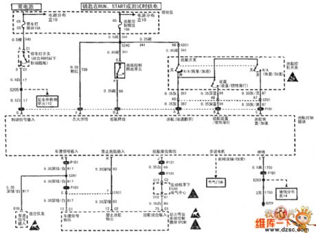
Figure 1: The cruise control system of Shanghai GM Buick-Regal (View)
View full Circuit Diagram | Comments | Reading(593)
| Pages:1478/2234 At 2014611462146314641465146614671468146914701471147214731474147514761477147814791480Under 20 |
Circuit Categories
power supply circuit
Amplifier Circuit
Basic Circuit
LED and Light Circuit
Sensor Circuit
Signal Processing
Electrical Equipment Circuit
Control Circuit
Remote Control Circuit
A/D-D/A Converter Circuit
Audio Circuit
Measuring and Test Circuit
Communication Circuit
Computer-Related Circuit
555 Circuit
Automotive Circuit
Repairing Circuit