
Circuit Diagram
Index 1458
Metal Detector
Published:2011/7/20 5:58:00 Author:Sue | Keyword: Metal, Detector
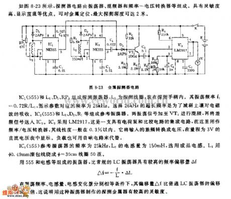
As seen in figure 8-23, the detector circuit consists of oscillator, mixer, frequency to voltage converter. It has many advantages such as high sensitivity, direct display. It can fix the position of metal and the deepest detection depth can reach 2 meters.
IC1(555) and L1,D1,RP1 will compose detecting oscillator. L1 is detecting coil which will be put in the detecting handle. Its oscillate frequency f1=0.72R/L1. The parameter's corresponding frequency in the figure is 26kHz. To choose the extra long frequency of 26kHz can abate the soil's absorption of the electromagnetic wave. IC2(555) and L2,D2,R1 will compose referency oscillator. The two oscillate signals will be put on VT1 to be mixed, and then the difference frequency signal will be put on IC3. IC3 uses LM2917. It is a integrated circuit with charge pump and comparator circuit and is used as frequency to voltage converter. Its degree of linearity is usually within 0.3%. It will convert the input difference frequency into voltage which will be shown in the direct current voltmeter with a range of 3V. The load can also be replaced by audio circuit. (View)
View full Circuit Diagram | Comments | Reading(5039)
555 Illuminations Group Centralized Rectification and Starting Circuit
Published:2011/7/20 5:38:00 Author:Sue | Keyword: Illuminations Group, Centralized Rectification, Starting Circuit
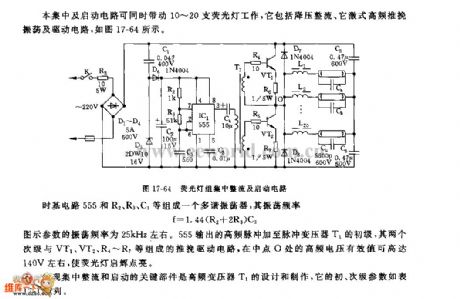
The centralized rectification and starting circuit can drive 10-20 illuminations to work at the same time. As seen in figure 17-64, it consists of voltage reduction, rectification, separate-excited high frequency push-pull oscillation.
Time-base circuit 555 and R2,R3,C3 compose a multivibrator and its oscillate frequency is f=1.44(R2+2R3)C3. The parameter in the figure has an oscillate frequency of about 25kHz. 555's output high frequency pulse will be put on pulse voltage transformer's primary stage. Its two secondary stages and VT1,VT2,R4-R7 will compose push-pull drive circuit. The high frequency voltage's effective valueon the middle point O can reach as high as 140v which will turn on the illuminations.
The criticalthing that can realise centralized rectification and starting are the high frequency voltage transformer T1's design and production. Its primary and secondary parameters will be shown in figure 17-64. (View)
View full Circuit Diagram | Comments | Reading(681)
The automobile multi-function alarm (3)
Published:2011/7/23 3:11:00 Author:qqtang | Keyword: multi-function alarm
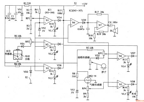
The working principle of the circuitThe automobile multi-function alarm circuit consists of the regulator circuit, storage battery voltage detection circuit, water tank level detection circuit, car door closeing state detection circuit, oil volume detection circuit, alcohol density detection circuit, LED indicator circuit and sound alarm circuit, see as figure 7-99.
The regulator circuit consists of the current limit resistor R1, regulator diode VS1 and filter capacitors of C1 and C2.
(View)
View full Circuit Diagram | Comments | Reading(740)
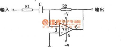
Audio Amplifier Circuit with Adjustable filter
Published:2011/7/18 3:08:00 Author:Sue | Keyword: Audio Amplifier, Adjustable, filter

The audio amplifier uses two integrated circuit. It can tune between the range of 500Hz to 1500Hz, which can be used to drive loudspeaker or earphones. It can be used in clipped wave receiver or other receivers. (View)
View full Circuit Diagram | Comments | Reading(503)
The automobile multi-function alarm
Published:2011/7/23 3:04:00 Author:qqtang | Keyword: multi-function alarm
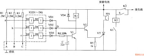
The working principle of the circuitThe automobile multi-function alarm circuit consists of the detection circuit, trigger circuit, voice alarm circuit and control executing circuit, see as figure 7-100.
The detection circuit consists of the control terminal ALC (A is located in the water tank as the water level detection pole; B is located in the general pump liquid as the brake liquid level detecting pole; C is located in the spindle box by the buoy) and resistor R1-R3. The trigger circuit consists of the 6 NAND integrated circuits lC(Dl-D6) and diode VD1-VD3. (View)
View full Circuit Diagram | Comments | Reading(633)
The driller safety protection controller
Published:2011/7/22 23:03:00 Author:qqtang | Keyword: driller, safety protection controller
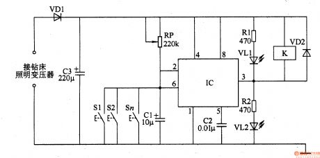
The working principle of the circuit The driller safety protection controller consists of the trigger switches Sl-Sn, resistors of R1 and R2, potentiometer RP, capacitors C1-C3, LED VL1 and VL2, diodes of VD1 and VD2, time-based circuit IC and relay circuit K, see as figure 8-86.
The 6.3V AC voltage from the driller lighting transformer provides with DC working power supply for the IC after it is rectified by VD1 and filtered by C3.
(View)
View full Circuit Diagram | Comments | Reading(646)
Microphone Input Signal Amplifier Circuit
Published:2011/7/14 6:28:00 Author:Sue | Keyword: Microphone, Input Signal, Amplifier
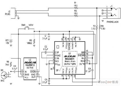
The earphone amplifier(U1,MAX4411) and the microphone amplifier(U2,MAX9812) can use 3v battery as supply power directly. When it is in standard mode, these two appliances are both disconnected, which will consume extra-low battery current. When there is need to talk with others, only the transient switch SW1 should be pushed to start the microphone. Then the microphone's amplifier's bias output will be opened which can amplify the outside audio signal. Then connect the amplified signal to the earphone amplifier and put it into earphone's audio signal through resistor R3,R4. Another advantage of such mix method is that the earphone amplifier's low-impedance(when started) can decay the earphone access's audio current. (View)
View full Circuit Diagram | Comments | Reading(693)
The punch safety protection controller
Published:2011/7/22 22:54:00 Author:qqtang | Keyword: protection controller
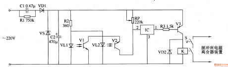
Here is to introduce a punch safety protection controller which can automatically cut off the power supply circuit of the punch electric magnetic clutch when the hand is close to the modes, so the punch won't injure the operator's hand, thus the safety of the operator is assured.The working principle of the circuitThe punch safety protection controller circuit consists of the DC regulator power supply circuit, infrared detection control circuit and control executing circuit, see as figure 8-87.
(View)
View full Circuit Diagram | Comments | Reading(649)
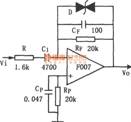
Controllable Integrator(F007) Circuit
Published:2011/7/22 6:38:00 Author:Sue | Keyword: Controllable Integrator
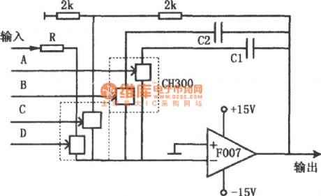
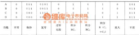
Figure1 Controllable integrator (F007) circuit
Table1 Controllable integrator's function table.
The picture shows the controllable integrator circuit. The circuit has controllable integrator with a complex zero, maintain and different integration time constants. The analog switch is CH300, operational amplifier is F007. In the picture, the values of R,C1,C2 can be configure according to actual requirement. The different control states of the four analog switches can drive the circuit to complete different functions. The diagram shows the relations between the states and functions of control terminal A,B,C,D. (View)
View full Circuit Diagram | Comments | Reading(693)
Low Cost Differentiator Circuit Composed of CC4069
Published:2011/7/22 7:06:00 Author:Sue | Keyword: Low Cost, Differentiator
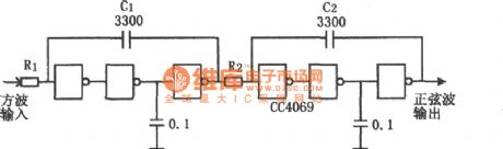
The picture shows the low cost differentiator circuit. Usually differentiator consists of operational amplifier, but CMOS phase inverter CC4069 can also compose differentiator with good effect and low cost. Because of CMOS GATE's advantage of linear amplification, it is used to compose differentiator. In the circuit, R1 and R2 can be changed to meet the demand of frequency of amplitude. The two capacitors of 0.1μF are used as compensation to avoidunnecessary oscillation. The integrated circuit can also use GATE circuit of other phase inverter forms, but there should be no buffer, that is a single-stage gate. (View)
View full Circuit Diagram | Comments | Reading(590)
The industrial oil furnace controller (1)
Published:2011/7/23 2:37:00 Author:qqtang | Keyword: oil furnace, controller
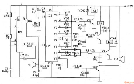
The working principle of the circuitThe industrial oil furnace controller consists of the multi-resonance oscillator, control circuit and fire detection/extinguish alarm circuit, see as figure 8-88.
The multi-resonance oscillator consists of the time-based circuit IC1, resistors of R1 and R2, capacitor C1. The control circuit consists of the counter/pulse distributor circuit IC2, reset key S, diode VD1-VD4, resistor R3-R8, transistor V2-V4, relay K1-K3, capacitors C3 and C5-C7. (View)
View full Circuit Diagram | Comments | Reading(812)
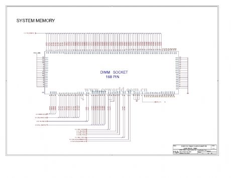
Computer motherboard circuit 810 2_13
Published:2011/7/27 1:13:00 Author:Ecco | Keyword: Computer motherboard

View full Circuit Diagram | Comments | Reading(567)
Computer motherboard circuit 810 2_12
Published:2011/7/27 1:13:00 Author:Ecco | Keyword: Computer motherboard
View full Circuit Diagram | Comments | Reading(544)
Computer motherboard circuit 810 2_11
Published:2011/7/27 1:12:00 Author:Ecco | Keyword: Computer motherboard
View full Circuit Diagram | Comments | Reading(584)
Basic Differentiator Circuit
Published:2011/7/21 0:58:00 Author:Sue | Keyword: Basic, Differentiator

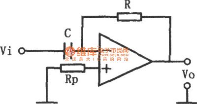
The picture shows the basic differentiator circuit. The circuit can realise differential operation of input and output. The relation between input and output is v0=-RC dv1/dt. (View)
View full Circuit Diagram | Comments | Reading(734)
Four Interlock Switch Controller(CD4028) Circuit
Published:2011/7/23 5:38:00 Author:Sue | Keyword: Four Interlock Switch Controller(CD4028) Circuit

The four interlock switch controller circuit shown in the picture uses one decimal docoder integrated circuit CD4028 with four BCD code input terminals which have 10 decoding output terminals. The circuit uses its four special input codes to compose a four interlock switch controller. Its circuit is shown in the picture. The circuit consists of CD4028 and four button input switches SB1-SB4 and four output indicator circuit.Four output terminals will be connected to control circuit. CD4028 is 16-pin flat plastic structure, and its four input terminals are A,B,C,D. Its ten output terminals are Q0-Q9. (View)
View full Circuit Diagram | Comments | Reading(6695)
Improved Differentiating Circuit
Published:2011/7/21 0:53:00 Author:Sue | Keyword: Improved, Differentiating
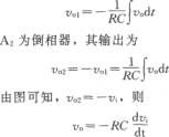
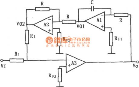
The picture shows the improved differentiating circuit. In the picture, A1 is integrator, and its output is V01=-1/RC ∫v0dt.
A2 is phase inverter, and its output is v02=-v01=1/RC ∫v0dt.
From the picture we know that, v02=-v1, so v0=-RC dv1/dt. (View)
View full Circuit Diagram | Comments | Reading(615)
Low Noise Differentiator Circuit
Published:2011/7/22 6:52:00 Author:Sue | Keyword: Low Noise, Differentiator
The picture shows the low noise differentiator circuit. The circuit is made by adding some components to the basic differentiator so it has overload protection capability with good stability and low noise. R's access can make the circuit stable and can reduce the noise, increase the input impedance. When working frequency of the differentiator is not high, in order to restain high frequency noise, capacitor Cp is added. Voltage-regulator tube is set on consideration that there may be large single-stage noise. Cp can help to maintain the stability of the circuit. (View)
View full Circuit Diagram | Comments | Reading(918)
The car sound burglarproof alarm (1)
Published:2011/7/23 2:51:00 Author:qqtang | Keyword: burglarproof alarm
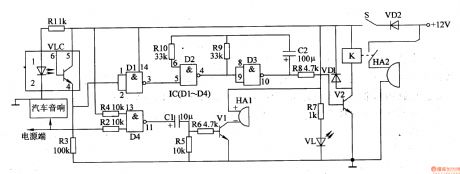
The working principle of the circuit The car sound burglarproof alarm consists of the photoelectric detection control circuit, self-detection circuit, low-frequency oscillator circuit and alarm circuit, see as figure 7-10.
The photoelectric detection control circuit consists of the photocoupler VLC, resistors of R1 and R3, the D1 inside the 4 NAND integrated circuits IC(Dl-D4). The self-detection circuit consists of the resistors of R2 and R4-R7, D4 inside IC, capacitor C1, transistor V1, LED VL and buzzer HA1. (View)
View full Circuit Diagram | Comments | Reading(743)
Practical Differentiator Circuit
Published:2011/7/21 8:58:00 Author:Sue | Keyword: Practical Differentiator
The picture shows the practical differentiator circuit. The circuit consists of common operational amplifier. When the differentiator inputs a triangle wave, it outputs a square wave. The frequency of the input signal is decided by the resistor R1,R2 and the capacitor C. The circuit requires R1's resistance value to be 1/10 of R2's resistance value, that is:
R1=R2/10.
The capacitor C's capacitance value is determined by R2's value as well as the input frequency fin, and their relation is:
C=1/R2fin.
Similarly, if C's value is already known, then R's value can be got from the following formula:
R2=1/Cfin. (View)
View full Circuit Diagram | Comments | Reading(1257)
| Pages:1458/2234 At 2014411442144314441445144614471448144914501451145214531454145514561457145814591460Under 20 |
Circuit Categories
power supply circuit
Amplifier Circuit
Basic Circuit
LED and Light Circuit
Sensor Circuit
Signal Processing
Electrical Equipment Circuit
Control Circuit
Remote Control Circuit
A/D-D/A Converter Circuit
Audio Circuit
Measuring and Test Circuit
Communication Circuit
Computer-Related Circuit
555 Circuit
Automotive Circuit
Repairing Circuit