
Circuit Diagram
Index 1444
REMOTE_FIELD_STRENGTH_METER
Published:2009/6/16 2:10:00 Author:May
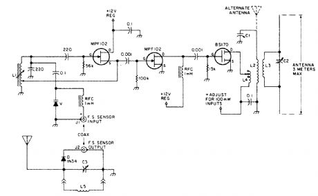
This field strength meter consists of a tuned crystal detector producing a dc output voltage from a transmitted signal. The dc voltage is used to shift the frequency of a transmitter of 100-mW power operating at 1650 kHz. The frequency shift is proportional to the received field strength. This unit has a range of several hundred feet and is operated under FCC part 15 rules (100-mW max power into a 2-m-long antenna between 510 and 1705 kHz). (View)
View full Circuit Diagram | Comments | Reading(784)
MANUAL_HEADLIGHT_SPOTLIGHT_CONTROL_FOR_AUTOS
Published:2009/6/16 2:07:00 Author:May
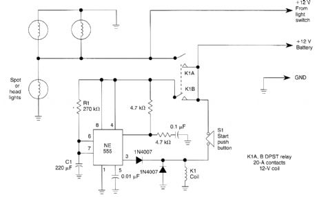
Pressing the START pushbutton turns on either the headlights or spotlights for a predtermined time. After 1 minute (R1 and C1 determine this), the lights will shut off as the NE555 completes its cycle. (View)
View full Circuit Diagram | Comments | Reading(712)
FAX_MATE
Published:2009/6/16 2:03:00 Author:May

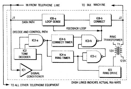
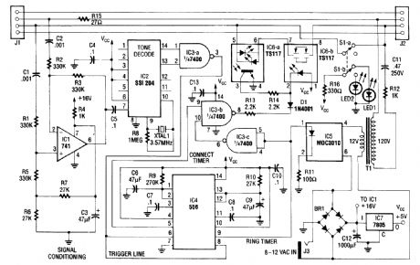
The fax mate separates the fax machine from the phone line, rings the fax machine on com-mand, connects equipment to incoming lines, and senses the end of the message. When a touch tone pound signal (#) is detected, it actuates a ring greater and driver for the fax machine (the # signal is not used in ordinary dialing). The connect signal is inhibited for this time (ring cycle).1C46 runs for 15 s and drives part of the connect IC. Then the fax or modem has fired up and is sending out a handshake tone. IC6 connects the equipment for initial hookup and keeps the connect section powered. When the fax machine hangs up, the loop current detector turns off, and resets the system. (View)
View full Circuit Diagram | Comments | Reading(2259)
ELECTRONIC_DOOR_BUZZER
Published:2009/6/16 2:00:00 Author:May
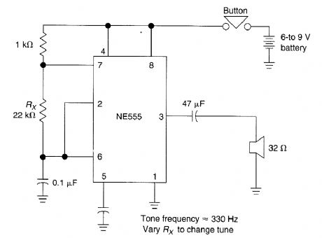
This simple electronic door buzzer draws no quiescent current. When S1 is pressed the speaker produces a tone. The NE555 (U1) generates signal. (View)
View full Circuit Diagram | Comments | Reading(3)
TWIN_BELL_CIRCUIT
Published:2009/6/16 1:59:00 Author:May
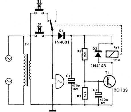
It is often desirable for a single doorbell to be operated by two buttons, for instance, one at the front door and the other at the back door.The additional button, S2 in series with the break contact of relay Re 1, is connected in parallel with Lhe original bell-push, S1. When S2 is pressed, the bell voltage is rectified by D1 and smoothed by Cl. After a time, t= R1R2C2, the direct voltage across C2 has risen to a level here T1 switches on. Relay Rel is then energized and its contact breaks the circuit of S2 so that the bell stops ringing. After a short time, C1 and C2 are discharged, the relay retums to its quiescent state and the bell rings again.In this way, S1 will cause the bell to ring continuously, while S2 makes it ring in short bursts, so that it is immediately clear which button is pushed. (View)
View full Circuit Diagram | Comments | Reading(904)
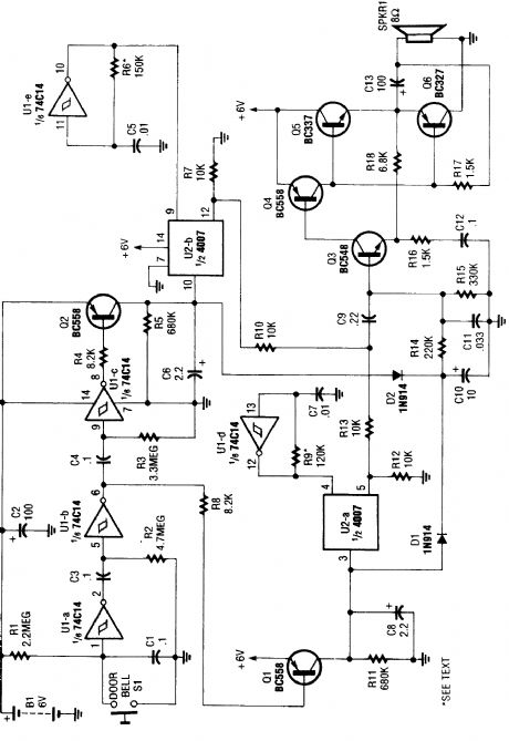
SMART_TURN_SIGNAL
Published:2009/6/16 1:59:00 Author:May
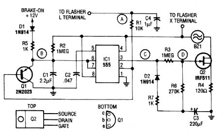
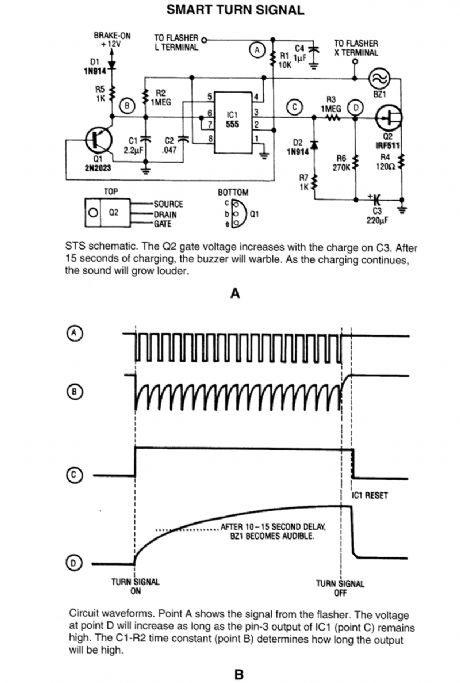

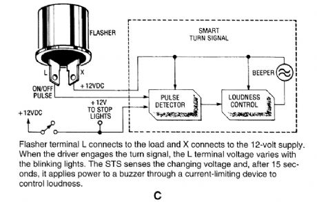
This circuit reminds a driver that his tun signal has been left on for more than 15 seconds. When stopped for a light, the brake-on signal holds the warning off. (View)
View full Circuit Diagram | Comments | Reading(862)
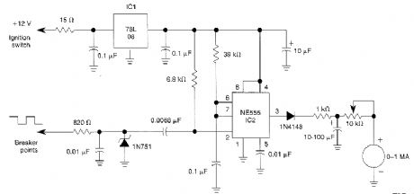
ELECTRONIC_DOORBEL
Published:2009/6/16 1:56:00 Author:May
When the doorbell switch is pressed,the two monostable stages are activated in sequence,appling bias to a pair of voltagecontrolled resistor stages.These then modulate the outputs fro, a pair of tone generators.The resulting signals are fed to an audio amplifier,then to the speaker. (View)
View full Circuit Diagram | Comments | Reading(817)
VEHICULAR_TACHOMETER_CIRCUIT
Published:2009/6/16 1:49:00 Author:May
In this automotive application, the 555 is a pulse counter. IC1 regulator provides proper operating voltage for IC2. This circuit is for vehicles with conventional breaker points. (View)
View full Circuit Diagram | Comments | Reading(815)
BRAKE_AND_TURN_SIGNAL_LIGHT_CIRCUIT
Published:2009/6/16 1:48:00 Author:May

This circuit enables single-filament tail lights to serve as combination brake lights and turn signals. (View)
View full Circuit Diagram | Comments | Reading(914)
CD_IGNITION_SYSTEM_FOR_AUTOS
Published:2009/6/16 Author:May
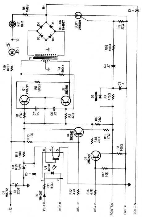
At the heart of the CD4-MX is an astable multivibrator, built around Q1 and Q2, that feeds step-up transformer T1. The out-put of T1 is rectified by D3 to D6 and used to charge capacitor C4. When the points colse, a small voltage is fed to the gate of SCR1, causing it to fire, dumping the charge of C4 to the vehicle's ignition coil. The circuit also contains optional subciruits to accommodate different types of auto ignitions.X15 + and X15 - are alternative trigger configurations for nonponit breaker ignition systems. R6 is not used for these systems and must be removed. Optocoupler U1 can be used (pin 4) in conjunction with X15 - or X15 + depending on polarity of sensor. Note that 60 to 70 kV is available from this system, so observe suitable safety precautions. (View)
View full Circuit Diagram | Comments | Reading(991)
4543B_COMMON_CATHODE_LED_DRIVER
Published:2009/6/15 23:50:00 Author:May
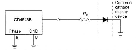
This circuit shows a way of driving a com-or an LED with a common cathode display segment CD4543B. (View)
View full Circuit Diagram | Comments | Reading(753)
FLUORESCENT_TUBE_DISPLAY_DRIVER
Published:2009/6/15 23:50:00 Author:May
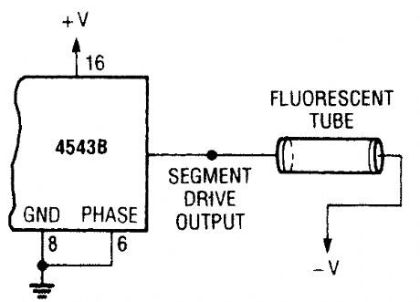
A fluorescent tube or display can be driven with a 4543B IC, as shown. (View)
View full Circuit Diagram | Comments | Reading(844)
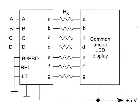
4511B_COMMON_ANODE_DISPLAY_DRIVER
Published:2009/6/15 23:49:00 Author:May
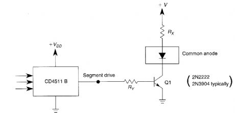
The use of a switching transistor (like a 2N2222 or 2N3904) allows use of the CD4511B with a common-anode display. Ry should be chosen to provide about 1 mA to drive Q1 and Rx should provide enough current to drive the display. For this circuit, the transistor gain (HFE) should be at least the ratio of the segment drive current to the current through Rx (View)
View full Circuit Diagram | Comments | Reading(1134)
GAS_DISCHARGE_TUBE_OR_DISPLAY_DRIVER
Published:2009/6/15 23:47:00 Author:May
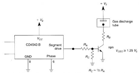
To drive the display, RA should provide a drive of about 1 mA to the gas discharge tube. RB is a current-limiting resistor. (View)
View full Circuit Diagram | Comments | Reading(763)
4543B_7_SEGMENT_LCD_DRIVER
Published:2009/6/15 23:42:00 Author:May
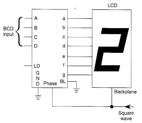
The circuit shows a frequently-used method of driving an LCD display. A square-wave drive is necessary for this application. (View)
View full Circuit Diagram | Comments | Reading(1635)
7_SEGMENTLEDDISPLAY_DRIVER
Published:2009/6/15 23:41:00 Author:May
AIL IC1 like a 7447 drives a 7-segment commoll anode LED display.Current limiting reslstor R should limit the segment current to the rated value at maxlmum supply voltage A sample calculation is shown (View)
View full Circuit Diagram | Comments | Reading(3443)
7_SEGMENT_COMMON_CATHODE_LED_DISPLAY_DRIVER
Published:2009/6/15 23:40:00 Author:May
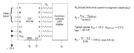
A CD4511B CMOS LED display driver can be used to drive a common cathode LED display. Cur-rent limiting resistors limit the segment current to the rated value at maximum supply voltage. A sample calculation is shown. (View)
View full Circuit Diagram | Comments | Reading(1490)
ALCAUTOMATIC_LEVEL_CONTROL
Published:2009/6/15 23:33:00 Author:May
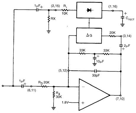
The rectifier input is tied to the input. This makes gain inversely proportional to input level so that a 20-dB drop in input level will produce a 20-dB increase in gain. The output will remain fixed at a constant level. The circuit will main-tain an output level of ±1 dB for an input range of +14 to -43 dB at 1 kHz. Additional extemal components will allow the output level to be ad-justed. (View)
View full Circuit Diagram | Comments | Reading(597)
LED_DISPLAY_LEADING_ZERO_SUPPRESSOR
Published:2009/6/15 23:33:00 Author:May
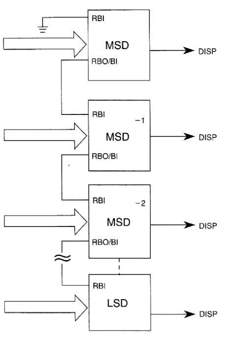
The diagram shows how to connect 7447-type IC devices for leading-zero suppression in an LED display. (View)
View full Circuit Diagram | Comments | Reading(764)
7_SEGMENT_LCD_DRIVER
Published:2009/6/15 23:32:00 Author:May
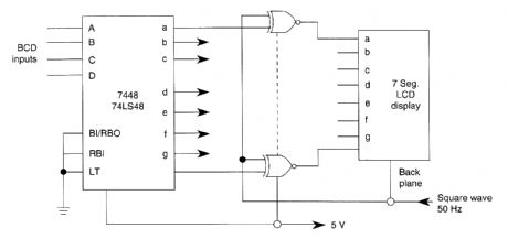
This circuit shows how a 7448 IC is used to drive a 7-segment LCD display. Atn external 50-Hz square wave supplies necessary phase signals to the back plane of the display. (View)
View full Circuit Diagram | Comments | Reading(3730)
| Pages:1444/2234 At 2014411442144314441445144614471448144914501451145214531454145514561457145814591460Under 20 |
Circuit Categories
power supply circuit
Amplifier Circuit
Basic Circuit
LED and Light Circuit
Sensor Circuit
Signal Processing
Electrical Equipment Circuit
Control Circuit
Remote Control Circuit
A/D-D/A Converter Circuit
Audio Circuit
Measuring and Test Circuit
Communication Circuit
Computer-Related Circuit
555 Circuit
Automotive Circuit
Repairing Circuit