
Circuit Diagram
Index 1441
ACTIVE_FOURTH_ORDER_HIGH_PASS_FILTER_FOR_50_Hz
Published:2009/6/16 21:08:00 Author:May
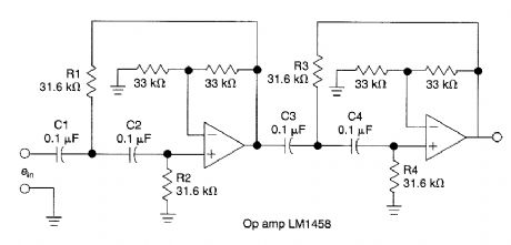
This circuit which uses an LM1458 or similar op amp is a fourth-order high-pass filter with a 24 dB/octave roll-off The values of R1/R2,R3/R4,C1/C2,C3/C4 can be scaled to suit other cutofffre quencies (View)
View full Circuit Diagram | Comments | Reading(1702)
CAR_BATTERY_TESTER_FOR_CRANKING_AMPS
Published:2009/6/16 4:39:00 Author:May
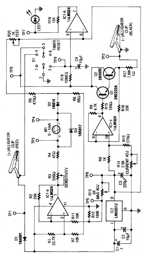
This circuit determines the cold cranking amps of a battery by firest discharging the surface charge, then checking the internal resistance. This gives a more realistic measurement than simply measuring the instantaneous drop in voltage with a load. A constant-current source draws 2.5A. Then, after one minute, a voltage drop measurement is made under load. (View)
View full Circuit Diagram | Comments | Reading(1052)
BATTERY_TESTER_
Published:2009/6/16 4:04:00 Author:May
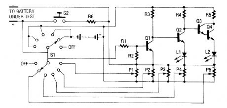
The battery tester uses four transistors and two LEDs to indicate the condition of any battery you want to test. Q3 and Q4 are connected in a Darlington configuration that has extremely high gain. LED L2 lights when a small positive potential appears on the base of Q3. Transistors Q1 and Q2 form a direct-coupled dc-amplifier circuit. The output of this stage drives the red LED L1. Rotary switch 51 is used to select different ranges (which have been previously set by adjusting trimmer resistors PI through P5).The positive (+) lead goes through the selected contacts of S1 to the biasing resistors R3, R4, and R5. The negative (-) lead of the battery under test goes to the ground or common lead of the circuit and the (+) side to one side of P1 through P5.L1 Red LEDL2 Green LEDP1 through P5 5-kΩ trimmer resistorR1 100 kΩR2, R3 33 kΩR4, R5 470 ΩR6 12 Ω 1WS1 2 P6 position NS rotary switchS2, NO pushbutton switchDepending on the position of S1, a particular trimmer resistor (wiper lead) is selected. That lead goes through the contact on S1 to resistor R1 and into the base of npn transistor Q1. If the battery is good enough, (+) voltage goes to the base of Q1, turning it on. This turns Q2 off, which then allows Q3 to turn on. That causes Q4 to turn on and light green LED L2.If the battery is weak, Q1 will not turn on, which will cause Q2 to be biased on by R3, which in turn lights red LED L1. When Q1 is on, it biases the base of Q3 negative, and causes Q3 to be turned off. That prevents L2 from turning on.The circuit operates in the same manner for all ranges except the first two, where a 9-V battery has been added by S1 to be in series with the input voltage to allow for testing of very low voltage batteries. That is because at voltages below 2 Vdc, LEDs will not light and the circuit would be unable to set a low-voltage (<2-V) battery without the additional internal-battery voltage. A load resis-tor has also been included; it allows the battery under test to be connected to a load to give a better indication of its condition. That load resistor is connected across the battery when normally open (NO) switch S2 is depressed. (View)
View full Circuit Diagram | Comments | Reading(955)
INTELLIGENT_BATTERY_CHARGING_CIRCUIT
Published:2009/6/16 3:35:00 Author:May
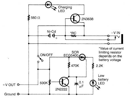
Intended for a Nicad application this charging circuit can be used with a wide range of batteries. A low-battery detector is intended. The trip voltage is set via the 500-kΩ pot. Select R, for the battery you intend to use. (View)
View full Circuit Diagram | Comments | Reading(1217)
SOLAR_POWERED_BATERY_CHARGER
Published:2009/6/16 3:30:00 Author:May
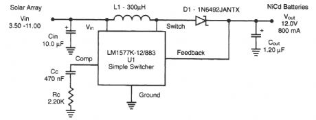
A National Semiconductor LM1577 IC is used in a step-up regulator to charge Nicad batteries from a solar panel. (View)
View full Circuit Diagram | Comments | Reading(2204)
BATTER_CHARGER
Published:2009/6/16 3:13:00 Author:May
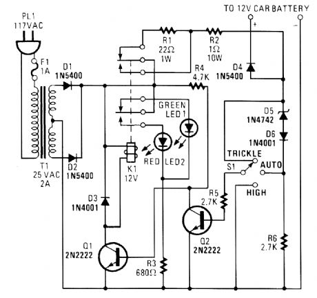
The circuit is capable of supplying either a trickle (50 mA) or high-current (1-A) charge. You can select either charging dtethod or an automatic mode that will first trickle charge a battery if it is particularly low before switching to high-current charging.If the battery's voltage is low, Zener-diode D5 will not conduct sufficient current to produce a voltage drop across R6 to turn Q2 on. With Q2 off, R4 pulls the base of Q1 high, turning it on. That activates K1. With K1 active, the only thing between the battery and the power supply is R2 and D4 (which prevents current from flowing through the circuit from the battery).Once the battery charges a bit, the current through D5 increases, causing a voltage drop across R6 that is of sufficient magnitude to turn on Q2. Transistor Q2, in turn, grounds the base of Q1, keeping it off. With Q1 off, K1 remains in its normally closed state. That places R1 in series with the battery, thereby reducing the current to a trickle. (View)
View full Circuit Diagram | Comments | Reading(1914)
RF_TYPE_BATTERY_CJARGER
Published:2009/6/16 3:08:00 Author:May
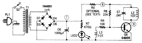
This type of charger couples RF from L2 to an external pickup coil The pickup coil connects to a rectifier and batteryto be charged This idea is handy because no wire or contacts are required L2 is 10T #24 wire and L3 is 10T #30 wire. Both cois are mounted on a 1''×1/4'' ferrite rod. (View)
View full Circuit Diagram | Comments | Reading(1149)
LEAD_ACID_TRICKLE_CHARGER
Published:2009/6/16 3:08:00 Author:May
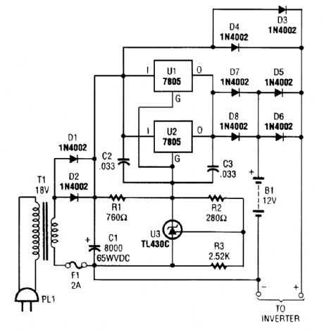
The charger can be used as a stand-alone charger or for emergency lighting and burglar alarm systems using lead-acid batteries. (View)
View full Circuit Diagram | Comments | Reading(1021)
ACTIVE_UNITY_GAIN_SECOND_ORDER_LOW_PASS_FILTER
Published:2009/6/16 3:05:00 Author:May
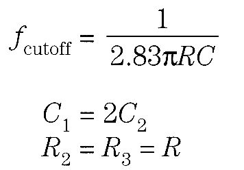
This second-order Butterworth filter cuts off near 10 kHz. The values of C1and C2 can be changed to alter the frequency, or else calculated from the formula.
(View)
View full Circuit Diagram | Comments | Reading(1278)
UNITY_GAIN_SECOND_ORDER_HIGH_PASS_FILTER
Published:2009/6/16 3:03:00 Author:May

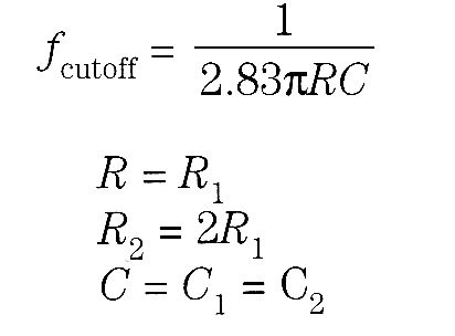

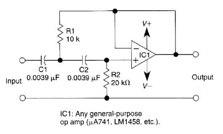
This filter circuit has a cutoff frequency of 2900 Hz with the values shown
(View)
View full Circuit Diagram | Comments | Reading(857)
1_mV_OFFSET,CLOCK_TUNABLE,MONOLITHIC_5_POLE_LOW_PASS_FILTER
Published:2009/6/16 3:02:00 Author:May
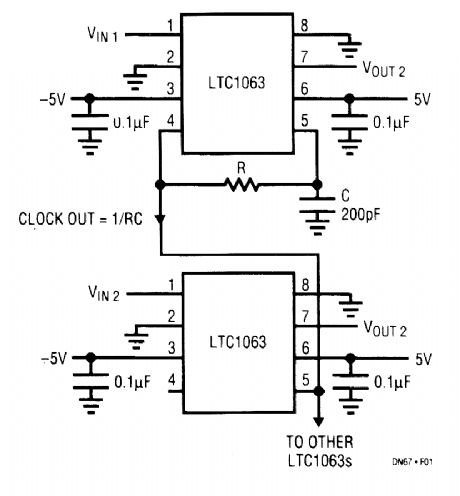
The LTC1063 is the first monolithic low-pass fil-ter that simultaneously offers outstanding dc and ac performance. It features internal or external clock tunability, cutoff frequencies up to 50 kHz, 1-mV typ-ical output dc offset, and a dynamic range in excess of 12 bits for over a decade of input voltage.The LTC1063 approximates a 5-pole Butterworth low-pass filter. The unique internal architecture of the filter allows outstanding amplitude matching from device to device. Typical matching ranges from 0.01 dB at 25% of the filter passband to 0.05 dB at 50% of the filter passband.An internal or external clock programs the filter's cutoff frequency. The clock-to-cutoff frequency ratio is 100:1. In the absence of an external clock, the LTC1063's internal precision oscillator can be used. An external resistor and capacitor set the device's internal clock frequency. (View)
View full Circuit Diagram | Comments | Reading(766)
HEADLIGHT_ALARM
Published:2009/6/16 3:01:00 Author:May
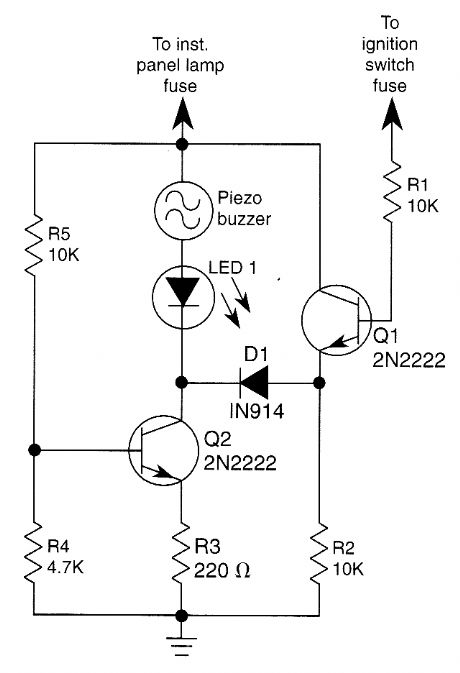
The base of Q1 is connected to the car's ignition circuit; the easiest point to make that connection is at the ignition switch fuse in the car's fuse panel. Also, one side of the piezoelectric buzzer is connected to the instrument-panel light fuse; when the headlights or parking lights are on, the instrument panel is lit, too. When the headlights are off, no current reaches the buzzer. Therefore, nothing happens. What happens when the head-lights are on depends on the state of the ignition switch. When the ignition switch is on, transistors Q1 and Q2 are biased on, effectively removing the buzzer and the LED from the circuit.When the ignition switch is turned off, but the headlight switch remains on, transistor Q1 is turned off, but transistor Q2 continues to be biased on. The result is that the voltage across the piezoelectric buzzer and the LED is sufficient to cause the buzzer to sound loudly and the LED to light. (View)
View full Circuit Diagram | Comments | Reading(386)
AUTO_FUSE_MONITOR
Published:2009/6/16 3:00:00 Author:May
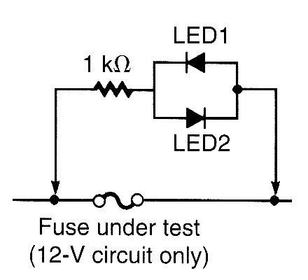
This circuit can quickly check a fuse in an automobile circuit. Connect across suspected fuse-either LED glows, fuse is blown. The circuit must be live for this test to work. (View)
View full Circuit Diagram | Comments | Reading(850)
LIGHTS_ON_REMINDER
Published:2009/6/16 3:00:00 Author:May
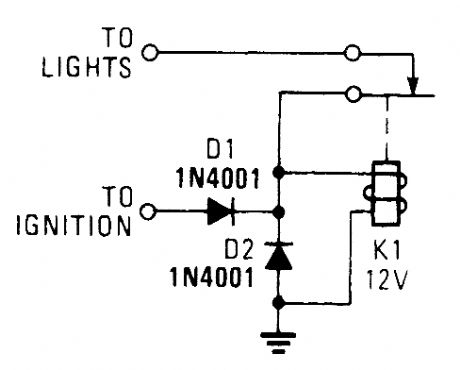
A relay and two diodes are all that is needed-the relay performs the job of a buzzer so no annun-ciator is required. When the lights are left on, but the ignition is off, the normally closed relay contacts are in series with the relay coil. That means the relay interrupts its own power each time it becomes active, so it chatters and acts fie a buzzer.This is a real minimalistic headlight reminder. It doesn't even require an annunciator because the relay acts as buzzer. (View)
View full Circuit Diagram | Comments | Reading(3)
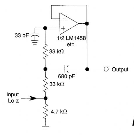
VARIABLE_HIGH_PASS_FILTER
Published:2009/6/16 2:54:00 Author:May
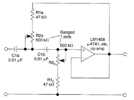
This second order filter which should prove useful in audio applications uses an LM1458 or other similar of op amp. It is tuneable from 30 to 300 Hz cutoff. R2a, b are ganged log-taper poten-tiometers. (View)
View full Circuit Diagram | Comments | Reading(985)
VARIABLE_LOUW_PASS_FILTER
Published:2009/6/16 2:53:00 Author:May
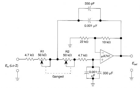
This second-order low-pass filter uses a 741 op amp and is tuneable from 2.5 kHz to 25 kHz.This circuit is useful in audio and tone control ap-plications. R1 and 2 are ganged potentiometers. (View)
View full Circuit Diagram | Comments | Reading(1672)
AUTO_GENERATOR_REGULATOR
Published:2009/6/16 2:53:00 Author:May
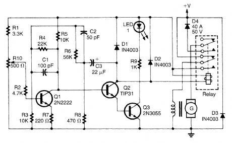
This regulator is for the purpose of controlling a dc generator. The field configuration is that one side of the field is grounded. D4 prevents the battery from discharging through the generator and takes the place of the mechanical cut-out relay. R10 adjusts the system voltage setting. (View)
View full Circuit Diagram | Comments | Reading(1)
VARIABLE_FREQUENCY_AUDIO_BP_FILTER
Published:2009/6/16 2:53:00 Author:May
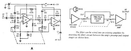
This variable-frequency, audio bandpass filter is built around two 741 op amps that are connected in cascade. Tro 741 op amps are configured as identical RC active filters and are connected in cascade for better selectivity. The filter's tuning range is from 500 Hz to 1500 Hz. The overall volt-age gain is slightly greater than 1 and the filter's is about 5. The circuit can handle input signals of 4 V peak-to-peak without being overdriven. The circuit's input impedance is over 200 kQ and its output impedance is less than 1 kQ. (View)
View full Circuit Diagram | Comments | Reading(2897)
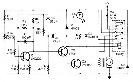
ALTERNATOR_REGULATOR
Published:2009/6/16 2:52:00 Author:May

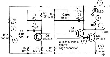
This alternator regulator uses a 3-transistor dc amplifier, and is designed for a pulled up field system, where one side of the alternate field returns to the +12-Vsupply, and the other end is pulled toward ground. The circuit monitors the state of the battery through a resistive divider and causes the voltage to change at the field terminal. (View)
View full Circuit Diagram | Comments | Reading(7850)
AUTOMATIC_TURN_OFF_CONTROL_FOR_AUTOMOBILES
Published:2009/6/16 2:49:00 Author:May
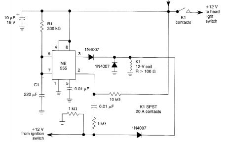
When the ignition switch is on, relay K1 is energized continuously, and the headlights can be Lumed on. Turning off the ignition turns on timer IC1,which keeps IC1 energized for a time deter-mined by R1 and C1. With the values shown approximately a 1 minute delay wilLresult. The values of R1 or C1 can ve changed to vary this delay time. (View)
View full Circuit Diagram | Comments | Reading(737)
| Pages:1441/2234 At 2014411442144314441445144614471448144914501451145214531454145514561457145814591460Under 20 |
Circuit Categories
power supply circuit
Amplifier Circuit
Basic Circuit
LED and Light Circuit
Sensor Circuit
Signal Processing
Electrical Equipment Circuit
Control Circuit
Remote Control Circuit
A/D-D/A Converter Circuit
Audio Circuit
Measuring and Test Circuit
Communication Circuit
Computer-Related Circuit
555 Circuit
Automotive Circuit
Repairing Circuit