
Circuit Diagram
Index 1787
S1AO903X01 single chip AM/FM digital tuner circuit
Published:2011/5/20 2:29:00 Author:Christina | Keyword: single chip, AM/FM, digital tuner
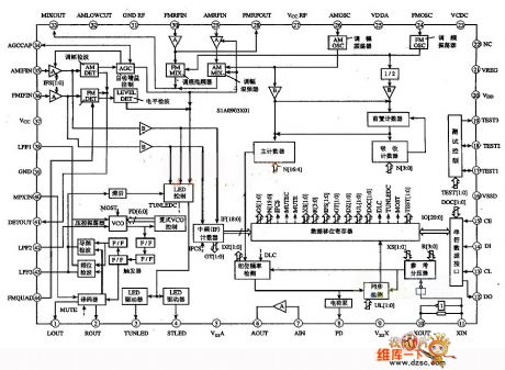
This circuit has three points of features:
(1)The amplitude modulation circuit includes the radio frequency (RF) circuit, the mixer (MIX), the oscillator (OSC), the intermediate frequency (IF) amplifier (AMP), the detector (DET), the automatic gain control (AFC) circuit, the tuning LED driver circuit, the oscillator and the IF buffer circuit.
(2)The tuning circuit includes the RF amplifier, the RF mixer, the oscillator, the IF amplifier, the tuning LED driver circuit, the IF amplifier, the tuning LED driver circuit.etc.
(3)The other circuits are: the PLL, the stereo decoding circuit, the multiple voltage-controlled oscillator (MPX VCO), the LED controller / driver, the AM/FM programmable mixer, the AM/FM IF counter.etc. The internal circuit block diagram is as shown in the figure.
(View)
View full Circuit Diagram | Comments | Reading(2759)
The high sensitivity loud sound alarm circuit
Published:2011/6/10 4:46:00 Author:qqtang | Keyword: high sensitivity, loud sound alarm
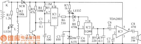
In the figure is the high sensitivity loud sound alarm circuit. This alarm is suitable for orchard security alarm systems. It is very sensitive and loud, so it has a good effect on the thieves, even if there are no guards in the orchard, the owners don't need to worry about their fruit, because the sound of catch the thieves will attract the people's attention and keep thieves away. The alarm is triggered by touch, once it was triggered, even linking the wires again is useless, the sound will be stopped in two minutes. The circuit is easy to make. (View)
View full Circuit Diagram | Comments | Reading(743)
LED zero beat display circuit
Published:2011/5/19 20:07:00 Author:Christina | Keyword: LED, zero beat, display circuit
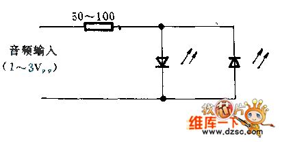
The two LEDs are connected with the opposite polarity, by the precision tuning of the receiver, the beat frequency can be displayed easily and intuitively. If the deviation of the beat frequency is above 1KHZ, the two LEDs are both blinking; if the deviation of the beat frequency is less than ±5HZ, the LED turns off. The luminous intensity of light emitting diode is decided by the audio amplifier low frequency response.
(View)
View full Circuit Diagram | Comments | Reading(1019)
DN-25 integrated circuit switching voltage-stabilized power supply circuit
Published:2011/5/19 19:32:00 Author:Christina | Keyword: switching, voltage-stabilized, power supply circuit
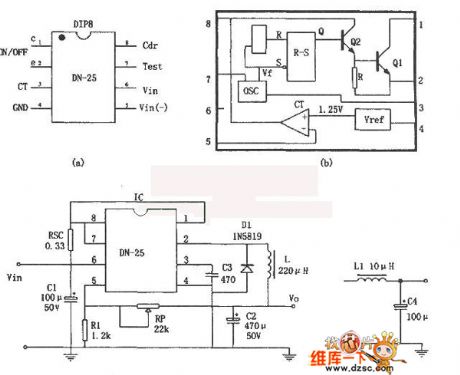
After startup, the oscillator starts working, the output VF signal is reshaped and transformed by R-S trigger to produce a original frequency rectangular pulse excitation voltage, and the VF signal is amplified by the darlington circuit which is composed of th Q1 and Q2 then output by pin-2. You can adjust the output voltage V0 by adjusting the voltage of comparator reversed-phase input terminal pin-5. By changing pin-5's voltage, we can adjust R-S trigger excitation pulse width, and cause the changing of the output voltage Vo. This voltage-stabilized power supply VIN=25V,Vo=(1+RP/XVREF), the stability is 0.12%; the load regulation is 0.03%; the short-circuit limit current is IOSH=1.1A; the efficiency is η=82.50%; the ripple wave is less than 120mVp-p.
(View)
View full Circuit Diagram | Comments | Reading(951)
Watt-hour meter LCD driving control integrated circuit SM9913 typical application circuit
Published:2011/5/19 19:12:00 Author:Christina | Keyword: Watt-hour meter, LCD, driving control, integrated circuit, typical application circuit
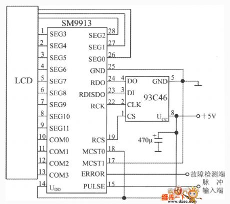
The watt-hour meter LCD driving control integrated circuit SM9913 typical application circuit is as shown. The E2PROM uses the 93C46 type 64×16b electrical erase programmable memory. The SM9913's ERROR output port can be used to test or read the data error and the internal data processing error of E2PROM, it outputs the low level voltage. It will outputs the high level voltage in following circumstances:1.Writing E2PROM data error or reading E2PROM data error; 2.Working process display data writing internal registers error; 3.Internal trigger is not working properly.
(View)
View full Circuit Diagram | Comments | Reading(1984)
Manostat power supply composed of the L296 large current switching power supply chip
Published:2011/5/19 18:48:00 Author:Christina | Keyword: Manostat power supply, large current, switching power supply chip
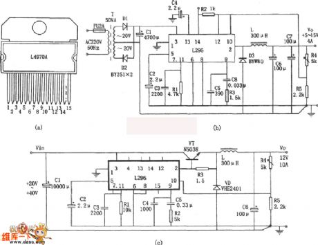
The Manostat power supply which is composed of the L296 large current switching power supply chip is as shown. a, b and c are the 5~15V, 4A manostat power supply which is composed of the L296 monolithic large current switching power supply chip. Features of the L296 monolithic large current switching power supply chip are: (1)Perfect protecting function. (2)The maximum output current is 4A, power is 160W, the output voltage is between 5.1~40V. (3)With special functions such as the working prohibition control, the synchronous control, the reset circuit and the stich over-voltage protection circuit. The figure c shows the form of current expansion circuit.
(View)
View full Circuit Diagram | Comments | Reading(5144)
Using Constant-Voltage Current-Limited Floating-Charge Method Power-Outage Lighting Circuit
Published:2011/5/20 0:05:00 Author:Robert | Keyword: Constant-Voltage, Current-Limiting, Floating-Charge, Power-Outage, Lighting
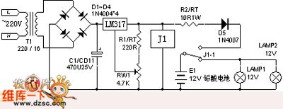
The commercial power would be changed to output 15.1V constant DC voltage through t1's step-down, d1~d4's rectifier, c1's filter and the lm317's regulator. The relay J1 is connected to make the r2, d5 process the current-limited floating charge to the battery. This would make sure the battery in full energy mode anytime. When the commerical power have a outage, j1 would be disconnected and the 12V lead-acid battery begins to supply to the lamps for emergency lighting. The 12V lead-acid battery's floating charging voltage is 14.4V. Because of the diode D5 has been connected in to prevent back discharge, it should adjust the rw1 to make the output voltage of lm317 be 15.1V. This could make sure the battery has enough voltage.
(View)
View full Circuit Diagram | Comments | Reading(1208)
555 Multi-Wave Generator Circuit (1)
Published:2011/5/19 8:03:00 Author:Robert | Keyword: Multi-Wave, Generator
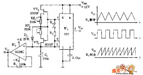
As shown, this circuit is a multivibrator oscillator made up by 555, C1 and constant current charging and discharging circuit. Thc IC2 uses 5G28C as a high-impedance follower device to play the role of isolation and impedance transformation. The oscillator's charging and discharging are all for the constant current source. So its sawtooth wave has a good linearity. RP1 and RP2 are used to adjust the time constant of charging or discharging and the duty ratio separately.
The parameter shown in the picture's cycle time is 0.2ms~60s. When the K1 is disconnected, it would generate sawtooth wave whose cycle is a half of the triangle wave's.
(View)
View full Circuit Diagram | Comments | Reading(2369)
MIC Bias Circuit-1.5km Single-Tube FM Radio MIC Transmitter Circuit
Published:2011/6/10 21:34:00 Author:Robert | Keyword: MIC, Bias Circuit, 1.5km, Single-Tube, FM, Transmitter
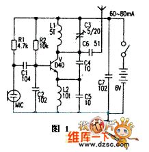
The picture 1 is a typical 1.5km single-tube FM radio MIC transmitter circuit. This circuit's key components is emission triodes which always are the D40, D50, 2N3866 and so on. Its working circuit is 60-80mA.
In amateur case it is easy to make a successful low-power radio circuit with 88~108MHz FM frequency range. This circuit has sinple single-tube transmitter circuit and also uses the integrated stereo transmitter circuit. It is mainly used for FM radio headset, wireless telephone recording forwarding, remote control, wireless alarm, monitoring, data ransmission and campus FM radio and so on.
(View)
View full Circuit Diagram | Comments | Reading(2960)
555 sound control floodlight circuit
Published:2011/5/21 23:08:00 Author:TaoXi | Keyword: sound control, floodlight
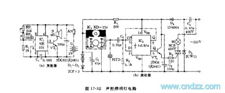
As the figure 17-49 shows, the sound control circuit is composed of two parts: the transmitter and the receiver.
The astable multivibrator is composed of the 555 and RP1,RP2,R1,C1, the oscillation frequency f=1.44/(RP+2R1)C1, the parameters in the figure have the oscillation frequency of about 1~40kHz, the oscillation frequency is adjustable. It drives the high-pitched loudspeaker through VT1. The IC1 of the receiving circuit uses the special whistle integrated circuit KD-154, and the KD-154 is very sensitive to the high voice frequency of 18kHz, when debugging, we adjust RP1 and RP2 to send out the 18kHz audio frequency to drive the KD-154. The HTD is the pickup.
(View)
View full Circuit Diagram | Comments | Reading(520)
555 sound control color light circuit
Published:2011/5/21 22:41:00 Author:TaoXi | Keyword: sound control, color light
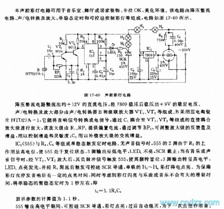
This sound control color light circuit can be used in wide range of applications such as the music room, the dance hall or the karaoke, the home decoration. This circuit is composed of the step-down rectifier circuit, the sound/electricity conversion and amplifying circuit, the monostable timing circuit and the SCR color light control circuit. The circuit is as shown in figure 17-60.
The monostable trigger timing circuit is composed of the IC1(555) and R4,C4. When there is no signal, pin-2 of 555 has the high level voltage because of R2's lifting effect, so 555 is in the reset-state, pin-3 has the low level voltage, LED1 turns off, SCR cuts off; when there is the music or sound signal, this signal is amplified by VT1 and VT2, the negative pulse signal triggers 555, pin-3 outputs the high level voltage, LED1 turns on.
(View)
View full Circuit Diagram | Comments | Reading(625)
555 three colors flash light circuit
Published:2011/5/21 22:27:00 Author:TaoXi | Keyword: three colors, flash light
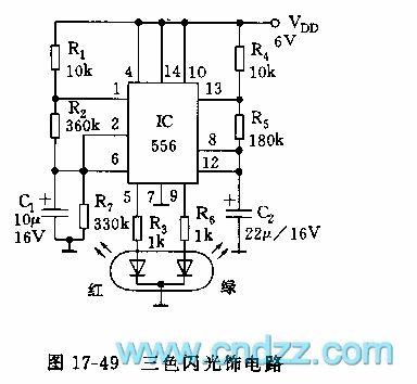
As the figure 17-49 shows, the circuit is composed of the 556 and a dual core light tube. The 2Hz multivibrator is composed of the IC's left part (1/2 556) and the R1,R2,C1.etc; The 0.5Hz multivibrator is composed of the IC's right part (1/2 556) and the R4,R5,C2.etc. The pin-5 and pin-9 of the output port drive the red diode and the green diode to turn on, so we have the three color flash (red, freen and orange), the brightness dazzles the eyes.
(View)
View full Circuit Diagram | Comments | Reading(726)
555 neon light high-frequency high-voltage source circuit
Published:2011/5/21 22:14:00 Author:TaoXi | Keyword: neon light, high-frequency, high-voltage, source circuit
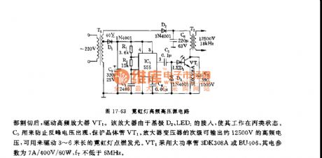
This power supply uses one piece of the time base circuit 555 as the core. The circuit is as shown in figure 17-63.
The multivibrator is composed of the 555 and R1,R2,C2, the oscillation frequency f=1.44/(R1+2R2)C2
The oscillation frequency of the parameters in the figure is 17.8kHz, the output pulse's duty cycle is about 1:1. The output of 555 is cut by D3 and then drives the high frequency amplifier VT1. This amplifier connects with the base electrode D3 and the LED1, so it's working condition is C-class. C5 can be used to prevent the reverse peak voltage, and it protects the transistor VT1. The secondary stage of the amplifier transformer can output the high-frequency voltage of 12500V, and this voltage can turn on the 3 ~ 6 meters neon light.
(View)
View full Circuit Diagram | Comments | Reading(1275)
555 brightness adjustable indicator light circuit
Published:2011/5/21 9:33:00 Author:TaoXi | Keyword: brightness, adjustable, indicator light
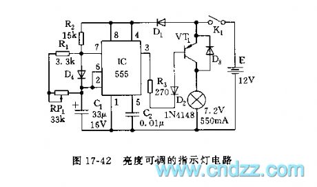
In some conditions we need the brightness adjustable indicator light, if we uses the resistance step-down method, the power consumption is large. This circuit uses the variable duty cycle oscillation square-wave to supply power, this method can adjust the brightness of the light, and can save the power.
As the figure 17-42 shows, the astable multivibrator is composed of the 555 and R1,R2,RP1,C1. The oscillation periods are:
T=0.0693(R1+R2+RP1)C1t(charging)=0.693R2C1t(discharging)=0.0693(R1+RP1)C1
By adjusting RP1, we can change the t(discharging) which means the lighting time of the lamp.
(View)
View full Circuit Diagram | Comments | Reading(595)
555 mobile light program controller circuit
Published:2011/5/21 8:30:00 Author:TaoXi | Keyword: mobile light, program controller
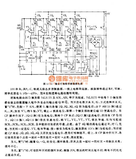
As the figure 17-55 shows, the program controller is composed of the clock generation circuit, the logic circuit and the SCR control circuit.etc. And this circuit can be used in the program control of the advertising lights and mobile lights.
The astable multivibrator is composed of the 555 and R1,RP1,C1. The oscillation frequency is adjusted by the RP1, the frequency range is between 0.5Hz to 45Hz. And this astable multivibrator is used to control the logic control circuit's cycle.
The logic circuit is composed of the 4-D trigger 74LS175 and the switches such as AN1 and AN2. Every D trigger of 74LS175 has independent data input port D and output port Q. When you open the power supply switch K1, and the mode selection switch K2 is in the position 1 , and then you press AN1 to make K2 to 0, the output ports 1Q,2Q,3Q and 4Q all have the low level voltage.
(View)
View full Circuit Diagram | Comments | Reading(731)
555 film cans-show lan activity & exposure timer circuit
Published:2011/5/21 8:12:00 Author:TaoXi | Keyword: film, cans-show, lan activity, exposure, timer circuit
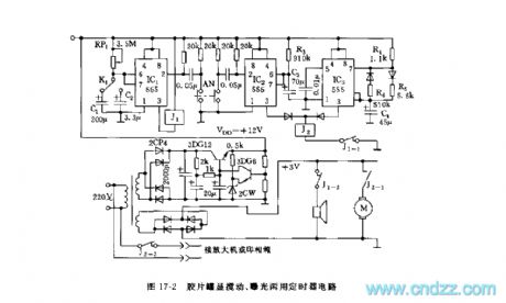
As the figure 17-2 shows, the step-down rectifying power supply spllies the voltage of VDD=+12V to the timer. The timer uses three pieses of 555 as the core. IC1 is the long timing circuit, when you press AN, IC1 and IC2 reset together, IC1's timing time is td1=1.1RP1C1,td2=1.1RP1C2, and the value depends on the different films and different exposure time. When the warning time is up, J1-1's NC contact point cuts off, IC2 and IC3's power supplies are cut off. The 1 minute timer is composed of the IC2 and R3,C3, when you press AN, J2 closes to connect the J2-1.
(View)
View full Circuit Diagram | Comments | Reading(586)
555 simple practical music light control circuit
Published:2011/5/21 7:07:00 Author:TaoXi | Keyword: simple, practical, music lights, control circuit
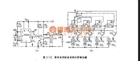
As the figure 17-53 shows, this circuit is composed of the sound control multivibrator, the timing pulse generator and the SCR trigger circuit.etc.
The astable multivibrator is composed of the 555 and R2, RP1, R3, C3.etc. The music signal is detected by the coupling transformers T1 and D1, and it is amplified by VT1, then it adds to the 555's control port pin-5. Pin-5 connect with the standard partial pressure point (2/3VDD) of the integrated chip's internal comparator.
This circuit can produces five kinds of cycle way to make the flash to change with the music, so it can be used in the dance floors or the celebration occasions.
(View)
View full Circuit Diagram | Comments | Reading(707)
555 simple printing & amplification timer circuit
Published:2011/5/21 6:43:00 Author:TaoXi | Keyword: simple, printing, amplification, timer circuit
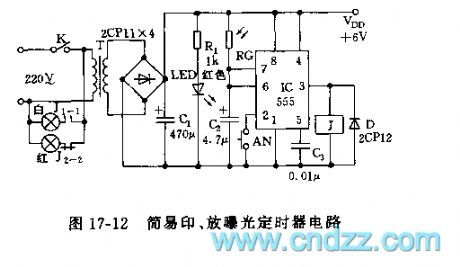
As the figure 17-12 shows, the timer is composed of the step-down rectifier circuit and the monostable circuit.
The monostable timing circuit is composed of the 555 and the C2, the photoresistor RG, when using, you need to press AN, the 555 sets, J1-1 connects, the white light turns on. The light shine on the RG through the film, according to the film's transmittance, RG presents the different resistances, so the monostable delays are different too. The delay time td=1.1RGC2. When the temporary stability time is up, J releases, the white light turns off, the red light turns on, so the automatic exposure is finished.
(View)
View full Circuit Diagram | Comments | Reading(574)
555 simple printing phase timing circuit
Published:2011/5/21 6:18:00 Author:TaoXi | Keyword: simple, printing phase, timing circuit
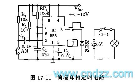
As the figure 17-11 shows, the monostable delay circuit is composed of the 555 and RP1,C1.etc. Every time when you print, because the voltage of C2 can not abrupt change, as a negative pulse adds to the pin-2 of IC, 555 sets, J closes, the light turns on. At the same time, the timing begins. After C1 is charged to 2/3VDD, 555 reverses, pin-3 has the low level voltage, the timing is over. The delay time td=1.1RP1C1. The parameter's maximum delay time in the figure is about 5 seconds. You need to adjust RP1 to the appropriate printing phasetime.
(View)
View full Circuit Diagram | Comments | Reading(659)
555 simple exposure timer circuit
Published:2011/5/21 5:58:00 Author:TaoXi | Keyword: simple, exposure timer
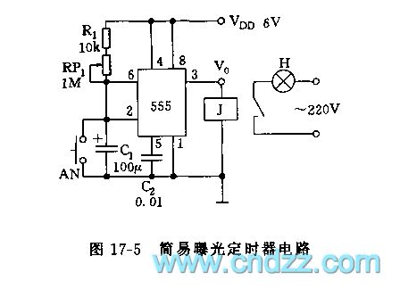
As the figure 17-5 shows, the photo exposure timer circuit uses the 555 as the core. This circuit is one kind of artificially start monostable circuit. If you press AN, the timing capacitor C1 immediately discharges to zero, 555 sets, the timing begins, J closes, the light H turns on. The lighting time is the time of C1 charges to 2/3VDD td=1.1(R1+RP1)C1. The length of time can be set by the photo typy. When the time is up, 555 returns to the reset state, pin-3 has the low level voltage, J releases, H turns off automaticly. The parameter's td in the figure is about 2 minutes.
(View)
View full Circuit Diagram | Comments | Reading(1067)
| Pages:1787/2234 At 2017811782178317841785178617871788178917901791179217931794179517961797179817991800Under 20 |
Circuit Categories
power supply circuit
Amplifier Circuit
Basic Circuit
LED and Light Circuit
Sensor Circuit
Signal Processing
Electrical Equipment Circuit
Control Circuit
Remote Control Circuit
A/D-D/A Converter Circuit
Audio Circuit
Measuring and Test Circuit
Communication Circuit
Computer-Related Circuit
555 Circuit
Automotive Circuit
Repairing Circuit