
Circuit Diagram
Index 1792
active filter circuit
Published:2011/6/3 19:56:00 Author:chopper | Keyword: active filter
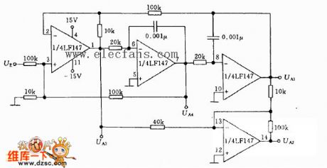
Its core frequency fo=3.4kHz,notch frequency fc=9.5kHz,quality factor Q=3.4.AS for high frequency filter,coefficient of transmission is 0.1;as for band-pass filter,the coefficient is 1;as for low frequency filter,the coefficient is 1;as for low amplitude filter,the coefficient is 1; as for notch filter,the the coefficient is 10.foQ≤200KHz.When output string signal is within 10V,its highest frequency is not more than 200KHz.
(View)
View full Circuit Diagram | Comments | Reading(673)
The voice distress box of patient faintness
Published:2011/6/3 23:47:00 Author:Seven | Keyword: voice distress box, patient faintness
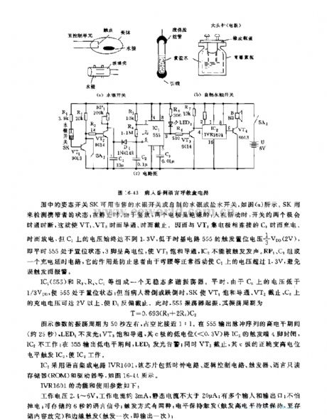
In the figure, the carriage switch SK can be used in mercury switches in the market and self-made mercury or salty water switches, see as figure a. SK is used to test the state of the taker: when it is still, as it is put vertically, the two electric poles are insulated; when the people are moving, the two poles are on and off now and then, which makes VT1 and VT2 conducting and blocked now and then. Therefore, the CI, which is linked with VT2 pole, charges and discharges now and then, but the voltage on C1 can reach 1.3v all the time which is lower than the offset triggering LEV of 1/3 VDD(2v) of the time-based circuit(555).
(View)
View full Circuit Diagram | Comments | Reading(572)
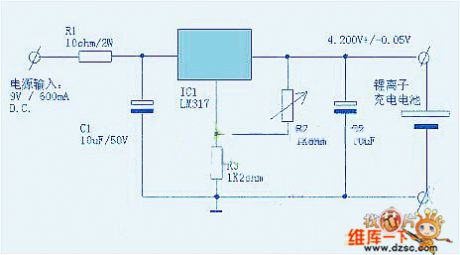
The simplest lithium battery charger circuit
Published:2011/6/3 20:03:00 Author:chopper | Keyword: lithium battery charger
View full Circuit Diagram | Comments | Reading(1430)
The integration design circuit of infrared CCD signal processing
Published:2011/6/3 20:22:00 Author:chopper | Keyword: integration design circuit, infrared CCD signal processing
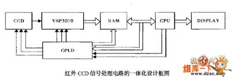
The CCD signal processing integration design can reduce volume,reduce the noise of circuit and improve signal-to-noise ratio. Due to features of high integration,software programming,easy to modify,completely simulation with CPLD,the CPLD applies to the CCD driver timing and other interface control signals in order to reach the miniaturization,debugging and upgrade of cirucit. (View)
View full Circuit Diagram | Comments | Reading(498)
The linear plat temperature adjuster
Published:2011/6/4 0:32:00 Author:Seven | Keyword: temperature adjuster
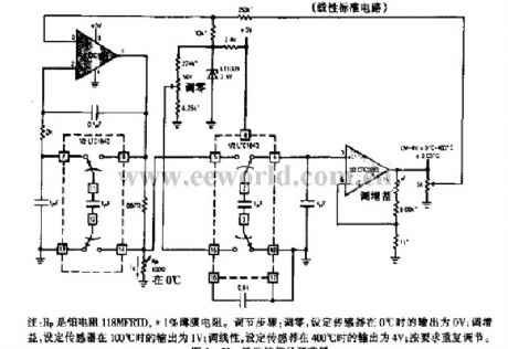
Notes: Rp is the plat resistance 118MFRTD, *1% thin film resistance. Adjusting process: setting to zero, set the output of the sensor to be 0v when it is 0℃; gain adjusting, set the output voltage of the sensor to be 1v when it is 100℃; linearity adjusting, the output of the sensor is set to be 4V when it is 400℃; adjust repeatedly accordingly. (View)
View full Circuit Diagram | Comments | Reading(618)
The light control toy car of KD-28
Published:2011/6/3 2:37:00 Author:Seven | Keyword: light control, toy car
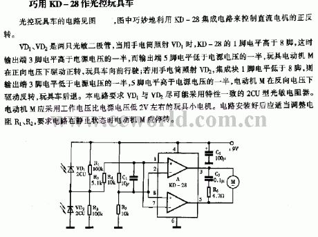
VD1 and VD2 are two light dependent resistors, when VD1 is lighted by a torch, the LEV of the 1-pin of KD-28 is higher than 8-pin, at that moment, the LEV of the output terminal, the 3-pin, is high than the half of the power supply, but the LEV of 5-pin is lower than that, and the toy motor M is rotating forward by the drive of the forward voltage, so the toy car runs forward; if the VD2 is lighted by a torch, the LEV of the 1-pin of the integrated chip is lower than 8-pin, so the LEV of the output terminal,3-pin, is lower than the half of the power supply, and that of 5-pin is higher than half of the power supply, the motor rotates forward.
(View)
View full Circuit Diagram | Comments | Reading(571)
the principle of zero-crossing comparison and phase comparison circuit
Published:2011/6/8 20:32:00 Author:chopper | Keyword: principle, zero-crossing comparison, phase comparison
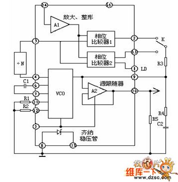
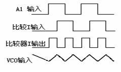
The phase-locked loop CD4046 in common usage of integrated circuit is a universal CMOS PLL integrated circuit.Its feature is that its supply voltage ranges widely(3V-18V)and the input impedance is high(about 100MΩ),dynamic power consumption is low.When the core frequency f0 is 10KHZ,the power consumption is just 600μW and it is a micro-power module.The following picture is the pins arrangement of CD4046 and it adopts 16 feet dual inline type. The functions of pins is as follows.
(View)
View full Circuit Diagram | Comments | Reading(974)
The contactless fancy lantern controller circuit
Published:2011/6/2 8:30:00 Author:Seven | Keyword: contactless, fancy lantern
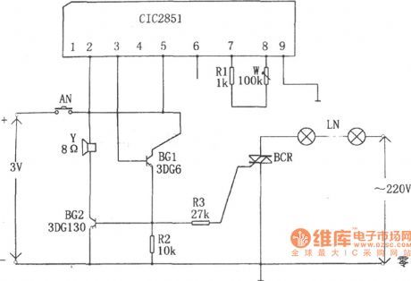
When the switch of AN is pressed, CIC2851 is triggered to work, the output terminal (3-pin) launches music signals. After the music signals are BG1 and BG2 is magnified, the loudspeaker makes music. In the meantime, the dual controllable silicon SCR is conducting and the fancy lantern is glowing with the change of the music. By adjusting W, the performing time of the circuit is changed, i.e the flashing time of the fancy lantern is changed.
(View)
View full Circuit Diagram | Comments | Reading(585)
TD-5 ultrasonic micro fogging humidifier
Published:2011/6/5 12:46:00 Author:Seven | Keyword: fogging humidifier
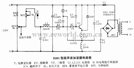
T:Power supply transformer FU:Fuse VT:Triode L1,L2 and L3: inductor B: Piezoelectric pottery power shifter S-N:magnet ring floater SL: water level switch RP1:fog content adjusting potentiometer RP2: adjustable resistor (View)
View full Circuit Diagram | Comments | Reading(2133)
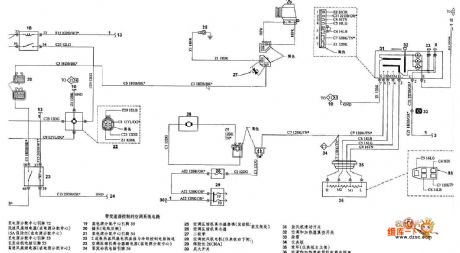
Dodge air-conditioning without transmission circuit
Published:2011/6/8 20:12:00 Author:chopper | Keyword: Dodge, air-conditioning, transmission

View full Circuit Diagram | Comments | Reading(752)
Dodge air-conditioning with transmission control circuit
Published:2011/6/8 7:29:00 Author:chopper | Keyword: Dodge, air-conditioning, transmission control
View full Circuit Diagram | Comments | Reading(739)
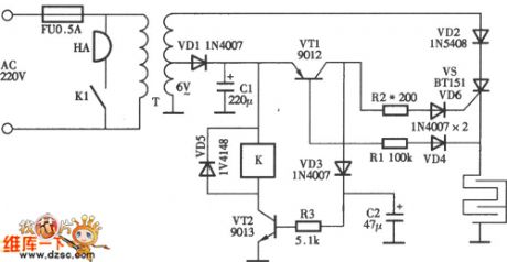
electronic mouse trap circuit
Published:2011/6/8 7:28:00 Author:chopper | Keyword: electronic, mouse trap
View full Circuit Diagram | Comments | Reading(5713)
AP3012 positive and negative voltage production circuit
Published:2011/6/8 7:27:00 Author:chopper | Keyword: positive, negative, voltage production

View full Circuit Diagram | Comments | Reading(1344)
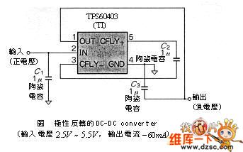
DC-DC with polarity inversion circuit
Published:2011/6/6 9:58:00 Author:chopper | Keyword: DC-DC, polarity inversion
View full Circuit Diagram | Comments | Reading(695)
electronic filter circuit
Published:2011/6/8 6:48:00 Author:chopper | Keyword: electronic filter
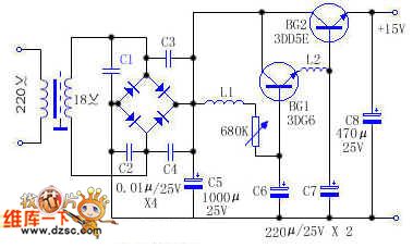
BG1 and BG2 form mulriple pipe.This circuit adds the filter element to the base of mulriple pipe which is different from others. The magnification coefficient of mulriple pipe β=β1•β2,so the filtering effect obtained from BG2 emitter is β1 times over L1 and C6,which equals that the big capacitance and inductance are added to the circuit.The most of hum in the circuit is restrained.And because the circuit adds L2 and C7 as well,their filtering effect was expanded β2 times by BG2,and leaches residual hum further.
(View)
View full Circuit Diagram | Comments | Reading(707)
Bandpass filter circuit
Published:2011/6/6 10:16:00 Author:chopper | Keyword: Bandpass filter
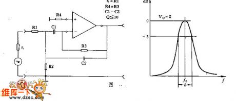
This circuit should determine the value of the R1 aforehand which is similar to the signal source resistance r1/ The principle of parameter selection is R4 = R3,C1 equals to C2 approximately,and Q equals to or lesser than R1,500K>R>1K,0.5uF>C>200pF.
(View)
View full Circuit Diagram | Comments | Reading(635)
Dodge postheating cirucit
Published:2011/6/8 6:49:00 Author:chopper | Keyword: Dodge, postheating

View full Circuit Diagram | Comments | Reading(592)
The infrared receiver circuit
Published:2011/6/3 0:37:00 Author:Seven | Keyword: infrared receiver
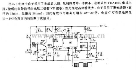
Because of the integrated amplifier, the circuit in Figure 8.5 is simple and small-sized. It is fixed with a TDA4050 integrated circuit, the weak infrared signal is received by the light dependent diode VD, and the signal is magnified by the NPN firstly. As the condensing (of which the diameter is about 15mm, and the focal length is about 30mm)lens is used here, the effective distance is increased to 20-30 times more than the former. The capacitor C can effectively reduce the low-frequency noise signal in the range of 50-100HZ.
(View)
View full Circuit Diagram | Comments | Reading(824)
The Fahrenheit(F) thermometer circuit
Published:2011/6/3 0:26:00 Author:Seven | Keyword: Fahrenheit(F) thermometer
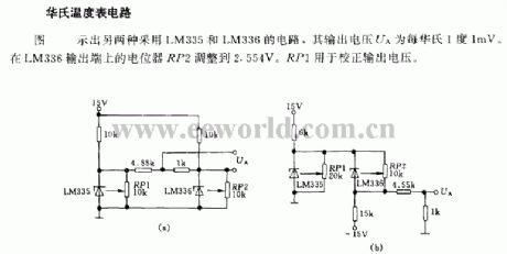
In the figure, there are two kinds of LM335 and LM336 circuit, whose output voltage UA is 1mv/1F.The potentiometer RP2 on the output terminal of LM336 is adjusted to 2.554v, and RP1 is used to adjust the output voltage.
(View)
View full Circuit Diagram | Comments | Reading(890)
The practical crystal test circuit
Published:2011/6/1 20:33:00 Author:Seven | Keyword: crystal, test circuit

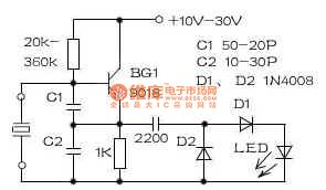
The writer has made a crystal test circuit of 10KHZ~1000MHZ with several simple elements(see as the figure). BG1 and its connected RC form a multi-frequency oscillator, after C3,D1 and D2 test the wave, the LED will get a voltage, and the polarity of the upper part is negative and the lower is positive, which drive the LED glow. If the crystal is broken and the LED is not glow, then we can install the circuit in the repairing power supply and leave two holes for the test elements. Notice: the two wires, which are led out from the crystal, can be too close to each other, or the oscillating amplitude will be reduced and the LED won't glowing.
(View)
View full Circuit Diagram | Comments | Reading(1246)
| Pages:1792/2234 At 2017811782178317841785178617871788178917901791179217931794179517961797179817991800Under 20 |
Circuit Categories
power supply circuit
Amplifier Circuit
Basic Circuit
LED and Light Circuit
Sensor Circuit
Signal Processing
Electrical Equipment Circuit
Control Circuit
Remote Control Circuit
A/D-D/A Converter Circuit
Audio Circuit
Measuring and Test Circuit
Communication Circuit
Computer-Related Circuit
555 Circuit
Automotive Circuit
Repairing Circuit