
Circuit Diagram
Index 1793
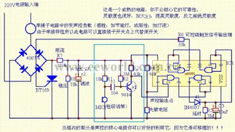
the sound controlled core circuit
Published:2011/6/3 7:21:00 Author:Seven | Keyword: sound controlled
View full Circuit Diagram | Comments | Reading(545)
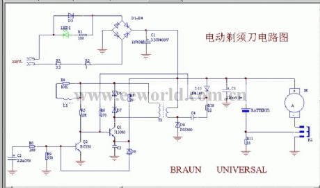
The imported electric razor circuit
Published:2011/6/3 6:56:00 Author:Seven | Keyword: electric razor
View full Circuit Diagram | Comments | Reading(1320)
The classical high-frequency head circuit
Published:2011/6/3 7:16:00 Author:Seven | Keyword: high-frequency
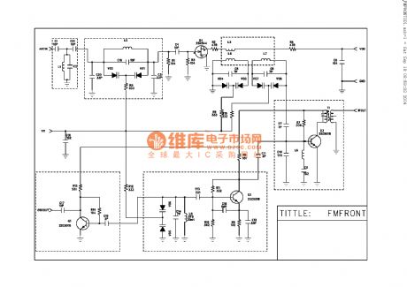
The classical high-frequency head circuit,FM, it is only for reference, the parameter of the element is self-decided. (View)
View full Circuit Diagram | Comments | Reading(893)
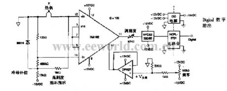
The separation thermocouple circuit of compensation
Published:2011/6/3 7:19:00 Author:Seven | Keyword: separation thermocouple
View full Circuit Diagram | Comments | Reading(551)
The low-cost air-conditioning MPUH of PIC16C54
Published:2011/6/3 6:49:00 Author:Seven | Keyword: air-conditioning MPUH
View full Circuit Diagram | Comments | Reading(712)
The principle circuit of classical Motorola L7 cellphone (3/7)
Published:2011/6/3 7:05:00 Author:Seven | Keyword: principle circuit, Motorola
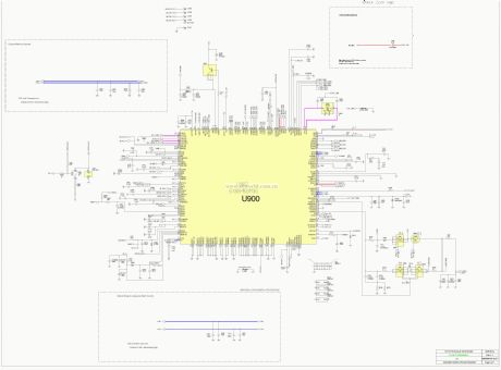
View full Circuit Diagram | Comments | Reading(552)
The principle circuit of classical Motorola L7 cellphone (4/7)
Published:2011/6/3 7:07:00 Author:Seven | Keyword: principle circuit, Motorola
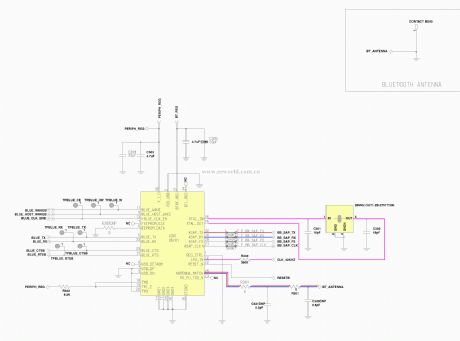
View full Circuit Diagram | Comments | Reading(578)
Field Frequency Identification Unit Circuit Diagram
Published:2011/6/9 4:20:00 Author:Vicky | Keyword: Field Frequency Identification Unit,
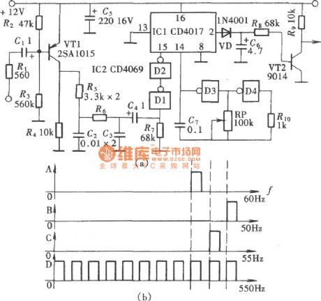
(View)
View full Circuit Diagram | Comments | Reading(606)
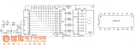
Three Digit Capacitance Circuit Diagram
Published:2011/6/9 4:29:00 Author:Vicky | Keyword: Three Digit Capacitance,
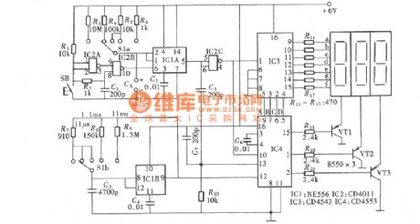
Three digit capacitance as shown in the picture is composed of basic pulse generator, gated circuit, control gate ,counter and decoding display.
The compositionand relation ofthe measuring range of every capacitancerating :
(View)
View full Circuit Diagram | Comments | Reading(967)
Bridge Rectifier Demonstrator Circuit Diagram
Published:2011/6/9 4:26:00 Author:Vicky | Keyword: Bridge Rectifier Demonstrator Circuit,
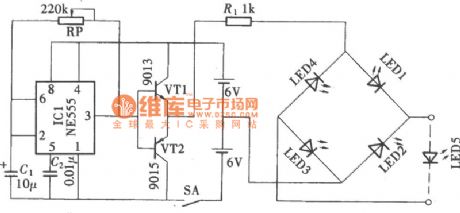
Bridge rectifier demonstrator circuit is a AC/DC conversion circuit. Bridge rectifier demonstrator circuit shown as in the picture reveals how the two groups of communication diode works in turn in the bridge rectifier circuit. It is made of pulse generator circuit, current direction control circuit, demonstrator circuit and power supply. (View)
View full Circuit Diagram | Comments | Reading(1328)
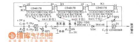
Arbitrary Number Pulse Circuit Diagram
Published:2011/6/9 3:53:00 Author:Vicky | Keyword: Arbitrary Number Pulse,
(View)
View full Circuit Diagram | Comments | Reading(589)
Internal Circuit Diagram of LM2931 Integrated Circuit
Published:2011/6/9 3:54:00 Author:Vicky | Keyword: LM2931 Integrated Circuit,
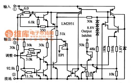
Functions and Characteristics
The Interior of LM2931 Integrated Circuit is mainly made of over-current protection circuit, over-voltage protection circuit and over-heat protection circuit, and it has the function of automatically stopping output when the power supply is reversed. The internal circuit diagram of LM2931 integrated circuit is as shown in the picture. (View)
View full Circuit Diagram | Comments | Reading(1093)
Digital Level Monitor Circuit Diagram
Published:2011/6/9 4:05:00 Author:Vicky | Keyword: Digital Level Monitor,
As is shown in the picture, digital level monitor can display the outgoing sound volume of sound amplifier by numbers. Because it adopts one digit display tube, the level it can display is from 1 to 9. (View)
View full Circuit Diagram | Comments | Reading(1047)
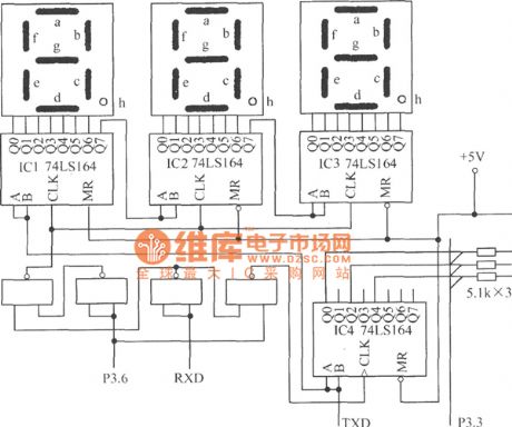
Sixteen Channels Digital Display Auto-patrol Circuit Diagram
Published:2011/6/9 4:08:00 Author:Vicky | Keyword: Sixteen Channels Digital Display Auto-patrol,
(View)
View full Circuit Diagram | Comments | Reading(642)
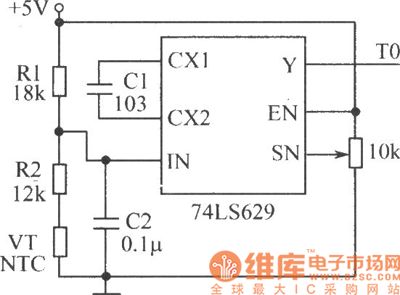
Ceramic Crystal Detector Circuit Diagram
Published:2011/6/9 4:08:00 Author:Vicky | Keyword: Ceramic Crystal Detector
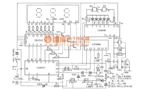
Ceramic crystal is crystal-type oscillator component used by infrared remote control launcher. The spoilage rate is comparatively high , and it is usually difficult to judge whether it is good or not in repairing. The detector as shown in the picture can quickly determine whether good or bad, which provides great convenience for repairing. The ceramic crystal detector actually is a three digit explicit frequency indicator, and the unit is KHz. (View)
View full Circuit Diagram | Comments | Reading(745)
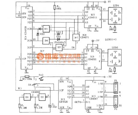
Reaction Capability Tester Circuit Diagram
Published:2011/6/9 4:00:00 Author:Vicky | Keyword: Reaction Capability Tester, CD4017
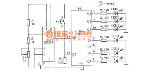
Reaction Capability Tester is used to test and train man’s quick-response capability. It has various type of construction and the Reaction Capability Tester as shown in the picture is composed of decimal counter CD4017 and luminous diode. The construction of Reaction Capability Tester is simple and can be used as a plaything to train and test children’s quick- response capability. (View)
View full Circuit Diagram | Comments | Reading(1541)
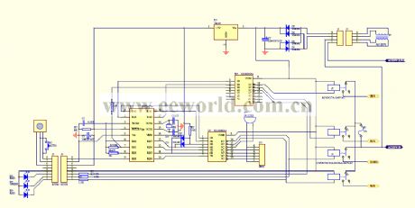
The beverage temperature controller circuit of fast heating and cooling
Published:2011/6/9 21:56:00 Author:qqtang | Keyword: beverage temperature controller, fast heating and cooling
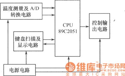
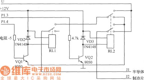
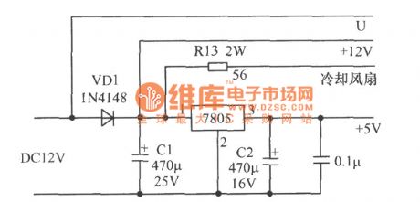
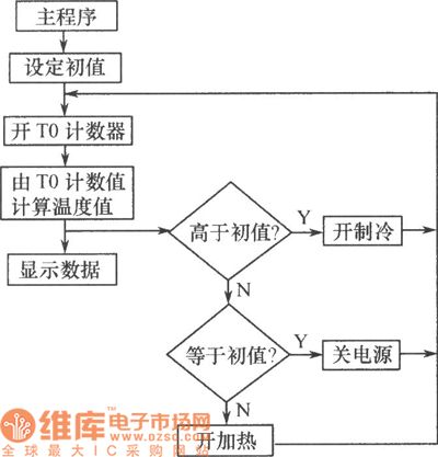
The hardware of the temperature control system consists of temperature measuring and A/D switch circuit, signal test and process circuit, key scanning and displaying circuit, control output circuit and power supply circuit and so on. The circuit is shown in the figure.(1) signal test and process circuit: the core of the temperature controller is the high quality-price ratio 8-bit micro-controller AT89C2051, which is used to complete the data measuring and processing, so that it can fulfill the measure and control function of the beverage temperature.(2) temperature measuring and A/D switch circuit
(View)
View full Circuit Diagram | Comments | Reading(887)
The schematic diagram of LCD digital displayer construction
Published:2011/6/9 22:06:00 Author:qqtang | Keyword: schematic diagram, LCD digital displayer
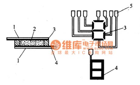
LCD displayer is also called LCD digital displayer, whose construction is shown in the figure. The main material of LCD displayer is liquid crystal(abbreviated as LC) which is a organic material, in certain temperatures, it not only has the mobility of the liquid, but also has the light character, its transparence changes with the electric field, magnetic field, light, temperature and other outside conditions. Therefore, under the effect of the logic circuit output signals, it can indicates some certain numbers. LCD displayer is a passive displaying element.
(View)
View full Circuit Diagram | Comments | Reading(1116)
BA6104--the 5 bit LED potentiometer drive integrated basic application circuit
Published:2011/6/9 22:23:00 Author:qqtang | Keyword: potentiometer drive, basic application circuit
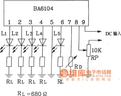
BA6104--the 5 bit LED potentiometer drive integrated basic application circuitAs the BA6104 input stage is in the PNP compound transistor basic pole input way, so its input impedance is very high. The output stage is emitter follower, so by adjusting the LED external resistor RL in the figure, the LED drive circuit can be changed. The external resistor, which is connected with 7-pin, can change Vref, when 7-pin is released, the Vref is controlled by IC, and its value is close to 1V. If the LED display LEV is required to be lower than 1v, we just link a resistor RD between 7-pin and the ground, then the Vref is reduced, see as the figure. (View)
View full Circuit Diagram | Comments | Reading(1218)
TA8170--the stereo decoding integrated circuit
Published:2011/6/9 22:36:00 Author:qqtang | Keyword: stereo decoding, integrated circuit
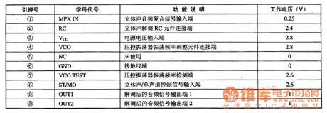
TA8170 is the stereo decoding integrated circuit produced by Toshiba, which is widely used in low-voltage radio circuit as the demodulator of modulate stereo signals, such as walkman and car stereo, etc.1.function featuresTA8170 contains the voltage control oscillator, stereo sound decoing circuit, mixing signal pre-amplifier circuit, stereo/single channel shifting control circuit and other affiliated circuits.2. Pin functions and dataTA8170 is in 10-pin single line package, whose pin functions and data are listed in table 1.
(View)
View full Circuit Diagram | Comments | Reading(632)
| Pages:1793/2234 At 2017811782178317841785178617871788178917901791179217931794179517961797179817991800Under 20 |
Circuit Categories
power supply circuit
Amplifier Circuit
Basic Circuit
LED and Light Circuit
Sensor Circuit
Signal Processing
Electrical Equipment Circuit
Control Circuit
Remote Control Circuit
A/D-D/A Converter Circuit
Audio Circuit
Measuring and Test Circuit
Communication Circuit
Computer-Related Circuit
555 Circuit
Automotive Circuit
Repairing Circuit