
Circuit Diagram
Index 1781
The electronic birds repeller circuit diagram 3
Published:2011/6/10 11:22:00 Author:Lucas | Keyword: electronic, birds repeller
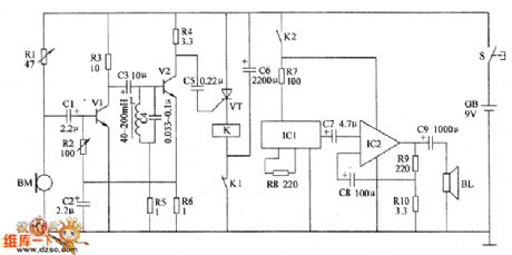
The electronic birds repeller circuit is composed of the pickup amplifier circuit, selective frequency amplifier circuit, trigger circuit, sound effect circuit and the audio amplifier circuit, and the circuit is shown as the chart. Pickup amplifier circuit consists of the microphone BM, preamp amplifier tube V1, resistors R1 ~ R3 and capacitors C1, C2. Selective frequency amplifier circuit is composed of the capacitors C3, C4, inductor L, resistors R4 ~ R6 and amplification tube V2. Trigger circuit is composed of the capacitors C5, C6, thyristor VT, relay Κ. Sound effect circuit is composed of the integrated circuit IC1 and resistor R8. Audio amplifier circuit is composed of the integrated circuit IC2, resistors R9, R1O, capacitors C8, C9 and speaker BL. RI and R2 use the sealed resistors; R3 ~ R1O choose 1/4W carbon film resistors. C1 ~ C3 and C6 ~ C9 choose aluminum electrolytic capacitors with the voltage in 16V.
(View)
View full Circuit Diagram | Comments | Reading(2432)
Electronic birds repeller circuit diagram 3
Published:2011/6/10 10:52:00 Author:Lucas | Keyword: Electronic, birds repeller

The electronic birds repeller circuit is composed of the solar charging circuit, light control electronic switch circuit, oscillator A, oscillator B, sound generator, audio amplifier output circuit and motor control circuit, and the circuit is shown as the chart. Solar charging circuit is composed of the solar cell GBI, isolation diode VD1 and the battery GB2. Light control electronic switch circuit consists of the light sensitive resistor RC and the electronic switch IC IC1. Oscillator A consists of the resistor R1, potentiometers RP1, RP2, diodes VD2, VD3, capacitors C1, C2, and time-based integrated circuit IC2. Sound generator circuit consists of resistors R2, R3, Zener diode VS and audio integrated circuit IC3. Audio amplifier output circuit is composed of the capacitors C3 ~ C5, audio power amplifier integrated circuit IC4 and speaker BL. Oscillator B consists of the resistors R4, R5, capacitors C6, C7, and time-based integrated circuit IC5.
(View)
View full Circuit Diagram | Comments | Reading(5616)
Electronic pests repeller circuit diagram 2
Published:2011/6/10 11:11:00 Author:Lucas | Keyword: Electronic , pests repeller
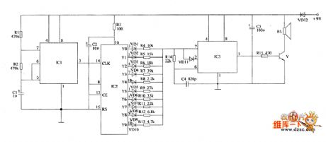
The electronic insect circuit is composed of the clock oscillator, counter, multivibrator and the audio output circuit, and the circuit is shown as the chart. The clock oscillator consists of the time-base IC IC1 and related peripheral components. The circuit can generate 1Hz clock signal, which is output form the pin 3 of IC1 and directly added to the pin 14 of IC2 (CLK). Multivibrator IC3 consists of the time-base IC IC3 and related peripheral components. It is used to produce 23 ~ 64kHz ultrasonic signals. Counter is composed of the integrated circuit IC2, diodes VD1 ~ VD10 and many RC components. All resistors use 1/4W carbon film resistors. C1 ~ C3 select the aluminium electrolytic capacitor with the withstand voltage being 16V; C4 uses ceramic capacitors. VD1 ~ VD11 select 1N4148 switching diodes; VD12 uses 1N4007 rectifier diode. IC1 and IC3 choose NE555 time-base integrated circuits.
(View)
View full Circuit Diagram | Comments | Reading(2469)
Pressure regulation and timing amphibious controller circuit
Published:2011/5/19 1:01:00 Author:TaoXi | Keyword: Pressure regulation, timing, amphibious controller
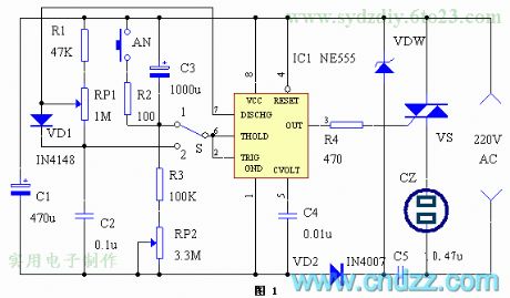
When the pressure regulation, timing selecting switch S2 is at the position 1, the timing control circuit is composed of the NE555, S, C3, RP2 and VS.etc. When using, you press AN, C3 will rapidly discharge through R2 and AN, at this time, pin-2 and pin-6 of the NE555 has the high level voltage, pin-3 outputs the low level voltage, the bidirectional thyristor VS conducts and the output socket CZ outputs the voltage. The DC current charges C3 through RP2 and R3, after C3 is fully charged, the voltage of NE555's pin-2 and pin-6 reduces to 1/3 of the dc power supply voltage. At this time, the NE555 resets and the pin-3 outputs the high level voltage, VS cuts off, CZ has no output voltage. (View)
View full Circuit Diagram | Comments | Reading(826)
Electronic pests killing lamp circuit diagram 1
Published:2011/6/10 10:06:00 Author:Lucas | Keyword: Electronic , pests killing lamp
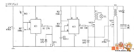
The electronic pests killing lamp circuit consists of the light control switch circuit, multivibrator, black light lamp drive circuit and high-voltage generator circuit, and the circuit is shown as the chart. Light control switch circuit consists of the photosensitive resistor RC, time-base integrated circuit IC1, potentiometer RP, resistor R1, Zener diode VS1 and field-effect transistor VF1. Multivibrator is composed of the time-base integrated circuit IC2, resistors R2, R3 and capacitor C2. Black light driver circuit consists of the resistor M, voltage regulator diode VS2, field-effect transistor YF2, pulse transformer T1 and black light EL. High-voltage generator circuit consists of the R4, VS2, and field-effect transistors VF3, high-voltage rectifier diode VD, and step-up transformer T2.
(View)
View full Circuit Diagram | Comments | Reading(1165)
555 dream color light control circuit
Published:2011/5/21 21:59:00 Author:TaoXi | Keyword: dream, color light, control circuit
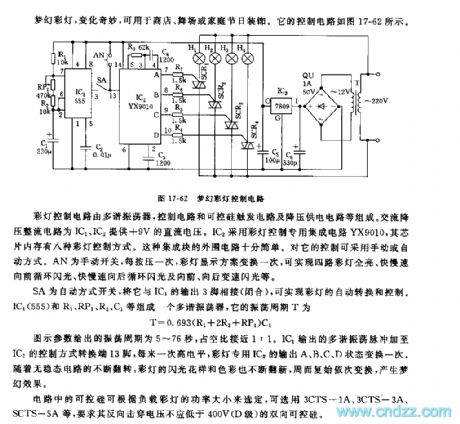
The color light control circuit is composed of the multivibrator, the control circuit, the SCR trigger circuit and the step-down power supply circuit. The AC step-down rectifier circuit uses the +9V DC voltage which is supplied by IC1 and IC2. IC2 uses the color light control application-specific integrated circuit YX9010, the chip memory has eight kinds of color light control mode. AN is the hand switch, every time you press it, the color light display solution will change, and this circuit can turn on all the four channels of color lights.
(View)
View full Circuit Diagram | Comments | Reading(538)
Electronic pests killing lamp circuit diagram 2
Published:2011/6/10 10:32:00 Author:Lucas | Keyword: Electronic , pests killing lamp
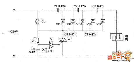
The electronic pests killing lamp circuit consists of the light control switch circuit and voltage doubling rectifier circuit, and the circuit is shown as the chart. Light control switch circuit is composed of the photoresistor RC, capacitor CO, lamp EL, resistor R, bidirectional trigger diode V and thyristor VT. Doubler rectifier circuit consists of the capacitors C1 ~ C5 and rectifier diodes VD1 ~ VD5. R uses 1W metal film resistor; RG uses the MOL series of photosensitive resistor, and the light resistance should be less than or equal to 3KΩ and dark resistance be greater than or equal to 5MΩ. CO selects polyester capacitor with the voltage being 160V ; C1 ~ C5 select the high-voltage paper capacitors or CBB capacitors with the voltage being 600V. VD1 ~ VD5 use 1N4007 silicon rectifier diodes. V uses DB3 or 2CTS series of bidirectional trigger diode. VT uses 3CTS3/600V or TCL336A (3A, 600V) bidirectional thyristor. EL chooses 3W white cold cathode lamp.
(View)
View full Circuit Diagram | Comments | Reading(772)
555 sound control delay lighting switch circuit
Published:2011/5/22 0:04:00 Author:TaoXi | Keyword: sound control, delay, lighting switch
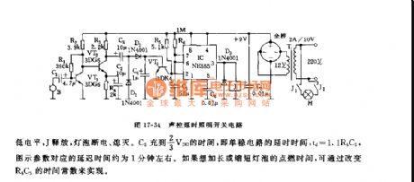
As the figure 17-34 shows, the switch circuit is composed of the audio amplifier circuit, the rectifier circuit, the monostable trigger circuit and the relay control circuit.etc. This circuit can be used in wide range of applications such as the corridors and stairs.
The audio signal which is collected by the pickup is also amplified by the VT1 and VT2, then it is rectified by the D1 and D2 to make the VT3 in the state of saturated conduction, also it makes the voltage of pin-2 less than 1/3VDD, the 555 sets, pin-3 has the high level voltage, the relay closes to turn on the power supply of the floodlight. When the sound is over, VT3 cuts off, C5 is charged through R5, when pin-6's trigger electrical level is more than 2/3VDD, the 555 resets, pin-3 has the low level voltage, J releases and the light turns off.
(View)
View full Circuit Diagram | Comments | Reading(552)
555 sound control turn-off delay switch circuit
Published:2011/5/22 2:47:00 Author:TaoXi | Keyword: sound control, turn-off, delay switch
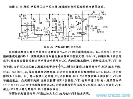
The capacitance step-down rectifier circuit supplies the VDD=6V DC power supply voltage to the sound control circuit. IC1 uses the special sound control integrated circuit SK-1, and this integrated circuit has the bi-stable flip-flop and the 3-stage amplifier. In peacetime, the pin-9 of IC1 has the low electrical level, but when the pick-up B receives the sound signal of clap, the bi-stable of IC1 flips, pin-9 has the high level voltage, VT1 conducts. Because pin-2 of IC2(555)'s trigger level is less than 1/3VDD, so 555 sets, pin-3 has the high level voltage, the light turns on.
(View)
View full Circuit Diagram | Comments | Reading(957)
555 electronic candle circuit
Published:2011/5/24 2:52:00 Author:TaoXi | Keyword: electronic candle
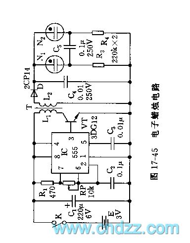
As the figure 17-45 shows, the electronic candle circuit is composed of the 555 oscillator and the boosting circuit.etc.
The astable multivibrator is composed of the 555 and R1,RP,C2.etc, the oscillation frequency f=1.44/(R1+RP)C2, by adjusting RP, you can make the oscillation frequency to 1kHz. The 555's output port drives the VT boosting amplifier circuit, the secondary stage of the transformer T can produce the 100V 1kHz singal, and this signal is rectified by the diode, then adds to the load neon tube to produce the soft and bright light. The transformer T uses the M4 type magnetic core.
(View)
View full Circuit Diagram | Comments | Reading(1757)
555 electronic christmas tree circuit
Published:2011/5/22 3:33:00 Author:TaoXi | Keyword: electronic, christmas tree
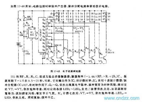
As the figure 17-48 shows, this circuit is composed of the clock pulse generator, the pulse distributor circuit and the driving display circuit.
The astable multivibrator is composed of the 555 and RP1,R1,R2,C1, the oscillation frequency f=1.44/(RP1+R1+2R2)C1. The oscillation period T=1/f. It's output is uses as the counting clock of IC2, IC2 uses the decimal counter/pulse distributor CC4017, under the action of the clock, Q0 ~ Q9 appeare the high-level pulses one by one, the pulse width is the clock period, and the pulses conduct the corresponding VT1 - VT6 in one time.
(View)
View full Circuit Diagram | Comments | Reading(959)
555 electronic festival candle circuit
Published:2011/5/22 4:07:00 Author:TaoXi | Keyword: electronic, festival candle
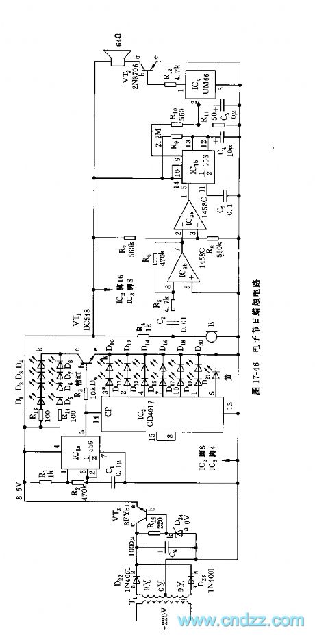
As the figure 17-46 shows, the electronic festival candle circuit is composed of the step-down voltage stabilizer, the candle light display circuit and the music blessing circuit.etc. The candle light display circuit is composed of the clock generator, the annular counter and the 21 LEDs which are used as the flame.
The astable multivibrator is composed of the dual time base circuit IC1a(1/2 556) and the R1,R2,C1, the oscillation frequency f=1.44/(R1+2R2)C1.
The parameters of the figure has the oscillation frequency of 20Hz. It's pin-5 is used as the shift clock CP in the IC2 annular counter. The IC2(CD4017) is one piece of decimal count / pulse distributor, it's R port and pin-13 connect to the ground to form the annular count circuit.
(View)
View full Circuit Diagram | Comments | Reading(856)
555 advertisement decoration light controller circuit
Published:2011/5/22 7:19:00 Author:TaoXi | Keyword: advertisement, decoration light, controller circuit
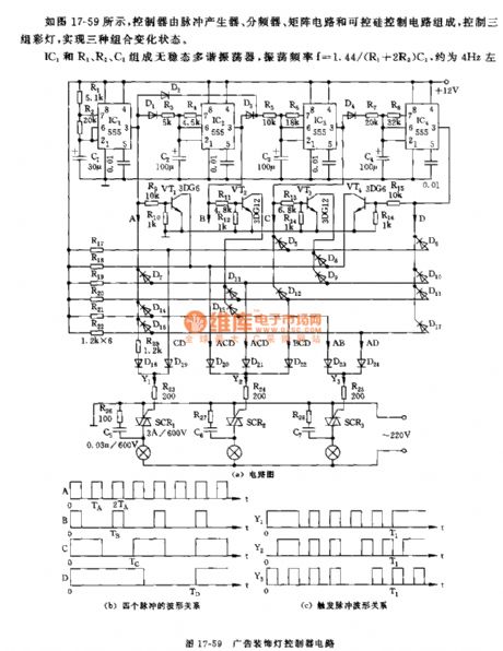
As the figure 17-59 shows, the controller is composed of the pulse generator, the frequency divider, the matrix circuit and the SCR control circuit. We can achieve three kinds of combination change state by controlling the three groups of color lights.
The astable multivibrator is composed of the IC1 and R1,R2,C1, the oscillation frequency f=1.44/(R1+2R2)C1, it is about 4Hz. The trigger which is composed of the IC2 and R3,R4,C2 outputs the square-wave A's half wave to the IC1, as the B of figure (b) shows.
The waveform relationship between Y1,Y2 and Y3 is as shown in figure (c). By changing the logical combinations of the matrix, we can get more change forms.
(View)
View full Circuit Diagram | Comments | Reading(1025)
555 guest welcome and farewell electronic model circuit
Published:2011/6/7 8:26:00 Author:TaoXi | Keyword: 555, guest, welcome, farewell, electronic model
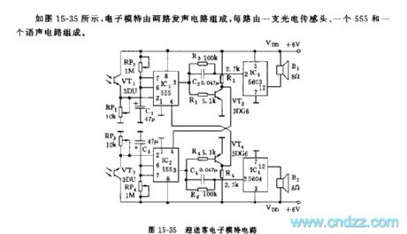
As the figure 15-35 shows, the electronic model is composed of two channels of generating circuit, each channel of circuit is composed of a photoelectric sensor, a 555 and a voice circuit.
The photoelectric sensor uses the 3DU type photosensitive tube, when the guest comes in or goes out, guest's body interrupts the light which illuminates on the VT1(or VT3), so the photosensitive tube has the high resistance, the pin-2's electric potential of 555 is lower than the 1/3VDD trigger electrical level, so the IC1 (or IC2) sets to output the high electrical level, the IC3 is triggered to send out the voice of welcome . At the same time the VT2 conducts, the collector electrode's low electric potential adds to the pin-4 of IC2 to mandatory reset the 555 no matter whether the VT3 has illumination.
(View)
View full Circuit Diagram | Comments | Reading(649)
555 baby wave bed automatic sloshing circuit
Published:2011/6/7 8:39:00 Author:TaoXi | Keyword: 555, baby wave bed, automatic, sloshing
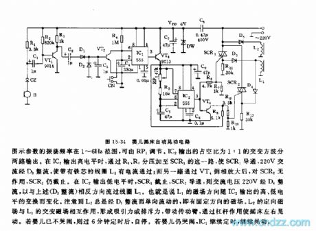
As the figure 15-34 shows, the circuit is composed of the pickup, the timer, the oscillator and the drive device, it can be used to automaticly shake the bed when the baby is crying.
The pickup B changes the baby cry into the electrical signal, and this signal is amplified and rectified by VT1 to conduct the VT2, C4 discharges and IC1(555) sets, pin-3 has the high electrical level, the timing begins. The timing time td=1.1R4C4, the figure parameters' timing time is about 6 minutes. In the timing time, VT3 conducts and the IC2 multivibrator gets power to work, the oscillation frequency f=1.44/(RP1+R5)C5, the figure parameters' oscillation frequency is in the range of 1 to 6Hz, and the oscillation frequency can be adjusted by RP1. The duty ratio of IC2 is 1:1.
(View)
View full Circuit Diagram | Comments | Reading(871)
555 remote control doorbell circuit
Published:2011/6/7 8:53:00 Author:TaoXi | Keyword: 555, remote control, doorbell

As the figure 15-23 shows, the circuit is composed of a launcher and a receiver.The launcher is composed of the self-excited multivibrator (composed of the VT1, VT2, L2, C3.etc) and the coupling coil L1, the oscillation frequency is between 30 to 40MHz.
The receiver is composed of the antenna, the tuning coil, the times voltage detector, the monostable timing circuit and the sound circuit. The monostable trigger circuit is composed of the 555 and the RP2, C9, when it receives the high-frequency signal, the signal is selected, detected, amplified by the circuit to trigger the IC1, the 555 sets, pin-3 has the high potential as the power supply of the IC2, so IC2 sends out the music. The length of the music depends on the monostable temporarily stabel timing time, the figure parameters' timing time t=1.1RP2C9 (about 1 to 10 seconds), and it is adjusted by RP2.
(View)
View full Circuit Diagram | Comments | Reading(891)
Electronic detonating device circuit diagram 2
Published:2011/6/9 5:45:00 Author:Lucas | Keyword: Electronic, detonating device
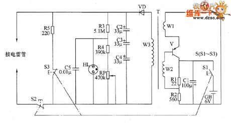
The electronic circuit is composed of the oscillator, booster circuit, charging instruction circuit and discharging circuit, and the circuit is shown as the chart. Oscillator circuit consists of transistor V, capacitor C1, resistor R1, R2, electric battery CB, charging switch S1 and the windings W1, W2 of step-up transformer T. The windings w3 of step-up transformer T, rectifier diode VD and capacitors C2 ~ C4. Charging instruction circuit consists of resistors R3, R4, potentiometer RP, capacitor C5 and neon light HL. Discharging circuit is composed of the discharging switch S2, discharging switch S3 and resistor R5. S1 ~ S3 is the three groups of control contacts of initiation button. R1 and R2 select 1/2W metal film resistors.
(View)
View full Circuit Diagram | Comments | Reading(664)
Electronic detonating device circuit diagram 1
Published:2011/6/9 5:37:00 Author:Lucas | Keyword: Electronic , detonating device
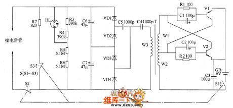
The electronic circuit is composed of the self-excited oscillator, high voltage generating circuit, charging instruction circuit and discharging circuit, and the circuit is shown as the chart. The self-excited oscillator circuit consists of resistors R1, R2, capacitors C1 ~ C3, transistors V1, V2, charging switch S1, battery CB, and the windings W1, W2 of step-up transformer T. The high-voltage generating circuit is composed of the winding W3 of step-up transformer T, capacitors C4 ~ C7 and rectifier diodes VD1 ~ VD4. C4, C5, and VD1 ~ VD4 form the doubler rectifier circuit. Charging instruction circuit consists of resistors R3 ~ R6 and neon light HL. Discharging circuit is composed of the discharging switch S2, bleed resistor R7 and bleed switch S3.
(View)
View full Circuit Diagram | Comments | Reading(611)
LED dynamic display sequence generator circuit
Published:2011/6/7 19:13:00 Author:TaoXi | Keyword: LED, dynamic, display, sequence generator
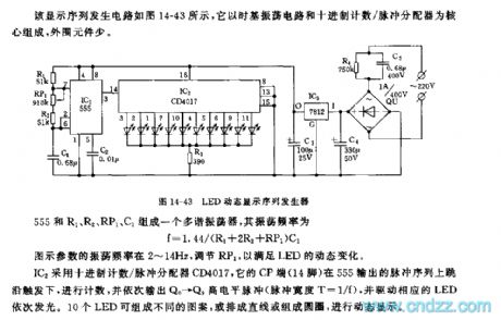
The LED dynamic display sequence generator circuit is as shown in the figure 14-43, it is composed of the time-base oscillating circuit and the decimal count/pulse distributor, and it has a few of external components.
The multivibrator is composed of the 555 and R1, R2, RP1, C1, the oscillation frequency f=1.44/(R1+2R2+RP1)C1. The figure parameters' oscillation frequency is in the range of 2~14Hz, you can adjust RP1 to meet the dynamic changes of LED.
The IC2 uses the decimal count/pulse distributor CD4017, it's CP port (pin-14) is triggered by the pulse sequence jump on edge to count, and it outputs the Q0~Q9 high-level pulses in proper sequence (pulse width T=1/f), also it drives the corresponding LEDs to turn on in proper sequence.
(View)
View full Circuit Diagram | Comments | Reading(1003)
555 distance remote control amplifier switch circuit
Published:2011/6/7 19:27:00 Author:TaoXi | Keyword: 555, distance, remote control, amplifier, switch
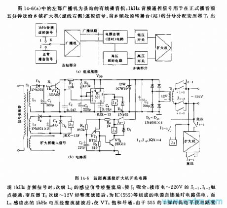
When the rebroadcasting station's distribution transformer T1 outputs the 1kHz audio signal, the subprime stage L2's sensing signal is rectified by the circuit to make J1 to close, the contact points J1-1 and J1-2 which are connected with the city electricity turn on, the transformer T2's subprime stage is rectified and filtered by the circuit to supply power to the power self-locking delay circuit which is composed of the IC(555).etc.
In the power self-locking delay circuit, the charging time of the IC(555) monostable circuit is td=1.1R3C3, it is about 2 minutes, this means in the intermittent time (less than 2 minutes), the 555 will not stop because of the monostable delay effect. After the announcing, T1 has no input signal, J releases, and after 2 minutes the J2 releases too, the power self-locking circuit cuts off.
(View)
View full Circuit Diagram | Comments | Reading(843)
| Pages:1781/2234 At 2017811782178317841785178617871788178917901791179217931794179517961797179817991800Under 20 |
Circuit Categories
power supply circuit
Amplifier Circuit
Basic Circuit
LED and Light Circuit
Sensor Circuit
Signal Processing
Electrical Equipment Circuit
Control Circuit
Remote Control Circuit
A/D-D/A Converter Circuit
Audio Circuit
Measuring and Test Circuit
Communication Circuit
Computer-Related Circuit
555 Circuit
Automotive Circuit
Repairing Circuit