
Circuit Diagram
Index 1780
555 alarm, doorbell and lighting controller circuit
Published:2011/5/30 10:11:00 Author:TaoXi | Keyword: 555, alarm, doorbell, lighting, controller
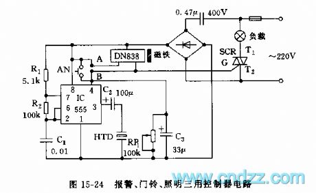
As the figure 15-24 shows, the controller circuit is composed of the switch type Hall integrated circuit DN838 and the astable multivibrator (composed of the 555), this circuit can be used in wide range of applications such as the automatic door opening, automatic delay alarm, automatically turns off the lights and also it can be used as the doorbell.
The astable multivibrator is composed of the IC(555) and R1,R2,C1, the oscillation frequency f=1.44/(R1+2R2)C1, it is about 1000Hz. The reset switch and the SCR trigger switch are composed of the DN838 and the small magnets. When the DN838 loses the magnetism, poins A and B conduct, SCR is trigger conduction, the light turns on, the 555 starts working, the piezoelectric ceramic HTD sends out the alarm. When you close the door, the DN838 receives the magnetism, points A and B cut off, the SCR cuts off too, the light turns off.
(View)
View full Circuit Diagram | Comments | Reading(2226)
Static electricity eliminator circuit diagram 2
Published:2011/6/9 4:08:00 Author:Lucas | Keyword: Static electricity eliminator
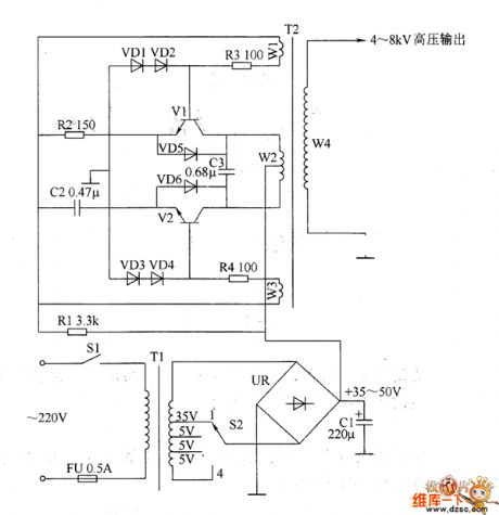
The static electricity eliminator circuit is composed of the power circuit and oscillation step-up circuit, and the circuit is shown as the chart. Power circuit consists of the power switch S1, fuse FU, power transformer T1, bridge rectifier UR, filter capacitor C1 and voltage selecting switch S2. Oscillation step-up circuit consists of the resistors R1 ~ R4, capacitors C2 and C3, diodes VD1 ~ VD6, step-up transformer T2 and transistors VI, V2. R1 selects lW metal film resistor; R2 ~ R4 select 1/4W metal film resistors. C1 uses aluminium electrolytic capacitor with the voltage in 63V: C2 and C3 select the CBB capacitors with the voltage in 250V. VD1 ~ VD4 use 1N4007 silicon rectifier diodes; VD5 and VD6 use 1N5406 silicon rectifier diodes.
(View)
View full Circuit Diagram | Comments | Reading(2567)
555 20-channel responder circuit
Published:2011/5/30 19:09:00 Author:TaoXi | Keyword: 20-channel, 555, responder
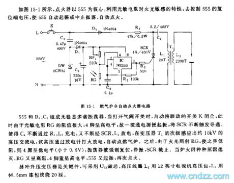
The astable multivibrator is composed of the 555 and R2,C3. When you open the valve switch, this circuit will automatically close the linkage switch K, at this time the photoresistor RG has high resistance, pin-4 has the high electrical level, so if the power supply is connected, the circuit will start working Immediately to trigger and conduct the SCR, so C4 is continuously charged through R1 and R2, then is continuously discharged through SCR and L1, the secondary stage of the transformer T1 will produce the 10kV HVAC, this HVAC is discharged through the electrodes to automaticly light the gas furnace. Then because of the firelight illuminates RG, RG has the low resistance, so pin-4 has the low electrical level (lower than 0.6V), the SCR cuts off.
(View)
View full Circuit Diagram | Comments | Reading(572)
Welder no-load power saver circuit diagarm 8
Published:2011/6/10 5:41:00 Author:Lucas | Keyword: Welder, no-load , power saver
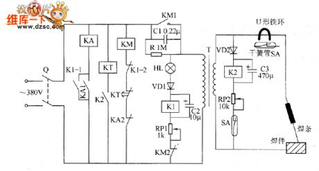
The welder no-load power saver circuit is composed of the knife switch Q, relays K1 and K2, relay KA, AC contactor KM, time relay KT, reed SA, diodes VD1 and VD2, LED HL, resistor R, capacitors C1 ~ C3, potentiometers RP1 and RP2 and the welding transformer T, and the circuit is shown as the chart. R uses 1/4W metal film resistor. RP1 and RP2 use 2W wire-wound resistors. C1 uses the CBB capacitor with the voltage being 630V; C2 uses the aluminium electrolytic capacitor with the voltage being 50V; C3 uses the aluminium electrolytic capacitor with the voltage being 16V. VD1 and VD2 use 1N4007 silicon rectifier diodes. KA uses the intermediate relay with the coil voltage selection 380V (or 220V) AC.
(View)
View full Circuit Diagram | Comments | Reading(1394)
Welder no-load power saver circuit diagarm 7
Published:2011/6/10 5:35:00 Author:Lucas | Keyword: Welder , no-load , power saver
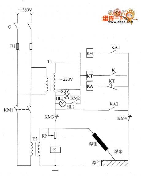
The welder no-load power saver circuit is composed of the power transformer T1, intermediate relay KA, relay K, time relay KT, AC contactor KM, potentiometer RP and indicator lights H12, HL1, and the circuit is shown as the chart. Knife switch Q, fuse FU, welder transformer T2 form the main circuit of original welder. RP uses 2W wire-wound resistor. HL1 and HL2 select 1W, 6.3V lights. KA chooses the intermediate relay with the contact current capacity being greater than 5A, coil voltage being 220V AC. KT selects the time relay with the coil voltage being 220V AC, such as the JS11 series. KM uses 220V AC coil voltage contactor. Q, FU, and KM's contact current capacity should be based on reasonable selection of real power.
(View)
View full Circuit Diagram | Comments | Reading(988)
555 discoloration electronic brooch circuit
Published:2011/5/30 20:52:00 Author:TaoXi | Keyword: 555, discoloration, electronic, brooch

This electronic brooch circuit uses the double time base integrated circuit 556 as the core. It changes the color automaticly and has a lots of colours. The circuit is as shown in figure 15-47.
The astable multivibrator is composed of the IC1-a(1/2 556) and R1,R2,C1, the oscillation frequency fc=1.44/(R1+2R2)C1, it is about 1Hz.
The multivibrator is composed of the IC1-b(1/2 556) and R4,R5,C4, the oscillation frequency is the same as the IC1-a's oscillation frequency, the difference between the them is only 0.0027Hz.
When IC1-a outputs the high electrical level, the LED1 issues the red light; if the IC1-b outputs the low electrical level, LED2 turns off, the whole glowing tube shows the red color.
(View)
View full Circuit Diagram | Comments | Reading(572)
Welder no-load power saver circuit diagarm 6
Published:2011/6/10 5:07:00 Author:Lucas | Keyword: Welder , no-load , power saver
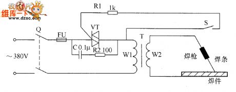
The welder no-load power saver circuit is composed of the knife switch Q, fuse FU, capacitor C, resistors R1 and R2, thyristor VT, welding transformer T and the trigger switch S, and the circuit is shown as the chart. Q, FU, VT, and T form the main circuit of the welder, and S, R1, and VT form the power saving switching circuit; C and R2 form the current limiting circuit. Before the the trigger switch S being connected, VT is in the off state. R1 selects 1/2W metal film resistor; R2 uses 1OW cement resistor. C selects the CBB capacitor with the voltage being 400V. VT uses 30 ~ 50A, 600V directional triode thyristor. S uses the micro switch or small normally open button. The choices of FU and Q should be based on the actual power of T.
(View)
View full Circuit Diagram | Comments | Reading(1646)
Welder no-load power saver circuit diagarm 5
Published:2011/6/10 4:58:00 Author:Lucas | Keyword: Welder, no-load , power saver
The welder no-load power saver circuit is composed of the current detection control circuit and power saving control circuit, and the circuit is shown as the chart. Current detection control circuit is composed of the current transformer TA, bridge rectifier UR, resistor R1, Zener diode VS, capacitor C2 and diode VD. Power control circuit consists of resistor R2, capacitor C1 and thyristor VT. R1 uses 3W wirewound resistor; R2 uses 2W metal film resistor. C1 uses the CBB capacitor or oil capacitor with the voltage being 630V; C2 uses the aluminium electrolytic capacitor with the voltage being 16V. VD selects 1N4007 silicon rectifier diode. VS selects 2CW12 silicon voltage regulator diode. UR selects 1A, 50V bridge rectifier.
(View)
View full Circuit Diagram | Comments | Reading(3694)
Welder no-load power saver circuit diagarm 4
Published:2011/6/10 4:22:00 Author:Lucas | Keyword: Welder, no-load , power saver
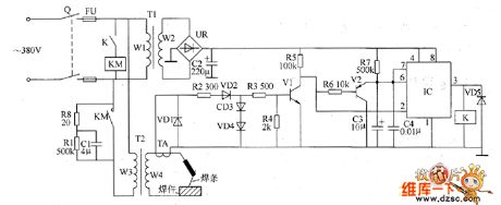
The welder no-load power saver circuit is composed of the +12 V power supply circuit, current detection control circuit, delay control circuit and the control implementation circuit, and the circuit is shown as the chart. +12 V power supply circuit is composed of the knife switch Q, fuse FU, power transformer T1, bridge rectifier UR and filter capacitor C2. Current detection control circuit is composed of the current transformer TA, diodes VD1 ~ VD4, resistors R2 ~ R6, transistors V1 and V2. Delay control circuit is composed of the resistor R7 and capacitors C3, C4, the time-base integrated circuit IC, relay K, AC contactor KM and diode VD5. R1, R3 ~ R7 select 1/4W metal film resistors; R2 uses 2W metal film resistor.
(View)
View full Circuit Diagram | Comments | Reading(798)
555 voltage adjustment and timing multi-function electric outlet circuit
Published:2011/5/30 21:21:00 Author:TaoXi | Keyword: 555, voltage adjustment, timing, multi-function, electric outlet
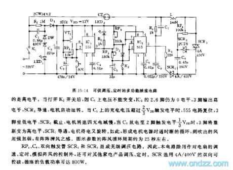
As the figure 15-14 shows, the circuit is composed of the step-down rectifying power supply, the steplessly voltage regulating circuit, the natural wind artificial circuit and the timing circuit.etc.
The timing circuit is composed of the IC1(555), the MOSFET VT1, RP1 and C3.etc. If you open the power supply switch K1 and press AN, pin-2 has the ground electric potential, IC1's output high electric potential adds to the pin-4 of IC2(555). IC2 is the fan speed controller or natural wind artificial control circuit. After you open the timing switch K2, pin-3 of IC1 still has the high electric potential. Then C3 is charged through the VT1's power supply port, when C3's voltage is higher than pin-6's threshold level 2/3VDD, 555 flips and outputs the low electric potential.
(View)
View full Circuit Diagram | Comments | Reading(629)
Welder no-load power saver circuit diagarm 3
Published:2011/6/10 6:06:00 Author:Lucas | Keyword: Welder, no-load , power saver

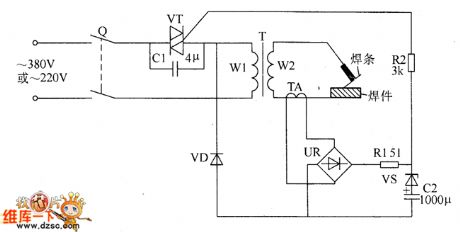
The welder no-load power saver circuit is composed of the power supply circuit, delay trigger circuit and the control implementation circuit, and the circuit is shown as the chart. Power supply circuit is composed of the knife switch Q, fuse FU, the normally open contact of AC contactor KM, welding transformer T, rectifier diode VD1, filter capacitor C2, Zener diode VS1 and current limiting resistor R1. The delay trigger circuit consists of Zener diodes VS2 and VS3, potentiometer RP, resistors R2 ~ R5, capacitor C3, diode VD2 and single-junction transistor VU. The control implementation circuit is composed of the relay K, diode VD3, thyristor VT, AC contactor KM and capacitor C1. R1 uses 1/2W metal film resistor; R2 ~ R5 select 1/4W metal film resistors.
(View)
View full Circuit Diagram | Comments | Reading(916)
Welder no-load power saver circuit diagarm 1
Published:2011/6/10 5:52:00 Author:Lucas | Keyword: Welder, no-load , power saver
The welder no-load power saver circuit is composed of the relay drive circuit, low-voltage detection control circuit, high voltage time control circuit or voltage adaptive tracking regulation circuit, and the circuit is shown as the chart. The voltage adaptive tracking regulation circuit is composed of the voltage-regulator diode VS3, resistor R3 and transistors V3, V4. Relay driver circuit is composed of the relay K, transistors V1, V2 and diode VD3 and other components. KM is the AC contact, and C is the buck capacitor, K1 is the Κ normally open contact of the relay K, VD1 is the rectifier diode, C1 is the filter capacitor. R1 ~ R12 select 1W metal film resistors. C chooses non-polar condenser with the withstang voltage being 630V; C1 selects the aluminium electrolytic capacitor with the voltage being 250V.
(View)
View full Circuit Diagram | Comments | Reading(800)
555 hotel security electronic lock device circuit
Published:2011/5/30 21:43:00 Author:TaoXi | Keyword: 555, hotel, security, electronic lock
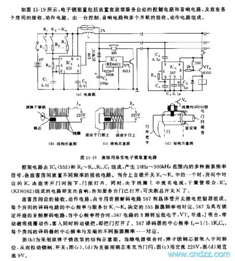
The control circuit is composed of the IC1(555) and the R1~Rn,R0,C1, it produces many kinds of oscillation frequency signals in the range of 10Hz~500kHz, you install the receiving circuits which have different frequencies. When you close one of the self-locking switches K1~Kn, and the passenger presses the corresponding Kn, the door opens.
The receiving action circuit in the guest room is composed of the special audio decoder circuit 567 and the transistor switch relay controller.
Figure (b) shows the structure schematic of the original night lock. When the relay closes, the steel core of the night lock is sucked in the middle part to pull the lock handle and switch.
(View)
View full Circuit Diagram | Comments | Reading(1009)
555 household appliances protector circuit
Published:2011/6/2 18:59:00 Author:TaoXi | Keyword: 555, household appliances, protector
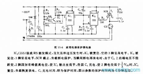
As the figure 15-6 shows, the household appliances protector is composed of the step-down rectifier circuit, the under-voltage over-voltage sampling circuit and the monostable delay circuit.etc.
The IC1(555) is in the RS trigger mode, when it is under-voltage or over-voltage, IC1 is set, so pin-3 has the low electrical level, SCR cuts off, the load is out of power. When the power is coming, the terminal voltage of C4 can not be abrupt-change, and pin-2 has the high potential peak to make the IC2 to output the low electrical level, when the C4 is charged until pin-2's electrical level is lower than 1/3VDD, IC2 sets, the load restores the power supply.
(View)
View full Circuit Diagram | Comments | Reading(756)
555 household earthquake sound and light alarm circuit
Published:2011/6/2 19:10:00 Author:TaoXi | Keyword: 555, household, earthquake, sound, light, alarm circuit
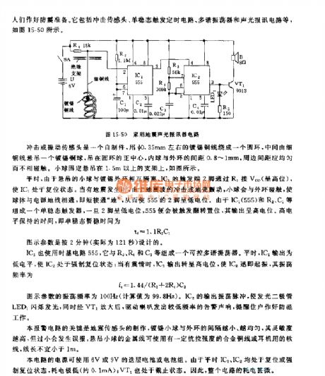
This circuit is composed of the impact sensor, the monostable trigger timing circuit, the multivibrator and the sound & light alarm circuit.etc, as the figure 15-50 shows.
The IC2 uses the time base circuit 555, the controllable multivibrator is composed of the IC2, R3, R4 and C3.etc, in peacetime the IC1 outputs the low electrical level to make the IC2 in the mandatory reset state; when the earthquake happens, the IC1 outputs the high electrical level to make the IC2 to start working, the oscillation frequency fc=1.44/(R3+2R4)C3.
The oscillation frequency of the figure parameters are 100Hz. IC2's output oscillation pulse makes the light-emitting diode LED1 to light, at the same time the pulse is amplified by VT1 to drive the speaker to send out the low-frequency alarm sound.
(View)
View full Circuit Diagram | Comments | Reading(932)
Electronic pests killing lamp circuit diagram 5
Published:2011/6/10 6:51:00 Author:Lucas | Keyword: Electronic , pests killing lamp
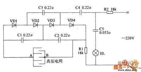
The electronic pests killing lamp circuit consists of high voltage generator circuit and lighting circuit, and the circuit is shown as the chart. Lighting circuit is composed of the resistor R2, capacitor C5 and trap lamp EL. High voltage generator is composed of the resistor R1, capacitors C1 ~ C4, diodes VD1 ~ VD4 and the high voltage grid ( the high voltage electrodes A, B ). One way of the AC 220V voltage limited and bucked by R2, C5 and added on the both ends of EL will make the light turn on; another way limited and bucked by R1, R2 and C1 ~ C4, 4 times voltage doubled and rectified by VD1 ~ VD4 will generate the DC high pressure voltage, which is added to the high voltage electrodes A, B and when the pests flies to EL and they would be killed by the DC high voltage. R1 and R2 select 2W metal film resistors. VD1 ~ VD4 use 1N4007 silicon rectifier diodes.
(View)
View full Circuit Diagram | Comments | Reading(1123)
555 home appliance automatic opening and closing timing circuit
Published:2011/6/6 8:31:00 Author:TaoXi | Keyword: 555, home appliance, automatic, opening, closing, timing
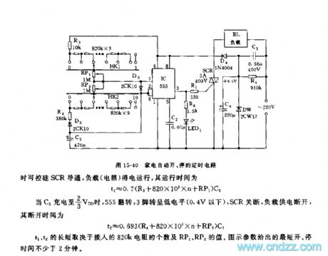
The multivibrator is composed of the 555 and R3,R4,C3. the HK1 and HK2 are the 1X11 single-blade rotary switches, the 820kX9 and RP1, RP2 are connected with them, the 820kX9 and RP1, RP2 can be used in the coarse adjustment and fine adjustment of the oscillation period and the duty ratio. When the 555 outputs the high electrical level, LED1 turns on, at the same time the SCR conducts and the load gets power to work.
When the C3 is charged to 2/3VDD, the 555 everts, pin-3 has the low electrical level (lower than 0.4V), the SCR turns off and the load has no power.
The length of t1, t2 depends on the number of the 820k resistances and the values of RP1 and RP2. The parameters of the figure show the shortest switch time of not less than 2 minutes.
(View)
View full Circuit Diagram | Comments | Reading(696)
Electronic pests killing lamp circuit diagram 4
Published:2011/6/10 6:40:00 Author:Lucas | Keyword: Electronic , pests killing lamp
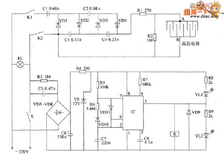
The electronic pests killing lamp circuit consists of the oscillator, control circuit, high voltage generator, LED indicating circuit and power supply circuit, and the circuit is shown as the chart. The oscillator circuit is composed of the time-base integrated circuit IC, resistors R5 ~ R7, diodes VD10, VD11 and capacitors C7, C8. Power supply circuit is composed of the capacitors C5, C6, resistors R3, R4, rectifier diodes VD5 ~ YD8 and voltage regulator diode VS. Control circuit consists of diode VD9, relay K and the pin 3 internal circuit of IC. High-voltage generator circuit consists of the capacitors C1 ~ C4, rectifier diodes VDI ~ VD4, resistors R1, R2, and high-voltage grid (high voltage electrodes A, B). LED indicating circuit consists of the resistors R8, R9, and light-emitting diodes VL1, VL2. R1 and R2 select 2W metal film resistors; R3 and R4 select 1W metal film resistors.
(View)
View full Circuit Diagram | Comments | Reading(1903)
555 home appliance finger touching protector circuit
Published:2011/6/6 8:50:00 Author:TaoXi | Keyword: 555, home appliance, finger touching, protector
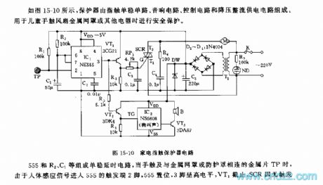
As the figure 15-10 shows, the protector is composed of the finger touching monostable circuit, the music circuit, the control circuit and the step-down rectifier power supply circuit. This device can be used in the applications of children' finger touching fan metal mesh and other electrical equipments' safety protection.
The monostable delay circuit is composed of the 555 and the R2,C1, when the fingers touch with the metal mesh or the sequin TP which is connected with the protective cover, the human sensing signal gets into the 555's trigger port - pin-2, the 555 sets, pin-3 has the high electrical level, VT1 cuts off, the SCR cuts off because there is no trigger current, so the motor M stops. The stop time (the monostable temporary stability time) td=1.1R2C1, the parameter of the figure is about 6 seconds. If the person leaves, the motor will automatic recover operation after 6 seconds.
(View)
View full Circuit Diagram | Comments | Reading(600)
Brood thermostat circuit diagram
Published:2011/6/9 4:49:00 Author:Lucas | Keyword: Brood thermostat
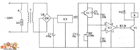
The brood temperature control circuit is composed of the power circuit and temperature detection control circuit, and the circuit is shown as the chart. Power circuit is composed of the power transformer T, bridge rectifier UR, filter capacitors C1, C2, and three-terminal voltage regulator integrated circuit IC1. Temperature detection control circuit is composed of the transistors V1, V2, resistors R1 ~ R3, potentiometer RP, capacitor C3, diode VD, operational amplifier integrated circuit IC2, heater EH and relay Κ. AC 220V voltage bucked by T , rectified by UR, filtered by C1, stabilized by IC1 can provide +6 V power supply for the temperature detection control circuit. R1 ~ R3 select 1/4W carbon film or metal film resistors. C1 and C2 select aluminium electrolytic capacitors with the voltage in 16V.
(View)
View full Circuit Diagram | Comments | Reading(1238)
| Pages:1780/2234 At 2017611762176317641765176617671768176917701771177217731774177517761777177817791780Under 20 |
Circuit Categories
power supply circuit
Amplifier Circuit
Basic Circuit
LED and Light Circuit
Sensor Circuit
Signal Processing
Electrical Equipment Circuit
Control Circuit
Remote Control Circuit
A/D-D/A Converter Circuit
Audio Circuit
Measuring and Test Circuit
Communication Circuit
Computer-Related Circuit
555 Circuit
Automotive Circuit
Repairing Circuit