
Circuit Diagram
Index 1770
The voice recorder circuit
Published:2011/6/9 0:09:00 Author:Seven | Keyword: voice recorder
View full Circuit Diagram | Comments | Reading(1111)
The circuit of air anion generator
Published:2011/6/10 1:09:00 Author:Seven | Keyword: air anion generator
Air anion generatorAir anion generator increases the air anion content by using high voltage electric corona, so that the air is improved and health is promoted, the anions are called air vitamin . The MSc advanced clinical practitioner proves that it can assist to cure the illnesses of respiratory system, circulatory system and nervous system, etc, so it is widely used in the life and medical area.This text is to introduce an effective and open air anion generator, which uses controllable silicon inverted high voltage and suspended discharge needle.
(View)
View full Circuit Diagram | Comments | Reading(745)
The power supply of Jinxing C6458
Published:2011/6/10 1:02:00 Author:Seven | Keyword: power supply, Jinxing
Oscillating process:After being stepped down by R804 and TH803, and then stabilized by ZD801, the 220v AC current becomes a voltage of about 12V, and it is delivered to 16-pin of IC801 by D806 and R806 as the oscillation starting voltage, when the voltage on 16-pin is higher that 10.3v, the circuit starts to oscillate. The 14-pin outputs the motivating pulse which is added to the base electrode by D817,D819~D821, and a 300v DC voltage is imposed on the 1-pin of the switch transformer, the integrated pole of Q801 is connected with 3-pin of the switch transformer, then a AC pulse current is generated between 1-pin and 3-pin. (View)
View full Circuit Diagram | Comments | Reading(557)
Electronic detonating device circuit diagram 3
Published:2011/6/9 5:56:00 Author:Lucas | Keyword: Electronic, detonating device
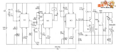
The electronic circuit is composed of the delay switch circuit, insurance switch circuit, timing initiation circuit, charging indicator circuit and detonating power circuit, and the circuit is shown as the chart. The delay switch circuit is composed of time-base integrated circuit IC1, resistors R1, R2, potentiometer RP1, potentiometers C1 ~ C3, diode VD1, thyristor VT1 and the S2-1 contact of detonating switch S2. Insurance switch circuit is composed of the time-base integrated circuit IC2, resistors R3, R4, potentiometer RP2, diodes VD2, VD3, capacitors C4, C5, relay K and S2-2 contacts of S2. The timing initiation circuit is composed of the time-base timer circuit IC IC3, resistors R5, R6, potentiometer RP3, diode VD4, thyristor VT2, capacitors C6 ~ C9 and S2-3 contact of S2. Initiation power circuit consists of transistor V, resistor R7, oscillation step-up transformer T, capacitors C1O ~ C12, thyristor VT2, diodes VD5 with VD6 and S2-4, S2-5 contacts of S2. Charging indicator circuit consists of resistors R8 and neon light HL.
(View)
View full Circuit Diagram | Comments | Reading(668)
The principle circuit of classical Motorola L7 cellphone (1/7)
Published:2011/6/9 0:10:00 Author:Seven | Keyword: principle circuit, Motorola
View full Circuit Diagram | Comments | Reading(771)
The absolutely available switch power supply: Panasonic M12H power supply
Published:2011/6/10 1:05:00 Author:Seven | Keyword: switch power supply, Panasonic
The power supply is used in Panasonic color TV of TC-230H、TC-2030DHN、TC-830D、TC-840D, etc.
Oscillating processThe DC voltage on C836 runs across P1 and P2 coils of T801, and the reaches C pole of the internal switch of IC801 1-pin, in the mean time, it is imposed on B pole of the internal switch of IC801 2-pin by R803, the switch pipe starts to conduct, and the current of E pole runs out from 4-pin of IC801. The current in P1 and P2 coil of T801 is rising and generates sensing signals, the signals are coupled with F2 and F3, at the moment, the sensing voltage polarity of F2 is positive, while F3 is negative. (View)
View full Circuit Diagram | Comments | Reading(740)
The absolutely available switch power supply: Panasonic L15 power supply
Published:2011/6/10 1:07:00 Author:Seven | Keyword: power supply, Panasonic
Oscillating circuitThe DC voltage of 300v on C847 run across the primary coils,P1 and p2, of the energy saver transformer, and then it is imposed on C pole of the internal switch of IC801 3-pin, in the meantime, it is imposed on B pole of the internal switch of IC802 2-pin by R803, so that the switch pipe is conducting. Therefore, the voltage in P1 and P1 coil is coupled with F2 and F3, and the positive feedback is imposed on the 2- and 4-pin(i.e the B- and E-pin of the internal switch pipe) of IC801 by C806 and R804, which makes the switch pipe saturated.
Stabilized circuitThe stabilized circuit is completed in STR50213. (View)
View full Circuit Diagram | Comments | Reading(630)
The absolutely available switch power supply: Sanyo 83P power supply
Published:2011/6/10 1:10:00 Author:Seven | Keyword: switch power supply
Oscillating process:When BG311 is saturated, the current in coils of 4 and 6 is linearly magnified and B301 is saving the field power. The current on E pole of BG311 runs across R330 and generates a linearly magnified sawtooth voltage, the the voltage runs across the 2-pin of A301 by C330 and makes the two control pipes in the 2-pin conducting, after the current on B pole of BG311 is distributed by 3-pin of A301, while the voltage on the negative pole of C330 is also added to the B pole of BG311 by A301 2- and 3-pin, finally, bg311 quits from the saturated state. (View)
View full Circuit Diagram | Comments | Reading(557)
The absolutely available switch power supply: Sanyo 80P power supply
Published:2011/6/10 3:47:00 Author:Seven | Keyword: power supply, Sanyo
Oscillating process:The 300v voltage is imposed on the B pole of switch Q504 by R518 and R519, and Q504 starts to conduct. The 9- and 10-pin of T501 are positive feedback coil, the voltage polarity of 9-pin is positive, while 10-pin is negative. Due to the positive feedback which consists of the B and E pole, R516, R515 and D509, Q504 is saturated quickly.After Q504 is saturated, the current in the primary coil of T501 rises up linearly, the current generates a sawtooth-wave step-down voltage on R514, the voltage is delivered to the B pole of Q502 by R505 and C507, and the sawtooth wave voltage is added on the 6.8V DC voltage of Q502B. (View)
View full Circuit Diagram | Comments | Reading(577)
The absolutely available switch power supply: Hitachi NP8C power supply
Published:2011/6/10 3:47:00 Author:Seven | Keyword: power supply, Hitachi
Oscillating process:The voltage of 300V is imposed on the B pole of pipe Q901 by R911,R907 and R908, then Q901 starts to conduct and the primary coil of T901 begins to have current, in the meantime, a sensing voltage is generated, the polarity of the upper part is positive and the lower part is negative, so that the coil also begins to generate a sensing voltage, and the polarity of upper part is negative and the upper part is positive, the voltage is delivered to B pole of Q901 by R902, R909 and C908, which makes Q901 more conducting, so the positive feedback makes Q901 saturate quickly. During the time of saturating, D906 and D907 are blocked and T901 is saving energy, at the moment, the positive feedback voltage is charging C908 continuously. (View)
View full Circuit Diagram | Comments | Reading(600)
The absolutely available switch power supply: Hitachi NP84C power supply
Published:2011/6/10 1:14:00 Author:Seven | Keyword: power supply, Hitachi
Oscillating process: The DC voltage of about 300V is imposed on the B pole of pipe Q901 by R902, R903 and C905, then Q901 starts to be conducting, then the current on C pole flows through the 1- and 3-pin of the T901 primary coil, a sensing EMF is generated and coupled with the 5- and 10-coil, which generates a sensing voltage that the upper is positive and the lower is negative, the voltage is delivered to B pole of Q901 by R905, C911, R906 and C908, so the current of Q901 is magnified further, the positive feedback makes Q901 saturated and conducting quickly. During the time of saturating, the current in 1- and 3-pin of T901 is rising linearly. (View)
View full Circuit Diagram | Comments | Reading(644)
The absolutely available switch power supply: Hitachi A1PM8C power supply
Published:2011/6/10 1:14:00 Author:Seven | Keyword: power supply, power supply
Oscillating process:After full-wave rectification, the 220V AC voltage is converted into a DC voltage of 300V on C906, and then the voltage is imposed on 3-pin of IC901 after it has run through the L1 coil of T901, in the meantime, the 220V is being half-wave rectified, then it is added to the 2-pin of IC901 by R942, R903 and R904, and the internal switch pipe of IC901 is starting to be conducting, besides, the current in L1 of T901 is rising, a positive feedback voltage in sensed in the coil L2, and this voltage is imposed on the 2-pin of IC901 by Q901, D905 and L907, so that the internal switch of IC901 is saturating quickly.During the time of saturating, on the one hand, L2 coil is charging C905 by R906 and R907. (View)
View full Circuit Diagram | Comments | Reading(541)
The absolutely available switch power supply: Kaige 4C7108 power supply
Published:2011/6/10 1:15:00 Author:Seven | Keyword: power supply, Kaige
The 5-pin is the power supply pin of TDA8380. The external C530, which is linked by the 10-pin, and the internal circuit, they both form a sawtooth wave oscillator. 6-pin links with an external R522, and the set parameter current provides charging/discharging current of C530, so the oscillator frequency of TDA8380 is decided by R500 and C530, the frequency of this machine is 34KHZ. The forward/backward motivating current, which is output by 1-pin and 15-pin of TDA8380, is delivered to the B pole of switch pipe Q502, so that Q502 is in the working state. It's to stop Q502 quickly to use backward motivation. (View)
View full Circuit Diagram | Comments | Reading(573)
The absolutely available switch power supply: Jinxing D2902 power supply
Published:2011/6/10 1:15:00 Author:Seven | Keyword: power supply, Jinxing
The oscillating process of switch circuitsThe 9-pin of STR-S6708 the power supply lead, and only when 9-pin is normally supplying power, does the thick film work normally.The VD908 is directly rectified on 220V AC current, and then it is limited by R903 and R917, and filtered by C909. After that, it becomes a DC current of about 8V and is imposed on 9-pin of IC901, so IC901 starts to work, and the switch power supply begins oscillate. Though the energy of the voltage, which is rectified by VD908, is low and can't keep IC901 normally working, when the power supply starts to oscillate, the V2-pin of switch transformer T901 is launching a voltage. (View)
View full Circuit Diagram | Comments | Reading(537)
The absolutely available switch power supply: Jinxing C7458 power supply
Published:2011/6/10 1:16:00 Author:Seven | Keyword: power supply, Jinxing
C7428 power supply is designed with wide voltage, which can adapt to the grid voltage of 110v-245v, and it is like the Toshiba 2500XH.
The shift circuit of the gridTo adapt to the grid voltage of 110v-245v, the circuit is designed to be able to shift double rectification/bridge rectification. When the voltage is lower than 145v, it shifts into double rectification; when the voltage is higher than 145v, it shifts into the bridge rectification. After the voltage, which is input by the grid, is low-pass filtered, it is firstly rectified by V801 and V802 and C808 gets a recognizing voltage, then the voltage is imposed on the 2-pin and 5-pin of STR81145. (View)
View full Circuit Diagram | Comments | Reading(626)
The Samsung 75DFhe755DF display diagram
Published:2011/6/10 1:07:00 Author:Seven | Keyword: display diagram
View full Circuit Diagram | Comments | Reading(594)
The digital controlled constant flow source
Published:2011/6/10 1:04:00 Author:Seven | Keyword: constant flow source
This is a digital controlled constant flow source of battery charging, which is designed by me. D/A converter outputs a voltage to the same polarity of the downside, the current in the circuit is I=Uad, it is fixed with sampling resistance, and two PORTs are used to connect the + and - poles. The upside transporting circuitry is connected as a amplifier circuit of 1/4 times, which is used to test the voltage of the battery. In the figure, 3dd13 and 3dd15 are the adjusting pipes. Please give me some suggestions. (View)
View full Circuit Diagram | Comments | Reading(729)
the hand-made MP3 player circuit and its data
Published:2011/6/10 1:18:00 Author:Seven | Keyword: hand-made, MP3 player
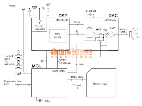
View full Circuit Diagram | Comments | Reading(1963)
The radio circuit of the frequency LCD display (2)
Published:2011/6/10 1:08:00 Author:Seven | Keyword: radio circuit, frequency LCD display
View full Circuit Diagram | Comments | Reading(1515)
The chat transfer device of collinear phones (1)
Published:2011/6/10 1:04:00 Author:Seven | Keyword: chat transfer, collinear phones
View full Circuit Diagram | Comments | Reading(520)
| Pages:1770/2234 At 2017611762176317641765176617671768176917701771177217731774177517761777177817791780Under 20 |
Circuit Categories
power supply circuit
Amplifier Circuit
Basic Circuit
LED and Light Circuit
Sensor Circuit
Signal Processing
Electrical Equipment Circuit
Control Circuit
Remote Control Circuit
A/D-D/A Converter Circuit
Audio Circuit
Measuring and Test Circuit
Communication Circuit
Computer-Related Circuit
555 Circuit
Automotive Circuit
Repairing Circuit