
Circuit Diagram
Index 1771
The chat transfer device of collinear phones (2)
Published:2011/6/10 1:10:00 Author:Seven | Keyword: chat transfer, collinear phones
View full Circuit Diagram | Comments | Reading(562)
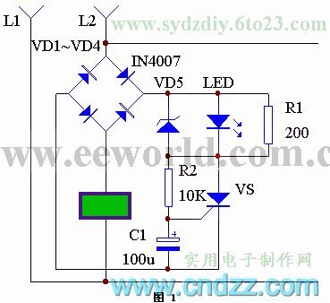
The circuit of a new type of electric mouse killer
Published:2011/6/10 1:27:00 Author:Seven | Keyword: electric mouse killer
It is said that mice are sensitive to magnetic field, which is why common high-voltage girds have bad effects on killing mice. The mice killer in the text has no high voltage ordinarily, so it won't cause the warning of mice, however, once mice touched the grid, the grid would generates a high voltage and kill the mice quickly. See as the figure, 1B is a separating and boost transformer. As the grid takes the earth as a pole, to prevent the mains protector from mistaking actions, the transformer is separated from the mains circuit. (View)
View full Circuit Diagram | Comments | Reading(928)
The portable phone wire distributor
Published:2011/6/10 1:19:00 Author:Seven | Keyword: phone wire, distributor
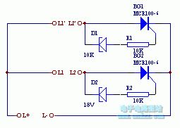
MCK100
(View)
View full Circuit Diagram | Comments | Reading(531)
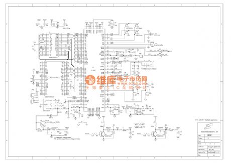
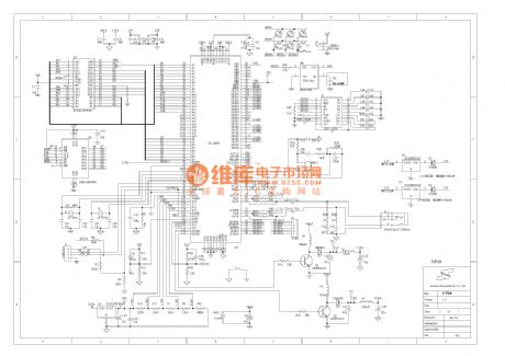
The principle diagram of IC reader/writer
Published:2011/6/10 1:11:00 Author:Seven | Keyword: principle diagram, IC reader/writer
This is a IC card and its reader/writer circuit, in which the reader/writer consists of a MPU, key board, display, supervision circuit and so on. The IC card is X76F100Y of XICOR.
2.1 the IC and its connectorX76F100 is a secure series FLASH E2PROM of 128*8 bit, of which either of the reader code and encoder code is 64 bit. The package pin of the smart card is as shown in Figure 2. The chip is packaged on a card, and the card is inserted into the connector of the IC reader, then the reader/writer and fulfills functions of encodeing, checking, saving,withdrawing and so on. (View)
View full Circuit Diagram | Comments | Reading(641)
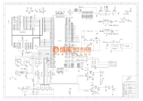
The MP3 hardware principle circuit (10)
Published:2011/6/10 1:12:00 Author:Seven | Keyword: hardware, principle circuit
View full Circuit Diagram | Comments | Reading(576)
The MP3 hardware principle circuit (09)
Published:2011/6/10 1:13:00 Author:Seven | Keyword: principle circuit
View full Circuit Diagram | Comments | Reading(575)
The MP3 hardware principle circuit (08)
Published:2011/6/10 1:20:00 Author:Seven | Keyword: principle circuit
View full Circuit Diagram | Comments | Reading(570)
The MP3 hardware principle circuit (06)
Published:2011/6/10 1:20:00 Author:Seven | Keyword: principle circuit
View full Circuit Diagram | Comments | Reading(587)
The MP3 hardware principle circuit (05)
Published:2011/6/10 1:22:00 Author:Seven | Keyword: MP3 hardware
View full Circuit Diagram | Comments | Reading(588)
the MP3 circuit(2)
Published:2011/6/10 1:22:00 Author:Seven | Keyword: MP3 circuit
View full Circuit Diagram | Comments | Reading(692)
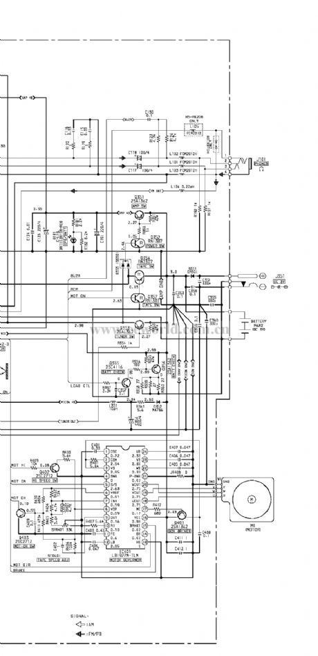
The Aiwa walkman hs-rx 108 circuit
Published:2011/6/10 1:26:00 Author:Seven | Keyword: Aiwa walkman
View full Circuit Diagram | Comments | Reading(1254)
The massager circuit of SCH
Published:2011/6/10 1:27:00 Author:Seven | Keyword: massager circuit
The massager circuit of SCH (View)
View full Circuit Diagram | Comments | Reading(538)
The USB multi-media of 2.5W+2.5W
Published:2011/6/10 1:28:00 Author:Seven | Keyword: USB multi-media
Brief description: it doesn't need an external power supply or a sound card, and the cost is 20 yuan.
(View)
View full Circuit Diagram | Comments | Reading(549)
The common sound circuit of color TV: TDA7057
Published:2011/6/10 1:29:00 Author:Seven | Keyword: sound circuit
Pin functions and reference voltage of TDA7057: 1-pin:0~1v----DC sound volume control 12-pin:0v----empty3-pin:2v----input 14-pin:19v----power supply5-pin:2v----input 26-pin:0v----signal GND7-pin:0~1v--DC sound volume control 28-pin:8.6v----positive output 29-pin:0v----power amplifier GND 210-pin:8.6v----negative output 111-pin:8.6v----negative output 212-pin:0v----power amplifier GND13-pin:8.6v----positive output 1 (View)
View full Circuit Diagram | Comments | Reading(1779)
The common sound circuit of color TV: TDA2009
Published:2011/6/10 1:29:00 Author:Seven | Keyword: sound circuit, color TV
TDA2009I-pin:1.2v----left channel input; 2-pin:0.8v----left channel feedback; 3-pin:12v----mute/noisy;4-pin:0.8v----right channel feedback; 5-pin:1.2v----right channel feedback; 6-pin:0v----ground; 7-pin:0v----empty; 8-pin:12.4v----right channel output; 9-pin:24v----power supply; 10-pin:12.4v----left channel output;11-pin:---- (View)
View full Circuit Diagram | Comments | Reading(699)
The common sound circuit of color TV: TDA1521
Published:2011/6/10 1:30:00 Author:Seven | Keyword: sound circuit
This circuit is from Changhong C2191, which is of OTL dual-channel connectionPin functions and reference voltage of TDA1521:1-pin:11v----backward input(L channel signal input);2-pin:11v----forward input 1;3-pin:11v----reference 1(it's 0v when it is in OCL connection, and it's 1/2Vcc when it's in OTL connection );4-pin:11v----ouput 1(L channel signal output);5-pin:0v----negative power supply input(it connects with the earth when it is in OTL connection ); 6-pin:11v----output 2(R channel signal output);7-pin:22v----positive power supply input; 8-pin:11v----positive input (View)
View full Circuit Diagram | Comments | Reading(608)
The common sound circuit of color TV: TDA1013B
Published:2011/6/10 1:30:00 Author:Seven | Keyword: sound circuit
Pin functions and reference voltage of TDA10131-pin:0v----earth;2-pin:7.7v----sound output; 3-pin:16v----power supply; 4-pin:13.5v----power supply; 5-pin:0.3v----power supply; 6-pin:6.7v----pre-output; 7-pin:2.8v----sound volume control; 8-pin:1.9v----audio input; 9-pin:0v----earth (View)
View full Circuit Diagram | Comments | Reading(619)
The common sound circuit of color TV: TA8218AH
Published:2011/6/10 1:31:00 Author:Seven | Keyword: sound circuit, color TV
Pin functions and reference voltage of TA8218AH1-pin:1.9v----backward input terminal; 2-pin:3-pin:0v----earth; 4-pin:1.9v----backward input terminal;5-pin:2.1v----heavy low-frequency audio signal input;6-pin:2.1v----L channel audio signal input;7-pin:1.9v----backward input terminal;8-pin:8.9v----filter;9-pin:26v----power supply; 10-pin:13v----L channel audio signal output; 11-pin:4.7v----mute;12-pin:4.5v----empty;13-pin:0v----earth; 14-pin:13v----heavy low-frequency audio signal output (View)
View full Circuit Diagram | Comments | Reading(683)
Sound circuit: AN5265
Published:2011/6/10 1:32:00 Author:Seven | Keyword: Sound circuit
Pin functions and reference voltage of AN52651-pin:12V----pre-stage power supply; 2-pin:5v----audio signal input terminal;3-pin:0v----mute control terminal(it's mute when it is in a high LEV);4-pin:0.1V----input terminal of sound volume control voltage;5-pin:7v----wave filter; 6-pin:7.4v----negative feedback input pole; 7-pin:0v----earth; 8-pin:7.5v---- the output pole of power amplifier; 9-pin:15-----power supply of power amplifier (View)
View full Circuit Diagram | Comments | Reading(717)
The dual sound door bell without battery
Published:2011/6/10 1:32:00 Author:Seven | Keyword: door bell
47.The dual sound door bell without batteryAs the popularity rate of phones is higher and higher, more and more homes have domestic phones, however, usage rate is low, therefore, it's economic to use the 48v(60v) DC current of phones as the working energy. Now we introduce a dual sound door bell without battery, the circuit principle is shown in the figure. From the figure, we can see that the circuit is changed from the common circuits of phone rings. a and b are the positive and negative poles of phone wires, respectively.
(View)
View full Circuit Diagram | Comments | Reading(557)
| Pages:1771/2234 At 2017611762176317641765176617671768176917701771177217731774177517761777177817791780Under 20 |
Circuit Categories
power supply circuit
Amplifier Circuit
Basic Circuit
LED and Light Circuit
Sensor Circuit
Signal Processing
Electrical Equipment Circuit
Control Circuit
Remote Control Circuit
A/D-D/A Converter Circuit
Audio Circuit
Measuring and Test Circuit
Communication Circuit
Computer-Related Circuit
555 Circuit
Automotive Circuit
Repairing Circuit