
Circuit Diagram
Index 1774
Welder no-load power saver circuit diagarm 9
Published:2011/6/10 3:40:00 Author:Lucas | Keyword: Welder, no-load, power saver
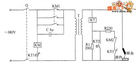
The welder no-load power saver circuit is composed of the knife switch Q, AC contactor KM, buck capacitor C, keeping resistor R1, starting resistor R2, time relay KT, welding transformer T, and the circuit is shown as the chart. Turning on the knife switch Q will make AC contactor KM get power and pull in, and its normally open contacts KM1 and KM2 are connected, then the welder can do the normal work. R1 and R2 select the 20W wire-wound resistor. C uses the CBB capacitor or oil capacitor with the voltage being 630V. KT selects the time relay with the coil voltage in 24V, such as JS7-2A type. KM selects the AC contactor with the coil voltage being 380V (or 220V) . The use of Q can be according to the power of T.
(View)
View full Circuit Diagram | Comments | Reading(1314)
Welder no-load power saver circuit diagarm 2
Published:2011/6/10 5:58:00 Author:Lucas | Keyword: Welder , no-load , power saver
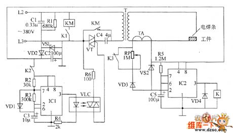
The welder no-load power saver circuit is composed of the power supply circuit, pulse oscillator, monostable trigger and control circuit and other components, and the circuit is shown as the chart. Power supply circuit consists of step-down capacitor C1, resistor R1, Zener diode VS1, rectifier diode VD2 and filter capacitor C2 and so on. Pulse oscillator is composed of the time-base integrated circuit IC1 and external components. Monostable trigger is composed of the time-base integrated circuit IC2, capacitor C5 and resistor R5 and so on. Control circuit is composed of the optical coupler VLC, relay K, AC contactor KM and Triac VT and other components. R1 uses 1W carbon film resistor: R2 ~ R6 select 1/4W carbon film resistors. RP uses solid potentiometer. C2, C3 and C5 select the aluminum electrolytic capacitors with the voltage being 16V.
(View)
View full Circuit Diagram | Comments | Reading(1452)
the control circuit of electric fence part 8
Published:2011/6/2 6:20:00 Author:Ariel Wang | Keyword: control, electric, fence
After the mains switch S1 gets through, autogenerator works.It generates oscillating impulse voltage on the W2's winding of T1.The oscillating impulse voltage is commutated by VD1 and VD4.It charges C10 by R6.When C10 is full charged and the voltage through C10 reaches +320V,the 2nd-pin of IC1 becomes high level.The autogenerator stops.When the metal wire of the electric fence is not touched by any animals ,IC2 is conducted.C5 is charged.V1 and VU are off condition.The trigger control circuit has no voltage output.VT is not conducted.There is no pulsed high voltage generated on the W4's winding of T2.The alarm circuit doesn't work.VL is not lighted. HA doesn't ring.
(View)
View full Circuit Diagram | Comments | Reading(2846)
the control circuit of electric fence part 7
Published:2011/6/3 8:21:00 Author:Ariel Wang | Keyword: control, electric, fence
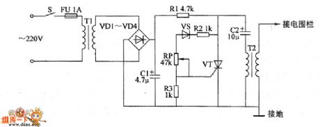

The AC 220V voltage is reducted by T1 isolated.It is commutated by VD1-VD4.It is filtered by C1.And it is current limited by R1.It charges C2.It is branched by R2,VS,RP and R3.It provides trigger voltage for VT's gate.When the voltage of C2 is charged to a certain value,VT is triggered to conduct.C2 discharges on VT and the first winding of T2.After C2 discharges,VT stops.C2 begins to charge,so VT conducts……It goes over and over again.It will generate kilovoltage pulsed high voltage on the second winding of T2.The high voltage of the electric fence will give the animal touching it an electric shock.
(View)
View full Circuit Diagram | Comments | Reading(2008)
the control circuit of electric fence part 5
Published:2011/6/5 19:38:00 Author:Ariel Wang | Keyword: control, electric, fence
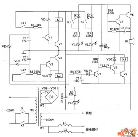
The 6V AC voltage is commutated by VD8-VD11.It is filtered by C5.It provides +6V working voltage for triggering the control circuit and protecting the circuit.It is reduced by R9,and it will go to VL3.Then it lights VL3.The 1500V AC voltage goes to the aerial bare metal line of electric fence by control turns L1 and L2.If the aerial bare metal line is not touched by any animals and there is no current in the control turns L1 and L2 ,control contacts of reed switches SA1 and SA2 are off state.V1-V4 stop.K1 and K2 are at release position.The alarm circuit is not working.VL1 and VL2 are not be lighted.BL don't give a sound.
(View)
View full Circuit Diagram | Comments | Reading(627)
the circuit of electrifying intermittent controller part 2
Published:2011/6/5 20:34:00 Author:Ariel Wang | Keyword: electrifying, intermittent, controller
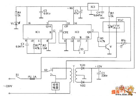
After the multivibrator conducted to work, the output cycle from 3rd-pin(Q14 end) of square-wave pulse is 1 min.It is the counting pulse of the 14th-pin of IC2.It outputs a high level every 10 min or 6 min(position 53 on 1 ,the control circuit will work for 1 min every 10 min;position 53 on 2 ,the control circuit will work for 1 min every 6 min).V will conduct when the 3rd-pin of IC2 outputs high level.It will light LED inside VLC.The photo-thyristor will conduct by exposed to sunlight.The controlled electric appliance will be conducted to work.
(View)
View full Circuit Diagram | Comments | Reading(538)
the circuit of timing controller part 2
Published:2011/6/8 9:19:00 Author:Ariel Wang | Keyword: timing , controller
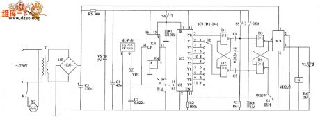
When you reach the timing time (5min),it outputs high level from Y5 end of IC2.The trigger ItS overturns to D1.D4 outputs high level.D2 and D3 output low level.K releases.The normally open contacts cut off the working power supply of load.At the same time,VL dies out.At this moment,if S3 at the position 9 of single timing ,then the time of timing goes back.IC2 stops counting.If S3 at the position of circulation ,then IC2 goes on counting.After 5MIN,the end of YO outputs high level.Trigger RS overturns.K pulls back again. The load is conducted to work.The timing time (5min) goes back,Y5 end of IC2 outputs high level,trigger ItS overturns again……The circle goes on,the load intermittent works.
(View)
View full Circuit Diagram | Comments | Reading(573)
the circuit of humidity detector for food part 1
Published:2011/6/8 16:18:00 Author:Ariel Wang | Keyword: humidity , detector, food
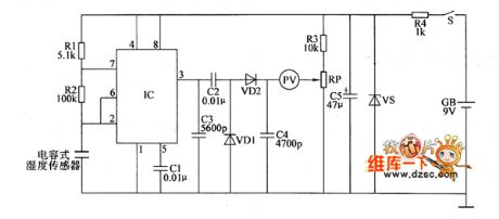
When to be detected,the foodstuffs are put into the space between two metal plates of the capacitive humidity sensor.The humidity amount of foodstuffs is changing as the capacity changes.Then the oscillation frequency of multivibrator is changing as well.The shortwave signal which outputs from the pin-3 of IC becomes triangular wave signal.It becomes DC voltage after it is commutated by VD1 and VD2.It reveals itself through voltmeter PV(the more amount of the food humidity,the larger capacity of the sensor,and the higher of the voltage PV displays).
(View)
View full Circuit Diagram | Comments | Reading(483)
the circuit of the timing controller part 1
Published:2011/6/8 23:22:00 Author:Ariel Wang | Keyword: timing, controller
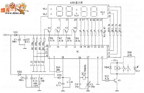
S1 is used to change the time set,the walking state and the timing set of the timing controller.When it's at state of time set,S2 is used to convert and regulate the position of hours and minutes. S3 is used to quicken the time.S4 is used to slow down the time.When to set the timing time,S2 can convert and set the work station of whether work or not at some timing time.At the state of walking,S2 is used to enter or exit the manual state.S3 is used to turn the power of the equipment on.S4 is used to shut down the power of the equipment.
(View)
View full Circuit Diagram | Comments | Reading(486)
the substitute circuit of electric motor centrifugal switch part 2
Published:2011/6/9 0:14:00 Author:Ariel Wang | Keyword: substitute, electric, motor, centrifugal, switch
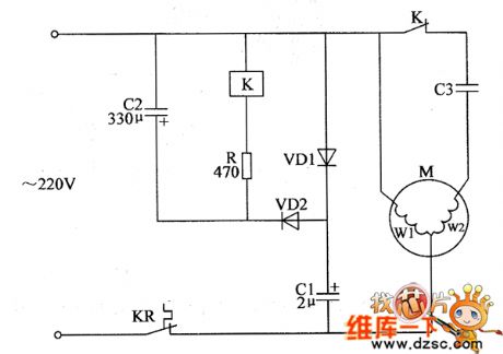
When power supply gets through,the voltage can't change suddenly as the capacity of CZ is larger.And the relay K can't pull in.After a few minutes,the voltage of C2 is charged to a certain value(when the input AC voltage is in the positive half cycle ,it charges C1 by VD1.When the input voltage is in the negative half cycle,the voltage charged by C1 and input voltage are added together.Then it charges C2 by VD2. )K is conducted to pull in.The normally-closed contacts are disconnected.It breaks the starting circuit of M.The main winding of M works alone.It completes the starting process of electric motor.
(View)
View full Circuit Diagram | Comments | Reading(1030)
the control circuit of electric fence part 1
Published:2011/6/9 7:07:00 Author:Ariel Wang | Keyword: control, electric, fence
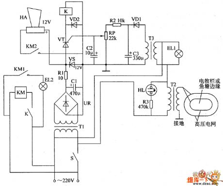
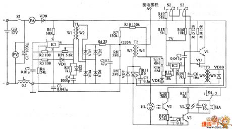
When the mains switch gets through,the 220V AC voltage is reduced by T1,commutated by UR,filtered by C1,current limited by R1 and regulated by VS.Then it generates 12V DC voltage.It is the power supply for the working of alarm HA and relay K.EL1 and the primary winding T3 are parallel connected.They and the primary winding of transformer booster T2 are series connected.After S gets through,neon indicator HL is lighted.But EL1 is not shining as the electric current passing through is too small.There's no voltage output on the secondary winding of T3.The secondary winding of T2 generates the induced voltage of 4000-6000V.
(View)
View full Circuit Diagram | Comments | Reading(1124)
the substitute circuit of electric motor centrifugal switch part 1
Published:2011/6/10 7:28:00 Author:Ariel Wang | Keyword: substitute, electric, motor, centrifugal, switch
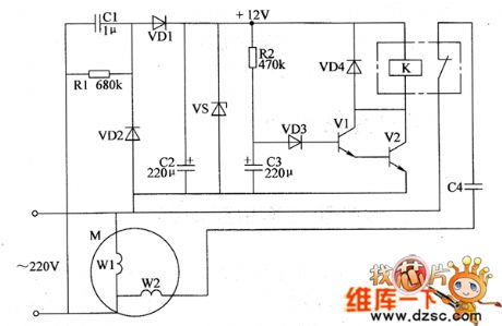
When the power supply is connected,the voltage of C3 can't be changed suddenly.V1 and V2 are stopped.K is at the release condition.The normally closed contacts is connected.The secondary winding W2 of electric motor M(starting winding) and the start capapcitor C4 enter to the circuit by the normally closed contacts.The electric motor M starts to operate.When it's about 6s,the rotational speed reaches 75% to 80% of rated speed.The voltage of C3 is charged to about 1.8V.V1 and V2 are saturated to conduct.K is conducted to pull in.The normally-closed contacts are disconnected.It disconnects the secondary winding W2 of M and C2 with the power circuit.At this time the main winding works alone.The electric motor starts.
(View)
View full Circuit Diagram | Comments | Reading(2736)
The circuit diagram of emergency lamp circuit board
Published:2011/5/24 23:36:00 Author:Ariel Wang | Keyword: emergency lamp, circuit board
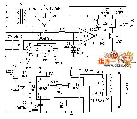
When we make it,X1selects secondary power transformer 6V/200mA for use. J1 and J2 use the relay of 6V coil voltage.Othe device selection you can refer to the diagram. There's no other requirements.It's very easy for circuit debugging.When main power supply is connected.J2 should act.LED1 is the indication of power supply. Then measurethe 3 leg voltage ,see if it is around 6.9V.After that it's possible to use external power to access IC 2 feet to adjust chargement to protect circuit. When input voltage is beyond 6.9V,J1 should disconnect . When S1 is disconnected,you can use external power to access emergency lamp circuit.Then you can measurewhether the output of IC2 is 50Hz or not.Then it's possible to measure wether partial output voltage of X2 is around 220V.LED3 is theprediction ofwhether it is power failure or normal working status of emergency lamp.
(View)
View full Circuit Diagram | Comments | Reading(2677)
the circuit of zero cross detection
Published:2011/5/27 8:20:00 Author:Ariel Wang | Keyword: zero cross , detection
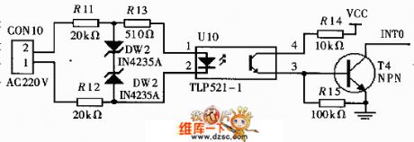
The AC 220V goes to branch current circuit by resistor . Then the branch voltage goes to photocoupling.Let's suppose we input line-to-neutral voltage A .When line-to-neutral voltage A is converting from negative half period to positive half period. It will generates the pulse on the trailing edge.The pulse goes to ADμC812's INTO pin.That makes the system enter the suspending progress.When the micro system entering the suspending progress,it will give a sampling command. And it will read the value reactive current Iqm.The reactive current is A's reactive current.It will reach the max value through 1/4 cycle.At this time,if you sample the voltage,you will get UM. If UM=1.414U,you can get the virtual value U of the voltage.
(View)
View full Circuit Diagram | Comments | Reading(3375)
switching-regulator circuit reformed by waste energy-saving lamp
Published:2011/5/24 23:45:00 Author:Ariel Wang | Keyword: switching-regulator circuit, waste, evergy-saving lamp
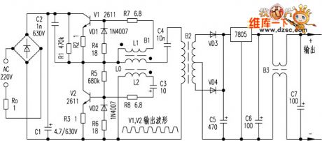
When it isbeingused,it's not proper to take voltage from C5 directly. It's imposible to allow short circuit happened, otherwise it'll burn V1 and V2. Because when short circuit takes place,the electric currentin coil LO of flyback transformer B1 will increase rappidly.The voltage of coil L1 and L2 increases to a rather high level.It gives back the electric currentin V1 and V2 increasing as well. It causes intensive positive feedback.Finally it burns out as the limitation of power consumption of V1 and V2. This feedback of circuit belongs to series circuit feedback.And it can openand protectcircuit. But when load is increased,the feedback is strenghened.What's more,the frequency will decrease as the load increases. The internal resistance is rather small,so short circuit will burn pliotron very easily.
(View)
View full Circuit Diagram | Comments | Reading(1030)
555 light control stroboscopic type security light circuit
Published:2011/5/22 8:14:00 Author:TaoXi | Keyword: light control, stroboscopic type, security light
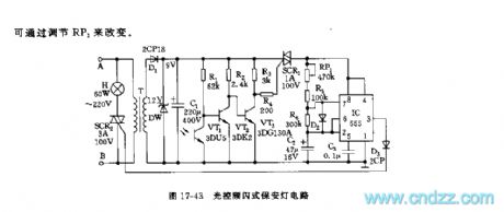
As the figure 17-43 shows, the circuit is composed of the step-down rectifier circuit, the photoelectric switch circuit and the stroboscopic oscillation & control circuit, this circuit can be used in wide range of applications such as the construction scene and the road scene to remind the people to pay attention.
At night, the photoelectric switch circuit which is composed of the 3DU5, the VT2 and VT3 amplifiers is in the conduction state, SCR1 triggers the conduction, the IC oscillator starts working, it conducts and cuts off the SCR2 with its oscillation frequency, so the lamp H shines to remind the people. The light flash frequency f=1.44/(RP1+R5+R6)C2.
(View)
View full Circuit Diagram | Comments | Reading(923)
555 amplification exposure time automatic controller circuit
Published:2011/5/24 2:53:00 Author:TaoXi | Keyword: amplification, exposure, time, automatic controller
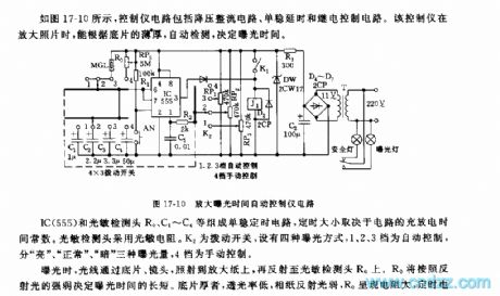
As the figure 17-10 shows, the controller circuit is composed of the step-down rectifier circuit, the monostable delay circuit and the relay control circuit. When the controller is amplifying the photo, it can automatic detect the thickness of the negative film to decide the exposure time.The monostable timing circuit is composed of the IC(555) and the photosensitive detection head R0, the C1~C4.etc.
The timing length is determined by the circuit's charge-discharge time constant. The photosensitive detection head uses the photoconductive resistance, K2 is the toggle switch and it has four kinds of exposure method, 1,2,3 tap positions are the automatic control, there is three kinds of exposure value: light , normal and dark , the fourth gear is the manual control gear.
(View)
View full Circuit Diagram | Comments | Reading(603)
555 automatic circulating seven colors color-light control circuit
Published:2011/5/22 19:55:00 Author:TaoXi | Keyword: automatic circulating, seven colors, color-light, control circuit
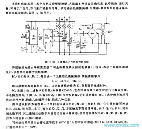
This color-light circuit uses the three-color light bulb which is controlled by the frequency divider, it has eight kinds of combination luminous states, it is colorful and unpredictable. So this circuit can be used in wide range of applications such as the advertising lights, the holiday lights and the decorative lights. This circuit is composed of the low frequency oscillator, the frequency divider, the trigger control circuit and the step-down rectifier circuit.etc. As the figure 17-58 shows.
The step-down rectifier circuit is composed of the step-down transformer T, the bridge rectifier and the filter capacitor C4.
The no steady-state low-frequency oscillator is composed of the IC1(555) and R1,R2,C1, the oscillation frequency fc=1.44/(R1+2R2)C1.
(View)
View full Circuit Diagram | Comments | Reading(781)
555 big white mouse training
Published:2011/5/24 2:53:00 Author:TaoXi | Keyword: big white mouse, training, lost box
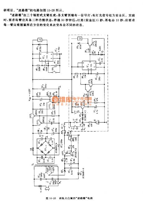
The lost box is composed of three radiant arms, on the top of each arm there is a signal light, the zone which has the light signal is the safety zone. In the experiment, we require each arm should have three functions.
The lost box circuit is composed of the step-down voltage stabilization circuit, the constant-current source circuit, the timing sequence control circuit and the three-channel trigger control circuit.etc.
The multivibrator is composed of the IC4(555) and 4R1,4R2,4C1, it is used as the timing sequence control circuit, the oscillation period T=0.693(R1+2R2)C1, the tcharging=0.693(R1+R2)C1, it is about 30 seconds, so the high level output time is 30 seconds; tdischarging=0.693R2C1, it is about 15 seconds.
(View)
View full Circuit Diagram | Comments | Reading(730)
555 ozone tube electronic disinfection circuit
Published:2011/5/23 8:22:00 Author:TaoXi | Keyword: ozone tube, electronic disinfection
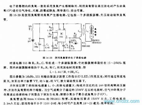
The figure 16-39 shows the ozone generator circuit with the ozone tube, it is composed of the multivibrator, the boost driver stage and the ozone tube.
The multivibrator is composed of the time base circuit 555 and the R1,R2,C3, it's oscillation frequency is preferably between the 15-20kHz, the oscillation frequency in the figure depends on the R1, R2 and C3's charging and discharging time constant, fc=1.44/(R1+2R2)C3.
The parameter of the figure is 18kHz. The 555 output oscillation square wave makes the indicator light to shine, at the same time this square wave adds to the b pole of the VT1 power transistor through the current limiting resistor R4, and then it is amplified by VT1 to drive the transformer T.
The ozone tube uses the 8mm X 63mm H63815 type tube, the terminal voltage is about 1500V, the working current is about 2.3mm,and the service life is not less than 1500 hours.
(View)
View full Circuit Diagram | Comments | Reading(1664)
| Pages:1774/2234 At 2017611762176317641765176617671768176917701771177217731774177517761777177817791780Under 20 |
Circuit Categories
power supply circuit
Amplifier Circuit
Basic Circuit
LED and Light Circuit
Sensor Circuit
Signal Processing
Electrical Equipment Circuit
Control Circuit
Remote Control Circuit
A/D-D/A Converter Circuit
Audio Circuit
Measuring and Test Circuit
Communication Circuit
Computer-Related Circuit
555 Circuit
Automotive Circuit
Repairing Circuit