
Circuit Diagram
Index 1769
The protection circuit of 555 fridge
Published:2011/6/7 4:13:00 Author:Borg | Keyword: protection circuit
See as Figure 13-8, the protector is formed by sub-circuits of the step-down rectifier, delay starter, over/low voltage sample and trigger,etc. The protector has functions of over voltage (>245v) and low voltage(<175v) protection, off-delay operation(about 7 minutes) and so on, and it's power saving(<2w) and cost saving.
Figure 13-8. Theexternalprotection circuit of fridges
IC(555), R4 and C3 consist the single steady delay circuit, the delaying time is td=1.1R4C3, the delaying time of the parameter in the figure is about 7min. When the circuit is protecting the fridge, LED1(red) is glowing, and the fridge outlet is cut off; when it is working normally, LED2(green) is glowing.
(View)
View full Circuit Diagram | Comments | Reading(634)
The reminder circuit of opening door too long of 555 fridge
Published:2011/6/7 4:15:00 Author:Borg | Keyword: reminder circuit, 555 fridge
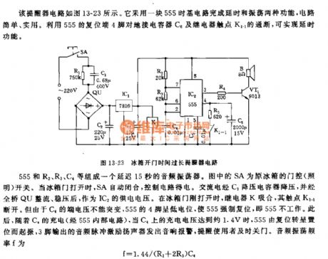
The reminder circuit is shown in Figure 13-23. It is a 555 timing circuit which fulfills two functions of time delay and oscillation, and it is simple and useful. With the use of 4-lead reset terminal linking to the ground connection capacitor C4, and the switching of relay connector K1-1, it can fulfill the function of time delay.
Figure 13-23 The reminder circuit of opening door too long of fridges
555,R2,R3 and C4 consist an audio oscillator which delays time for 15s. SA in the figure is the door control(light) switch of the former fridge. When the fridge door is open, SA will automatically close and the control circuit will get the power. (View)
View full Circuit Diagram | Comments | Reading(749)
The control circuit of 555 multiple fridge
Published:2011/6/7 4:27:00 Author:Borg | Keyword: control circuit
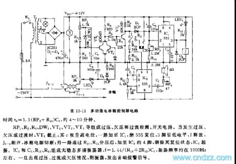
See as Figure 13-11, the control circuit includes sub-circuits of over voltage sampling, low voltage sampling, time delay starter,sound & light alarm device and step-down rectifier, etc. Its main functions are auto protection of over voltage, low voltage and over current, delaying starting of instant power-off, light&sound alarm for faults and so on. IC1(555),C6,R14,RP3 and so on form a time delay starting circuit, when the fridge is power-on, or it is power-off then the power is on again, as the voltage on C6 can not mute, only when RP3 and R14 charge C6 and the LEV of C6 is lower than the 2-lead trigger LEV of 1/3VDD does 555 reset and J pull in.
(View)
View full Circuit Diagram | Comments | Reading(531)
The 555 double-cylinder washing machine timer and washing mode selector circuit
Published:2011/6/7 4:30:00 Author:Borg | Keyword: double-cylinder, washing machine, washing mode
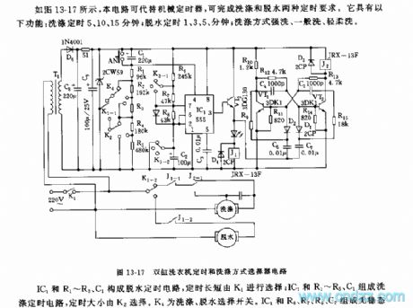
See as Figure 13-17, this circuit can replace machine timers, which can fulfill washing and dehydrating. It is equipped with functions of washing timing for 5,10 and 15min; dehydrating for 1,3 and 5 min; washing modes of power washing, general washing and slight washing.
Figure 13-17 the double-cylinder washing machine timer and washing mode selector circuitIC1,R1~R3 and C1 form the dehydration timing circuit, the time span is selected by K1; IC1,R1~R5 and C1 consists the washing timing circuit, the time span is chosen by K2. K4 is the washing/dehydrating switch. (View)
View full Circuit Diagram | Comments | Reading(2230)
The protection outlet circuit of 555 small-sized fridge
Published:2011/6/7 4:31:00 Author:Borg | Keyword: protection outlet circuit, small-sized fridge
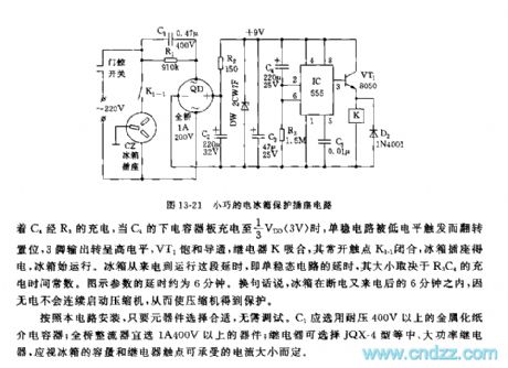
The circuit is based on 555, which has the virtues of small size, low cost and reliable time delay. The circuit consists of step-down rectifier circuit, time delay circuit and relay controller circuit, etc, which is as shown in Figure 13-21. The step-down rectifier circuit consists of step-down capacitor C1,C2 and full bridge circuit QD, C2 and so on , the rectified voltage is stabilized by R2 and DW and then becomes a DC voltage of +9V, finally, it becomes the working voltage of the next circuit.555,C4 ,R3 and so on consist a single steady time delay circuit.
Figure 13-21 The protection outlet circuit ofthe small-sized fridge (View)
View full Circuit Diagram | Comments | Reading(628)
The simple natural wind analog circuit
Published:2011/6/7 4:33:00 Author:Borg | Keyword: natural wind, analog circuit
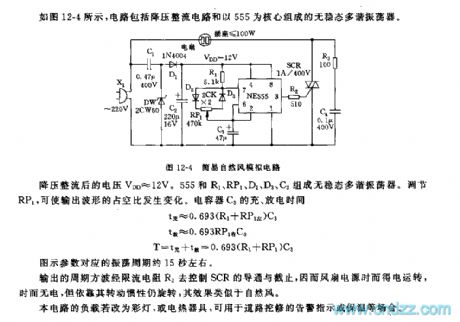
See as Figure 12-4, the circuit includes a step-down rectifier current and a 555-based non-steady multi-resonate oscillator.
The voltage after being rectified is VDD≈12V. 555,R1,RP1,D2,D3 and C3 consist a non-steady multi-resonate oscillator. By adjusting RP1, we can change the duty cycle of the output wave.
The output period square wave controls the conduction and end of SCR by the current limited resistance R2, so the power supply of the fan gets power now and then, but it keeps rotating due to the inertia, and the result is like the natural wind. (View)
View full Circuit Diagram | Comments | Reading(670)
The 555 analog natural wind control circuit of Meifeng fan
Published:2011/6/1 3:25:00 Author:Borg | Keyword: natural wind, control circuit
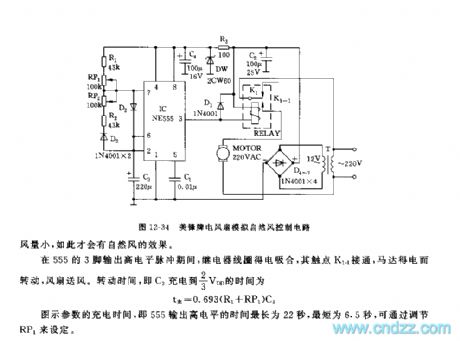
The circuit is shown in Figure 12-34, which consist of sub-circuits of AC step-down rectifier, low-frequency non-steady multi-resonate oscillator and relay controller motor, etc. This circuit is simple. And the simulated wind is vivid, it is strong sometimes or weak other times, so the effect is good.The time-based 555 circuit, R1,R2,RP1,RP2,C3 and so on consist a non-steady multi-resonate oscillator, the oscillating frequency is very low, which is
T=0.693(R1+RP1+R2+RP2)C3
The oscillating period of the parameter in the figure ranges 13~44s, which can be regulated by adjusting RP1 and rp2.
(View)
View full Circuit Diagram | Comments | Reading(630)
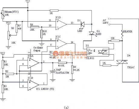
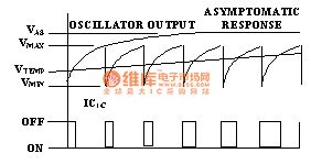
Constant temperature controller circuit with the four-comparator
Published:2011/5/17 21:38:00 Author:TaoXi | Keyword: Constant temperature, controller, four-comparator
Related components PDF download:
LM339TIL3011
This controller is the PWM type, but it has the index transfer characteristics but not the linearity. This design is based on a LM339 (four-comparator) and contains the temperature compensation. Because the comparator's temperature drift will produce the Vos change and cause the change the oscillator output. However, in the comparator of producing the working cycle, the same change has taken place, they offset each other to eliminate the drift of the controller.
The core of the controller is the oscillator which is composed of the IC1a, IC1b and other related components. The main factors of the controller precision are the peak value and the minimum voltage of the oscillator's output voltage. The oscillator has the following formulas:
PERIOD=[R5×R6/(R5+R6)+R4]×C1×Ln[(Vas-Vmin)/(Vas-Vmax)] seconds
DutyCycle=Ln[(Vas-Vtemp)/(Vas-Vmax)] / Ln[(Vas-Vmax)/(Vas-Vmin)]
Vmax=Vcc×R3/(R1+R3)
Vmin=Vcc×R2×R3/[R2×R3+R1×(R2+R3)]
Vas=Vcc×R6/(R5+R6)
Vtemp=Vcc×(R7+R8)/(Rtherm+R7+R8)
Figure 1. Constant temperature controller circuit
(View)
View full Circuit Diagram | Comments | Reading(1797)
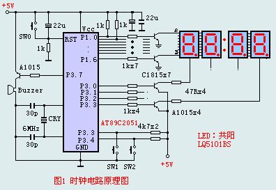
The clock timing principle circuit
Published:2011/5/17 22:52:00 Author:TaoXi | Keyword: clock, timing, principle circuit
Related components PDF download:
AT89C2051A1015C1815
In the internal RAM of the single chip microcontroller, we need to set the display buffers, the hours, minutes and seconds values are took out from the display buffers, so we set four units as the display buffers in RAM, they are 7AH,7BH and 7CH. To make the circuit and the principle narrative more convenient, we don't display the second value, we realize the second binary by flashing score. So we have 4 bits LEDs to display the hour value and the minute value. Meanwhile all the clocks need to be calibrated. The program also needs to install the display code meter.
(View)
View full Circuit Diagram | Comments | Reading(709)
Infrared heating device temperature control circuit
Published:2011/5/18 10:31:00 Author:TaoXi | Keyword: Infrared, heating device, temperature control
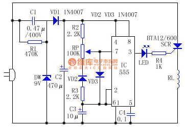
Working principle: the circuit is as shown, IC (555) connects to the low frequency oscillator, by adjusting RP, you can change C3's recharging time constant, and the pin-3's output pulse duty ratio also changes too, that changes the ratio of the SCR conduction and closing time, and also control the average power of the heating pipe RL to achieve the temperature control purpose.
When RP is adjusted to the top value, the IC output pulse duty ratio is about 0 , RL gets the minimum power; When RP is adjusted to the lowest value, the IC output pulse duty ratio is about 1 , RL gets the maximum power. So you can make the IC output pulse duty ratio continuous changes between 0 and 1 .
(View)
View full Circuit Diagram | Comments | Reading(1593)
The 555 electronic ventriloquism circuit
Published:2011/5/27 2:49:00 Author:nelly | Keyword: electron, ventriloquism, sound circuit
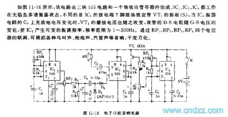
As shown on the figure 11-18, this circuit consists of three 555 circuits and a field effect transistor. IC1, IC2 and IC3 all work in the state that is unsteady and multi-vibration, the difference is that IC2's discharge end 7 foot contacts the field effect transistor VT1's source. When the C7's voltage on the IC3 oscillation circuit changes, the VT1's grid voltage also changes. This electrical resistance D-S changes with the voltage G-S, which leads IC2 to produce the variable oscillation frequency, the frequency is between 1Hz and 300Hz. It can simulate many kinds of sounds through the integrated test among the potential including RP1, RP2, RP3, RP4. (View)
View full Circuit Diagram | Comments | Reading(634)
The 555 touching nose game circuit
Published:2011/5/27 2:48:00 Author:nelly | Keyword: 555, touching nose, circuit
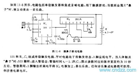
The Monostable trigger circuit consists of the 555, R1 and C1. The circuit doesn't be triggered ordinarily and its three foot is low level. When the body touchs the biyu , the 555 will flip, and then get into the triplet state. The temporary stability time : td=1.1R1C1, the corresponding pulse width to the figure is about 10s. In the triplet state, the high level which is output by the three foot combines with the IC2 and plays music. Every music IC all can use it, but we must notice the voltage. (View)
View full Circuit Diagram | Comments | Reading(570)
The single pole sound signal generator circuit
Published:2011/6/10 3:36:00 Author:Seven | Keyword: single pole, sound signal generator
14.15 the single pole sound signal generator circuit See as Figure 14-15, the circuit is installed with an integrated oscillator circuit of 566 pressure control, and the circuit can generate a pulse train which lasts for 0.5s. The frequency of the pulse is f=1/3R1C1.
(View)
View full Circuit Diagram | Comments | Reading(593)
The headphone of conductivity hearing aids
Published:2011/6/10 3:37:00 Author:Seven | Keyword: conductivity hearing aids
Generally, the headphones of hearing aids are put on the ears, so to most of the deaf, the devices are useless. Here, this headphone is hold in the mouth, and the the sound spreads along the teeth(or in the bone conduction way), which makes the ill acquire sounds again. Construction Principles Sound waves spread to the eardrum and the ear bone through the external acoustic meatus, and then stimulate the auditory sensor in the cochlear. This conduction method is called air conduction . Besides, wave quakes can reach the internal ear through the head bones(such as the mastoid process and the tooth). (View)
View full Circuit Diagram | Comments | Reading(583)
The circuit of the snore and dream language therapeutic apparatus
Published:2011/6/10 3:38:00 Author:Seven | Keyword: dream language, therapeutic apparatus
This circuit can effectively stop snoring and dream language when sleeping, after some time of using, people get conditioned reflex, so they can overcomes these ailments gradually. As long as people generate the snoring sound or talk in the dream, the circuit will emit electric pulse of prod feeling, then the ill will wake up, so snoring and dream language can be stopped.
Working Principles See as figure 1. When the microphone MIC sense the sound of snore or talk, the sound is coupled to VT1 and VT2 by C, and then it is magnified by the integrated amplifier, the signal voltage is output by RP after it is raised by T. (View)
View full Circuit Diagram | Comments | Reading(521)
The fly-killing device circuit
Published:2011/6/10 3:39:00 Author:Seven | Keyword: fly-killing device
Working principlesThe circuit of the device is shown in Figure. The whole device is directly powered by the mains voltage of 220V which has been rectified. R3,R4,R5,C1 and the dual-base electrode consist a relaxation oscillator. Uncontrollable silicon is in the off state, after being rectified by VD and then runs across the equivalent resistors of R6 and L1, the mains charges C3. When VS is triggered and conducting, the electric charge on C3 discharge immediately by the conducting silicon and the equivalent resistor of L1. When the charging current becomes 0, the controllable silicon blocks automatically. (View)
View full Circuit Diagram | Comments | Reading(633)
The electric gas igniter circuit
Published:2011/6/10 3:40:00 Author:Seven | Keyword: igniter circuit
Working Principles See as figure 1, the circuit consists of the oscillator, high-voltage rectifier and booster. The oscillator consists of a triode VT and L1,L2 and R of T1, once the power supply switch of S is on, VT will be oscillating, the a high voltage will be sensed at the L3 sensing pole of T1, and it charges the capacitor C after being semi-wave rectified by diode VD, in the meantime, L5 pole of T2 is sensing a higher electric pulse and engaging in igniting. When S was pulled to 2 gear, the electric charge will keep discharging till the gas is lighted reliably. (View)
View full Circuit Diagram | Comments | Reading(821)
The principle diagram of simple Ni-cd chargers
Published:2011/6/9 0:05:00 Author:Seven | Keyword: Ni-cd charger
The principle diagram of simple Ni-cd chargers (View)
View full Circuit Diagram | Comments | Reading(612)
The infrared emitting circuit
Published:2011/6/10 3:40:00 Author:Seven | Keyword: infrared emitting circuit
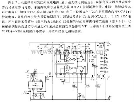
In Figure 8.7 is the sound infrared emitting circuit, which is used in wireless electric modulating station selectors, high-fidelity amplifiers and recorders, as the high sensitive sound equipment. The circuit is fixed with OTA as the modulating component. In the circuit, lower-frequency signal UE is delivered to the input point by capacitor of C1, and it is magnified to 2 times. By the potentiometer RP, the control current of OTA1 can be changed in a wide range, so that the magnifying parameter and modulation degree can be changed. The modulation signal is added to OTA2 by C6.
(View)
View full Circuit Diagram | Comments | Reading(592)
The pulse width modulation circuit
Published:2011/6/10 3:46:00 Author:Seven | Keyword: pulse width, modulation circuit
About the pulse width modulation circuit, we should first analyse the circuit. If the pulse is 3uS/5V, the normal state of Q4 is closed, and 3uS is conducting at the moment of starting to work. Therefore, Q5 is normally conducting, and closed in transiency. This seems no the same with what xbtxbt said. So after the initial analysis, the possible consequence is: 1.the working principle is wrong; 2. The circuit is drawn wrongly; 3.see as the figure, the input signal is input wrong.By the direction of diode D21, we guess that 3 may be right.Firstly, we assume that the 3 is right. (View)
View full Circuit Diagram | Comments | Reading(669)
| Pages:1769/2234 At 2017611762176317641765176617671768176917701771177217731774177517761777177817791780Under 20 |
Circuit Categories
power supply circuit
Amplifier Circuit
Basic Circuit
LED and Light Circuit
Sensor Circuit
Signal Processing
Electrical Equipment Circuit
Control Circuit
Remote Control Circuit
A/D-D/A Converter Circuit
Audio Circuit
Measuring and Test Circuit
Communication Circuit
Computer-Related Circuit
555 Circuit
Automotive Circuit
Repairing Circuit