
Circuit Diagram
Index 1776
555 two-tone electronic doorbell circuit (2)
Published:2011/6/7 5:16:00 Author:TaoXi | Keyword: 555, two-tone, electronic doorbell

As the figure 15-28 shows, the two-tone electronic doorbell uses the 555 as the core to form the multivibrator to drive the speaker. In fact the 555 is a voltage controllable oscillator, when you press AN, the C1 and C2 are charged respectively, the 555 starts working, the oscillation frequency f1=1.44/(R3+2R4)C1, when you loosen the AN, the oscillation frequency f2=1.44/(R2+R3+2R4)C1, the figure parameters's corresponding frequencies: the former is about 750Hz and the latter is about 500Hz.
At the same time, the C2 is index discharged through R1 and adds to the 555's control port pin-5 to change the standard comparison voltage of the internal substrate, so after you loosen the AN, the doorbell circuit outputs the tonal modification sound until the voltage of C2 is empty.
(View)
View full Circuit Diagram | Comments | Reading(2201)
Switching power supply of artificial circuit diagram
Published:2011/6/2 21:45:00 Author:Sophia | Keyword: Artificial circuit, Switching power supply
(View)
View full Circuit Diagram | Comments | Reading(818)
555 time control password electronic doorbell circuit
Published:2011/6/7 5:16:00 Author:TaoXi | Keyword: 555, time control, password, electronic doorbell
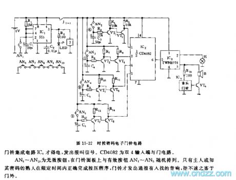
As the figure 15-22 shows, the doorbell is composed of the monostable timing circuit, the password switch, the NAND gate circuit and the sound circuit.etc. In the limited time, the circuit uses the program to press the password switch, the doorbell circuit sends out the alarm sound. If it exceeds the specified time or the password is wrong, there is no sound signal.
The timing switch circuit is composed of the IC1(555) and R1, C1, AN1, the timing time td=1.1R1C1, the figure parameter is 11 seconds. If you press AN1, the 555 will set, J and J1-1 contact point close to connect the power supply voltage of VT1~VT8,IC2,IC3.etc, the turn-on time is 11 seconds. The four groups of electronic switch is composed of the AN2~AN5,VT1~VT8.etc, the AN6~AN10 are the Invalid buttons.
(View)
View full Circuit Diagram | Comments | Reading(1444)
555 handheld simple money detector circuit
Published:2011/6/7 5:40:00 Author:TaoXi | Keyword: 555, handheld, simple, money detector
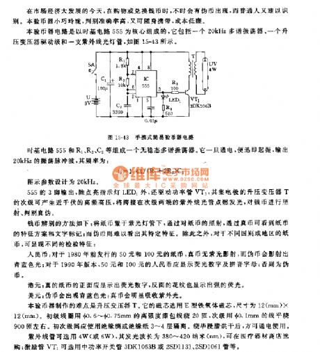
This money detector circuit uses the time base circuit 555 as the core, it is composed of a 20kHz multivibrator, a pressurization transformer driver stage and a ultraviolet light tube, as the figure 15-43 shows.
The astable multivibrator is composed of the time base circuit 555 and the R1, R2, C2.etc, it outputs the 20kHz oscillation pulse wave, the frequency fc=1.44/(R1+2R2)C3.
The output of 555's pin-3 turns on the LED1 and drives the power tube VT1, the collector electrode pressurization transformer T's secondary stage can produce the high frequency voltage of near 1000V to turns on the UV light.
The UV light can use the lamp of 4W or 6W, the wavelength is 380 to 420nm.
(View)
View full Circuit Diagram | Comments | Reading(1443)
555 time limiting lock alarm device circuit
Published:2011/6/7 6:43:00 Author:TaoXi | Keyword: 555, time limiting, lock, alarm device
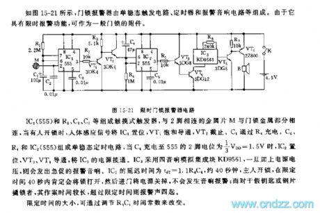
As the figure 15-21 shows, the door lock alarm device is composed of the monostable trigger circuit, the timer and the alarm sound circuit.etc. It has the function of time limit, so it can be used as the subsidiary part of the door lock.
The touch trigger is composed of the IC1(555) and R1, C1, C2.etc, the sequin M which is connected with pin-2 connects with the metal part of the door lock, when someone uses opens the lock, the human body sensor signal will set the IC1, Vt1 conducts and VT2 cuts off. C4 is charged through R4. The monostable timing circuit is composed of the C4, R4 and IC2(555), when C4 is charged to the 1/3VDD=1.5V, IC2 sets and VT3, VT4 conduct to open the IC3's power supply. IC3 uses the four stereo analog manifold KD9561.
(View)
View full Circuit Diagram | Comments | Reading(646)
the circuit of zero-delay RS-485 port
Published:2011/5/27 7:22:00 Author:Ariel Wang | Keyword: zero-delay, RS-485, port
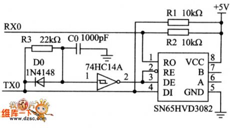
The circuit of zero-delay RS-485 port is as the chart below: (View)
View full Circuit Diagram | Comments | Reading(2746)
555 fish tank water temperature automatic heating control circuit
Published:2011/6/7 8:10:00 Author:TaoXi | Keyword: 555, fish tank, water temperature, automatic, heating control
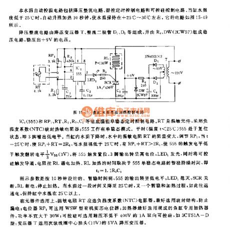
This fish tank water temperature automatic heating control circuit is composed of the step-down rectifier circuit, the humidity control timing circuit and the silicon-controlled rectifier control circuit. When the fish tank water temperature is lower than 25℃, the circuit automaticly heats for 10 seconds to keep the water temperature in the range of +25℃ to +30℃. The circuit is as shown in figure 15-49.
The step-down rectifier circuit is composed of the step-down transformer T, the rectifier diodes D1 and D2, and the voltage-stabilizing circuit which is composed of the R4 and DW outputs the +9V voltage.
The temperature control monostable timing circuit is composed of the IC1(555) and RP1, RT, R1, R2, C1. RT is the temperature sensitive component, it uses the negative temperature coefficient (NTC) glass sealing thermistor, the 555 works in the monostable mode.
(View)
View full Circuit Diagram | Comments | Reading(1256)
the circuit of ADS7824 parallel port
Published:2011/5/26 23:30:00 Author:Ariel Wang | Keyword: ADS7824, parallel port
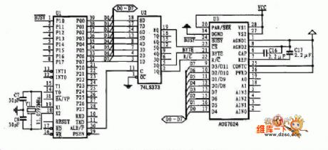
The circuit of ADS7824 parallel port is as below:
(View)
View full Circuit Diagram | Comments | Reading(610)
the circuit of MSM6822 applied
Published:2011/5/26 23:24:00 Author:Ariel Wang | Keyword: MSM6822 applied
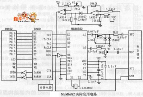
The circuit of MSM6822 applied is as below:
(View)
View full Circuit Diagram | Comments | Reading(592)
555 temperature limit controller circuit with heating acoustics alarming
Published:2011/6/3 9:03:00 Author:nelly | Keyword: temperature limit controller, heating acoustics alarming
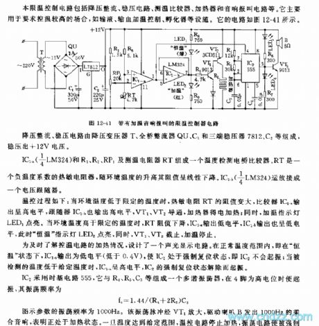
This temperature limit control circuit is made of hypotension rectifier, voltage-stabilizing circuit, temperature measurement comparator, heater and acoustics alarming circuit. It is mainly used in occasion which need higher controlled temperature, such asfluid infusion, blood transfusion heating control, incubator and so on. Its circuit is shown in the figure 12-41.
The process of temperature control is shown: when the ambient temperature is lower than the limited temperature, the resistance value of thermal resistor RT is greater, the output of comparator IC1-a is high level, the output of follower IC1-b is high level too, VT1, VT2 are turned on, the heater obtains electricity and is heated; at the same time, the heating indicator light LED1 turns on. When the ambient temperature is higher than the limited temperature, the resistance value of RT is decreased, IC1-a outputs low level, IC1-b outputs low level too, then the constant temperature indicator light LED2 turns on, at the same time, VT1, VT2 cut off, the heating is stopped.
(View)
View full Circuit Diagram | Comments | Reading(1056)
555 kitchen ventilator self controlled switch circuit
Published:2011/6/3 8:19:00 Author:nelly | Keyword: kitchen ventilator, self controlled switch
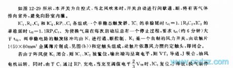
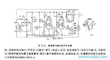
As shown in the figure 12-29, this switch is self-control, when the north wind blows, the switch can automatically turns on/off intermittently, the harmful gas will be discharged to outdoor, it avoids the gas filling into bedroom. If K1 is closed due to the wind, IC1, IC2 are set, the output terminal is high level, VT1 turns on, J pulls in, suction fan runs. At the same time, C3 is charged by RP1, when it is charged to 2/3 VDD of the threshold value level, IC2 is reset, J is discharged, the ventilator stops to running. If the wind power decreases, switch K1 cuts off, then IC1 automatically resets by td1. If the wind power does not decrease, K1 is still closed, then two monostable circuit trigger and set again, ventilator starts again. In other words, the on/off time of K1 is decided by the outside wind direction and the wind power. (View)
View full Circuit Diagram | Comments | Reading(634)
555 20-way answering device circuit
Published:2011/6/7 0:37:00 Author:nelly | Keyword: answering device
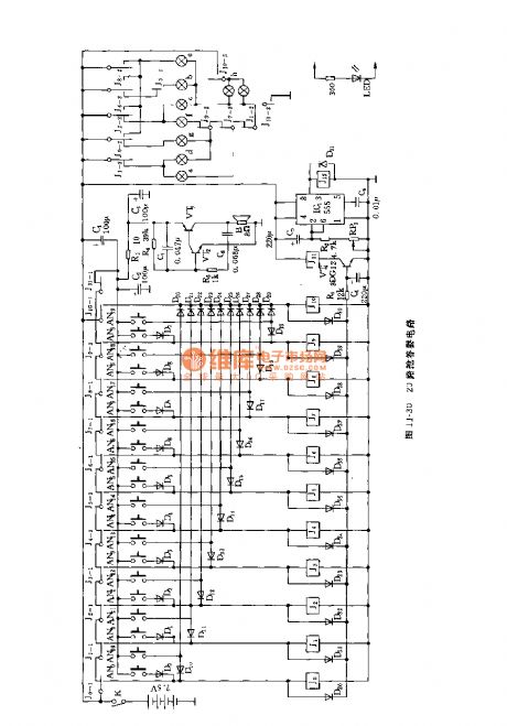
As shown in the figure 11-30, the answering device circuit contains 20-way answering device switch and relevant relay control circuit, combined display digital board, audio circuit and timing circuit. After the host bringing up the question, the responder hears the sound of answering device, then he can press the answering switch, the digital dispaly board shows the answering group number. Both the positive and negative of dispaly board will dispaly, the side which is face to the responder and audience is composed of nine branches of 6.3V/0.15A bulbs( 1 word is shown by two branches); the side which is face to the host is made of LED. Each LED is in series with a 300Ω resistor, it is used to limit current. For example, the 13 group presses AN13 first, then D13, D23 turn on,J3, J 10, J11 pull in, the current passes through the paragraphes of a, b, c, d, g, h, the bulb turns on, it displays word 13 . Due to J3 pulls in, the answering power supply is cut off.
(View)
View full Circuit Diagram | Comments | Reading(699)
555 simple toy electronic organ circuit
Published:2011/6/3 19:51:00 Author:nelly | Keyword: toy electronic organ
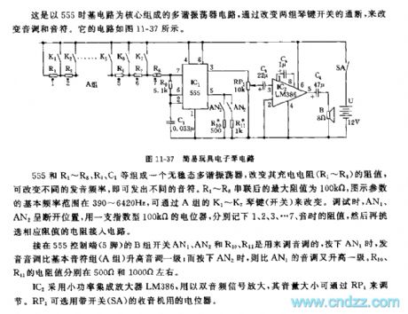
This multivibrator circuit is composed as the core of 555 time base circuit, the tone and musical note is changed by changing the on/off of the two groups of piano keyboard switch. The circuit is shown in the figure 11-37.
The actable multivibrator is made of 555 and R1~R8, R9, C1, the different pronouncing frequency can be changed by changing the resistance of charge resistance, then it will emit different musical note. After R1~R8 are connected in series, the max resistance is 100kΩ, the basic frequency of graphical parameters are between 390~6420Hz, they are decided by A group's K1~K7 piano keyboard switch. When it is debugging, AN1, AN2 are off, a 100kΩ exponential type potentiometer is used to take down the resistance when the tone is 1, 2, 3...7, then relevent resistor is selected to connect into the circuit.
(View)
View full Circuit Diagram | Comments | Reading(2285)
555 static low power dual tone door flute circuit
Published:2011/6/3 8:44:00 Author:nelly | Keyword: static, lower power, dual tone,
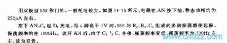
Generally, the power consumption is large by taking the bipolar 555 as the doorbell. As shown on the figure 11-15, the circuit's static power is about 250µA before the AN is turned on. Turn on the AN, C2 will be charged by the D2. When the four foot is larger than 1v, the multivibrator which consists of 555 and R2, R3, C4 will be onset. The oscillation frequency is about 1000Hz. Turn off the AN, the oscillation frequency will be lower because the C5 and C4 is parallel connecting. It's about 700Hz, so we call it dual tone (View)
View full Circuit Diagram | Comments | Reading(728)
555 digital timer circuit used in competition
Published:2011/6/3 20:14:00 Author:nelly | Keyword: digital timer, competition
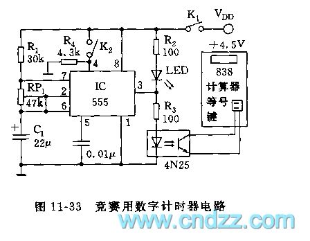
As shown in the figure 11-33, the timing circuit still uses inexpensive 838 calculator as display terminal, it is composed of second clock generator and photocoupler. It can be used in counting second occasions such as sports tournament, intelligence competition, the reading is accurate and visualized, it also has suspensive function.
The actable multivibrator is made of IC(555) and R1, RP1, C1, the oscillation frequency is f=1.443/(R1+RP1)C1, the frequency can be adjusted to 1Hz by RP1. K1, K2 are closed, then IC starts to vibrate. The 3 foot output is added to photocoupler, the isolated output is added to = key of 838 calculator. Before timing, it should operate calculator firstly, it is counted for accumulating 1, in other words, pressing ON/C key → + key → 1 key, then K1, K2 are turned on.
(View)
View full Circuit Diagram | Comments | Reading(1350)
555 multi-analogue sound generator circuit
Published:2011/6/7 4:23:00 Author:nelly | Keyword: multi-analogue sound, generator
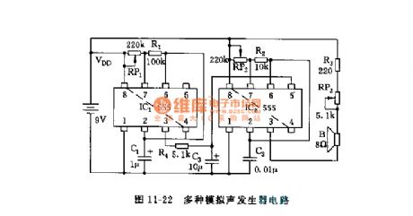
As shown in the figure 11-22, the circuit is composed of two 555 and some resistor capacitor components, the astable multivibrator connsists of IC1 and RP1, R1, C1, the oscillation frequency is about 5~10Hz, it can be changed by adjusting RP1. The frequency of oscillator which is made of IC2 and RP2, R2, C2 is between 1~10kHz, it can be changed by adjusting RP2, IC2 is a controlable voltage oscillator, its control terminal 5 foot is controlled by triangular wave voltage, this triangular wave is obtained from IC1 output and then integrated by R4, C3 integration circuit. IC2's oscillation frequency changes in relation to control voltage, it will send out all kinds of analogue sound, such as cricket noise and bird sound.
(View)
View full Circuit Diagram | Comments | Reading(1338)
555 Nintendo game timer circuit
Published:2011/6/4 6:06:00 Author:nelly | Keyword: Nintendo, timer
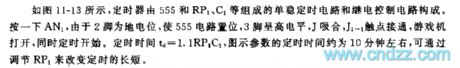
As shown on the figure 11-13, the timer consists of relay control circuit and monostable timing circuit which is made up of 555, RP1 and C1. Turning on the AN1, the 555 circuit will be onset because the 2 foot is the ground potential, the 3 foot is high power level, the J is pull-in. The J1-1's contact will be on-state, the game opens and starts together. The timing time: td=1.1RP1C1. The timing time is about 10 minutes. It can use RP1 to change the time.
(View)
View full Circuit Diagram | Comments | Reading(707)
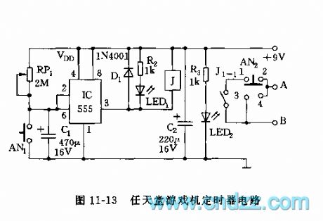
555 60s acousto-optic digital timer circuit used in competition
Published:2011/6/3 20:31:00 Author:nelly | Keyword: acousto-optic digital timer
The monostable timing circuit is composed of IC1(555) and RP1, R1, C1, the monostable short stabilization time td=1.1(R1+RP1)C1, it is fixed on 60s by adjusting RP1. Pressing AN, the timing is starting.
The second signal oscillator is made of IC2 and R2, RP2, C2, the oscillation frequency is f=1.44/(R2+RP2)C2, the frequency can be 1Hz by adjusting RP2. With about 1300Hz frequency, the audio frequency oscillator consists of IC3 and R4, R5, C3, its reset terminal is controlled by IC2's output, when it sends out a second pulse signal, it will emit do sound, LED lights. After timing, IC2's 3 foot turns into low level, then IC3 is in enforced reset state, it stops to vibrate.
(View)
View full Circuit Diagram | Comments | Reading(732)
555 optical control delay flash toy car circuit
Published:2011/6/7 7:22:00 Author:nelly | Keyword: optical control, delay flash, toy car

After receiving the optical signal, this car will move straight forward, at the same time, it has red and green alternately flashing. After one minute, it stops automatically.
As shown in the figure 11-4, silicon photocell adopts 2CR33 type, after illuminated, VT1 is saturation conduction, IC1 is triggered, 3 foot is high level, VT2 turns on, J pulls in, J1-1 turns on, DC motor M operates, the car moves. IC1 is monostable delay circuit, the delay time also is the car's running time td=1.1R4C3, it is about 60s. When it is time out, 3 foot turns to low level, J releases, motor M stops running. IC1 triggers setting, simultaneously, VT3 turns on, the multivibrator which is composed of VT4, VT5 starts to vibrate, it sends out the signal of red and green alternately flashing, the period is 2s.
(View)
View full Circuit Diagram | Comments | Reading(767)
555 firing control circuit
Published:2011/6/7 7:41:00 Author:nelly | Keyword: firing control
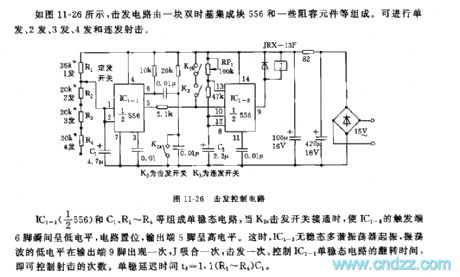
As shown in the figure 11-26, the firing circuit is composed of a double time base integrated block 556 and some resistor capacitor components. It can make single shot, 2 shots, 3 shots, 4 shots and a running fire.
The monostable circuit is made of IC1-1(1/2 556) and C1, R1~R4, when K2 fires switch to turn on, the trigger terminal 6 foot of IC1-1 turns to low level at the moment, the circuit is set, output terminal 5 foot is high level. Then IC1-2 astable multivibrator starts to vibrate, the low level of oscillatory wave turns one time in the output terminal 9 foot, J pulls in one time, J also fires one time. The frequency of shoot can be controlled by the reversal time of IC1-1 monostable circuit. The monostable delay time td=1.1(R1~R4)C1.
(View)
View full Circuit Diagram | Comments | Reading(1023)
| Pages:1776/2234 At 2017611762176317641765176617671768176917701771177217731774177517761777177817791780Under 20 |
Circuit Categories
power supply circuit
Amplifier Circuit
Basic Circuit
LED and Light Circuit
Sensor Circuit
Signal Processing
Electrical Equipment Circuit
Control Circuit
Remote Control Circuit
A/D-D/A Converter Circuit
Audio Circuit
Measuring and Test Circuit
Communication Circuit
Computer-Related Circuit
555 Circuit
Automotive Circuit
Repairing Circuit