
Circuit Diagram
Index 1773
TDA381—the integrated circuit of the SRS stereo effect process
Published:2011/6/10 0:57:00 Author:qqtang | Keyword: integrated circuit, SRS stereo
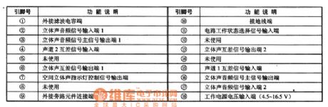
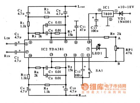
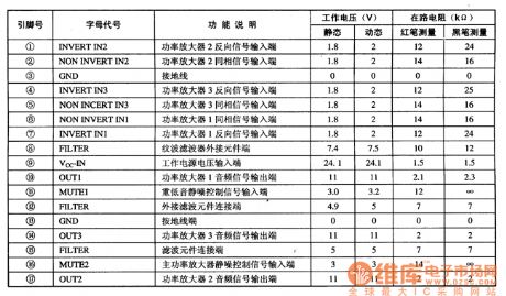
TDA381 is an integrated circuit of the SRS stereo effect process produced by Philips, which is widely used in all kinds of stereo systems.1.function featuresTDA381 can switch the single channel signal into the analog stereo sound signal, which works in the conducting state of the stereo channel, and it can also work in the space stereo sound state.2.pin functions and dataTDA381 is in 18-pin dual in-line package, whose pin functions are listed in Table 1.Table 1. Pin functions of TDA381
Figure 1. The typical application circuit of TDA381
(View)
View full Circuit Diagram | Comments | Reading(1527)
TC9308AF-029--the system control microcomputer integrated circuit
Published:2011/6/10 0:57:00 Author:qqtang | Keyword: system control, integrated circuit
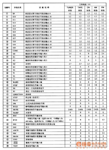
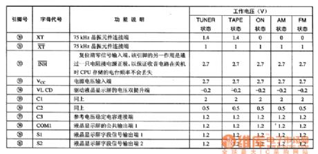
TC9308AF-029 is a system control microcomputer integrated circuit produced by Toshiba, which is widely used in walkmen and function control, such as Aiwa, Sanyo and Toshiba, etc.1.function featuresTC9308AF-029 contains the CPU, clock oscillating circuit, key pulse counter, preset frequency distributor, reset control circuit, wave control circuit, reproduce control circuit, recording control circuit, system and LCD display decoding drive circuit, etc.2.pin functions and data
(View)
View full Circuit Diagram | Comments | Reading(838)
The LEV tester circuit of voltage comparator LM324
Published:2011/6/10 0:58:00 Author:qqtang | Keyword: tester circuit, voltage comparator
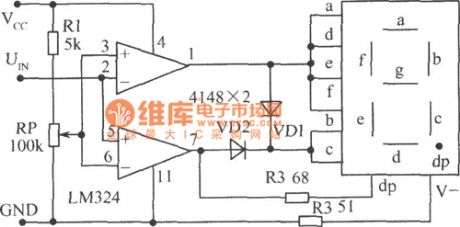
In the figure is the LEV tester circuit of voltage comparator LM324, whose character is that it's convenient for the threshold value LEV adjustment, and it can test the logic LEV of DTL, TTL, CMOS and so on. Judging from the voltage comparator, we know when the input(positive) pole voltage is higher than that of the opposite(negative) pole, the comparator outputs a high LEV, and vice versa. RP is a comparing voltage adjusting potentiometer, when UIN is higher than the set voltage, 7-pin outputs a high LEV, and it indicates 1 , the decimal dp is glowing simultaneously. (View)
View full Circuit Diagram | Comments | Reading(2509)
The sickroom patient alarm screen circuit
Published:2011/6/10 1:00:00 Author:qqtang | Keyword: sickroom, alarm screen circuit
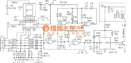
In the figure is a sickroom patient alarm screen circuit, whose acousto-optic terminal is installed in the nurse duty room. 1 bit number is displayed, and every 3 beds share a number, so a total of 27 patients are covered, which can meet the need of a small hospital. This circuit is only made of a common micro-power CMOS circuit IC1(4511) and IC2(4001), and a ding-dong door bell chip IC3(KD-1543). It is not only low-cost, which consumes only several microampere of power in waiting state, it is powered with two No.5 batteries (6v), but also doesn't need to install a power supply switch, so the users don't need to worry about about the power failure of the grid.
(View)
View full Circuit Diagram | Comments | Reading(664)
The relationship circuit diagram betweent frequency band and capacitance capacity
Published:2011/6/9 22:38:00 Author:Sophia | Keyword: Frequency band, Capacitance capacity
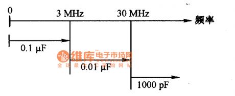
The diagram shows that the capacitance should be adopted with different capacitance, the capacitor should adopt ceramic capacitor with excellent frequency characteristic.
(View)
View full Circuit Diagram | Comments | Reading(606)
TA8218AH--the 3 channel audio power amplifier integrated circuit
Published:2011/6/9 21:02:00 Author:qqtang | Keyword: audio power amplifier, integrated circuit

TA8218AH is the 3 channel audio power amplifier integrated circuit, produced by Toshiba, which is widely used in the multimedia stereo, domestic stereo, car stereo and TV stereo, etc.1.functions featuresTA8218AH contains 3 lines of same-function audio power amplifier circuits, and it also has functions of silence/mute protection and over heat/voltage protection, etc.2. Pin functions and dataTA8218AH is in 17-pine package, whose pin functions and data are listed in table 1.Table 1. Pin functions and data of TA8218AH
(View)
View full Circuit Diagram | Comments | Reading(4031)
TA8132--the single chip reception integrated circuit
Published:2011/6/9 20:50:00 Author:qqtang | Keyword: single chip, integrated circuit
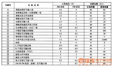
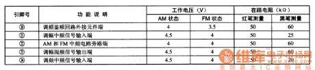
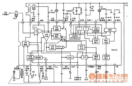
1.function featuresTA8132 contains AM mixing, AGC, INTREQ and detection circuit; it also contains FM INTREQ, frequency discrimination and stereo circuit. In addition, it has the functions as follows. FM/AM output point(9-pin) can provide with auto stop signal of counting modulation for the digital channel selecting modulation system. AM INTREQ counting frequency is 465KHZ; and the FM INTREQ counting frequency can be 10.7MHz, and according to the need, it can be replaced by 1.3375MHz by starting the 1/8 distribution circuit of IC .2.pin functions and data
(View)
View full Circuit Diagram | Comments | Reading(1223)
TA8122AN and TA8122AF--the single chip reception integrated circuit
Published:2011/6/9 20:51:00 Author:qqtang | Keyword: single chip, integrated circuit
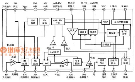
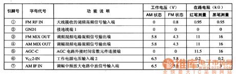
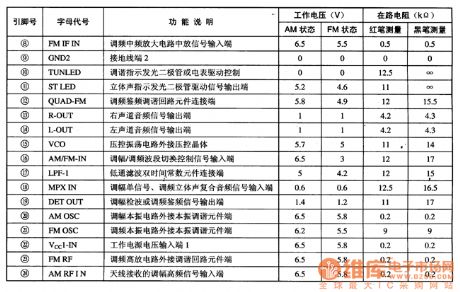
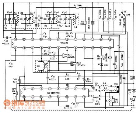
TA8122AN/AF is the single chip reception integrated circuit produced by Toshiba, which is used in all kinds of stereo reproducing circuits, such as car stereo and domestic stereos, etc.1.function featuresTA8122AN/AF contains AM modulation mixing, self-oscillation, INTREQ, detection circuit; FM AGC, mixing, self-oscillating, INTREQ, detection, stereo decoding circuit, etc; the additional circuits includes the display drive circuit, stereo ordering drive circuit, AM/FM shifting electric switch circuit, etc. The internal circuit of TA8122AN/AF is shown in Figure 1.
(View)
View full Circuit Diagram | Comments | Reading(3782)
The playback single chip integrated circuit
Published:2011/6/9 21:00:00 Author:qqtang | Keyword: single chip, integrated circuit
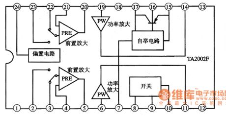
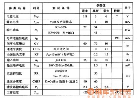
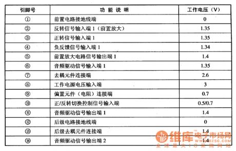
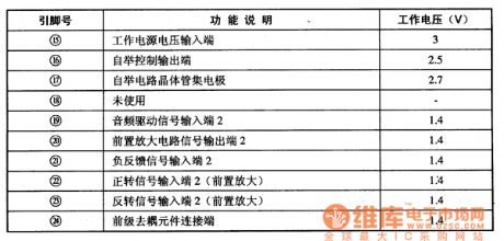
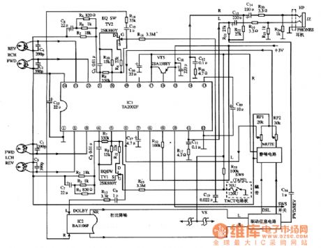
TA2002F is theplayback single chip integrated circuit produced by Toshiba, which is widely used in Aiwa and Toshiba walkmen.1.function featuresTA2002F contains the bias circuit and two teams of separated pre-amplifier, tape forward/backward shifting electric switches, two teams of post-stage amplifier, tape type selecting and wave filtering circuits, etc. Its internal circuit are shown in Figure 1.Figure1 the internal circuit of TA2002F2. Main feature parametersMain feature parameters of TA2002F are listed in table 1.
(View)
View full Circuit Diagram | Comments | Reading(1139)
The 8-bit LED dynamic display circuit of ICM7218A
Published:2011/6/10 3:53:00 Author:qqtang | Keyword: LED dynamic display, 8-bit
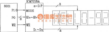
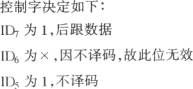
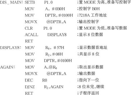
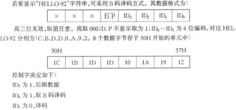
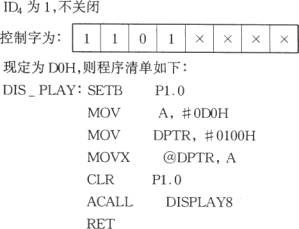
The 8-bit LED dynamic display circuit of ICM7218AIn the figure is the 8-bit LED hardware scanning dynamic displayer consisting of 8031 and ICM7218A. As ICM7218A has functions of both software decoding and hardware decoding, so there two ways to make the displayer indicate HELLO-92 , which are software decoding and hardware decoding. The following will introduce them respectively.The software decoding programmingFirstly, find out the code of the letters that need to indicate. According to the corresponding relationship between a,b ,c,d,e,f,g and data bit, we can get that in H, a and d are 0, the others are l, i.e 10111110 or BEH.
(View)
View full Circuit Diagram | Comments | Reading(1136)
The digital display calendar clock circuit
Published:2011/6/10 3:54:00 Author:qqtang | Keyword: calendar clock
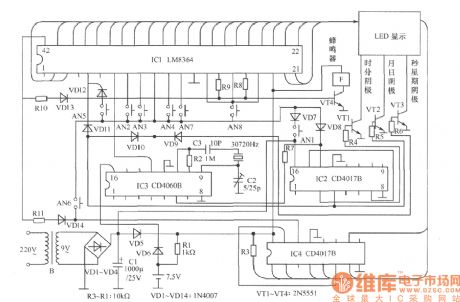
The circuit can display month, date, hour, minute, second and week, and they can be automatically switched, and it can ring for 2 times, it also has functions of sleep timing function in 59min. The calendar clock is punctual, easily adjusted, clear at night and easily made.Working principleThe core of the circuit is a PMOS mass integrated circuit LM8364. 4-pin is the selective terminal of 12/24 h, and the high LEV is 24h system. When 6-pin is suspended, the 60Hz time based signals are input from 7-pin, and when receiving the high LEV, the 50Hz time based signal should be input from 7-pin. (View)
View full Circuit Diagram | Comments | Reading(3526)
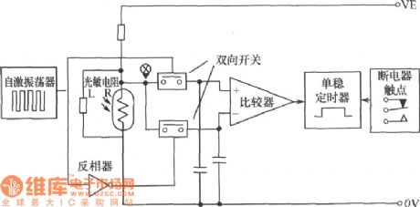
Photosensitive diode type photoelectric coupler circuit
Published:2011/6/8 22:09:00 Author:Christina | Keyword: Photosensitive diode, photoelectric coupler
The appearance and circuit of the photosensitive diode type photoelectric coupler is as shown in the figure.
Figure: The appearance and circuit of the photosensitive diode type photoelectric coupler (View)
View full Circuit Diagram | Comments | Reading(606)
OM5234-FBP-536 and OM5234-FBP-522--the system control microcomputer integrated circuit
Published:2011/6/10 1:01:00 Author:qqtang | Keyword: system control microcomputer, integrated circuit
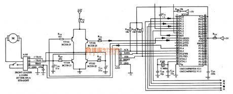
OM5234-FBP-536 and OM5234-FBP-522 are the system control microcomputer integrated circuits, which are widely used in all kinds of disc players.1. Function featuresOM5234-FBP-536 and OM5234-FBP-522 have almost the same functions, only some parameters are different, but they can replace each other. They contains the serial number and clock process circuit, clock oscillating circuit and other control functions circuits, etc.2.pin functions and dataOM5234-FBP-536 is in 40-pin dual in-line package, whose pin functions and data are listed in the figure.
(View)
View full Circuit Diagram | Comments | Reading(661)
Christmas fancy Lantern Circuit Of Photo-coupler
Published:2011/5/11 4:57:00 Author:chopper | Keyword: Photo-coupler, Christmass fancy Lantern
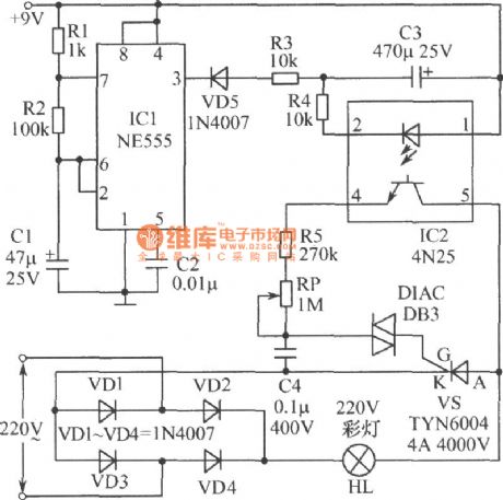
As shown in figure is an attractive Christmas fancy lantern.When the power source is available,lantern HL will brighten gradually;and it will darken automatically when it reaches the brightest level.This process is smooth.The luminance fluctuation of lantern HL depends on the charging and discharge of capacitor C3.When the output of IC1's 3 feet is high-level,capacitor C3 will discharge.And the luminance of lantern HL will decrease through photoelectric isolation of IC2(CN25).IC1 here acts as a astable oscillator,and its frequency is made by R1、R2 and C1. (View)
View full Circuit Diagram | Comments | Reading(1122)
Digit Counter Circuit
Published:2011/5/11 5:00:00 Author:chopper | Keyword: Digit Counter
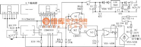
As shown in figure,the original mechanical counterjust has two magnetic switch signals terminals, while electronic counter increases input terminal c,d of AC6.3V,and thereare 4 binding posts. C1,C2,VD1,VD2 form voltage-multiplying circuit,filter circuit,and output 5V stable DC voltage after voltage stabilization,and become about 3.6V DC voltage after voltage reduction by VD3,VD4.E1 is a small Ni-cd rechargeable battery.When the mains supply is available,the supply will charge E1;and when the supply stops,E1 will charge the load to maintain the value of the counter.VD3 and VD4 here have an effect of insulation. When input magnetic switch at the both end of a,b closes,the AC 220V voltage is connected.The voltage will be converted into AC pulsating voltage after it is reduced by R1~R4 and bridgedioded by VD5~VD8.And the AC pulsating voltage provides luminotron of the photo-coupler with voltage after it is limited by R5 to make luminotron glow. The resistance of photosensitive tube will decrease because of light and generate a decline pulse,which will reverse direction through N3.And the pulse offers power to trigger of N1,N2 and N1 will output count pulse. N1,N2,N3 constitute pulse shaping circuit together. (View)
View full Circuit Diagram | Comments | Reading(1350)
High sensitivity alarm circuit
Published:2011/6/9 2:19:00 Author:Christina | Keyword: High sensitivity, alarm
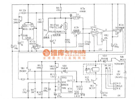
The high sensitivity alarm circuit is as shown in the figure, the photoconductive resistance LDR is connected with three ordinary resistances.
The alarm sensor circuit is as shown in the figure. In this circuit, the half of the CMOS integrated timer 7556 is connected as the self-excited oscillator, the IC2c constitutes the equivalent inverter, the oscillator is under the function of IC2c to complete the alternate connection. The IC2a and IC2b are the two-node switch. The input impedance if the IC2's control pin is very high, so the load is very light for the IC1a, the voltage dividing network is composed of the R3, R4, R5, R6, the photoconductive resistance and the LDR, this makes the X point has the required potential to charge the C4 and C5 through the double node switch.
(View)
View full Circuit Diagram | Comments | Reading(794)
Steady operation circuit diagram
Published:2011/6/8 23:00:00 Author:Sophia | Keyword: Steady operation

(View)
View full Circuit Diagram | Comments | Reading(655)
VOUT terminal protection circuit diagram
Published:2011/6/8 21:55:00 Author:Sophia | Keyword: VOUT terminal, Protection circuit
(View)
View full Circuit Diagram | Comments | Reading(810)
Input protection circuit of high input impedance circuit diagram
Published:2011/6/8 21:41:00 Author:Sophia | Keyword: High input impedance circuit, Input protection circuit
(View)
View full Circuit Diagram | Comments | Reading(772)
Welder no-load power saver circuit diagarm 10
Published:2011/6/10 3:50:00 Author:Lucas | Keyword: Welder, no-load , power saver
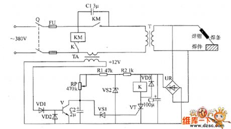
The welder no-load power saver circuit is composed of the detection circuit and power saving control circuit, and the circuit is shown as the chart. Detection circuit is composed of the current transformer TA, diodes VD1, YD2, transistor V, bridge rectifier UR, filter capacitor C3. Power saving control circuit consists of resistors R1, R2, capacitors C1, C2, voltage regulator diodes VS1, VS2, thyristor VT, diode VD3, relay K and AC contactor KM. R1, R2 select 1/2W metal film resistors. RP uses 2W organic solid potentiometer. C1 uses the CBB capacitor or oil capacitor with the voltage being 630V. VD1 ~ VD3 select 1N4007 silicon rectifier diodes. VS1 uses ZCW15 silicon voltage regulator diode.
(View)
View full Circuit Diagram | Comments | Reading(1933)
| Pages:1773/2234 At 2017611762176317641765176617671768176917701771177217731774177517761777177817791780Under 20 |
Circuit Categories
power supply circuit
Amplifier Circuit
Basic Circuit
LED and Light Circuit
Sensor Circuit
Signal Processing
Electrical Equipment Circuit
Control Circuit
Remote Control Circuit
A/D-D/A Converter Circuit
Audio Circuit
Measuring and Test Circuit
Communication Circuit
Computer-Related Circuit
555 Circuit
Automotive Circuit
Repairing Circuit