
Circuit Diagram
Index 1766
The component detection circuit of Daewoo ESPERO igniting system
Published:2011/5/18 22:18:00 Author:Borg | Keyword: detection circuit, Daewoo ESPERO, igniting system
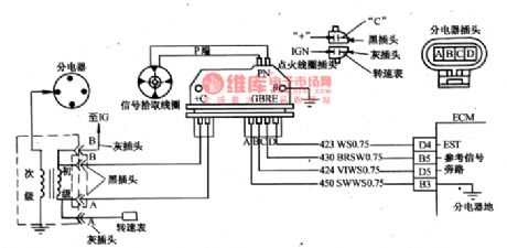
Both the high voltage wires of *1 and *2 should be checked to make sure that the wire of spark piston is connecting. If sparks come out when EST plug(wire 4) is being pull off, that means the output voltage of signal picking coil is too low to make EST work. If *3 has sparks, that means the problem is in electricity distributor and spark distributor. When the *4 is in normal condition, there should be battery voltage on both terminals c and + of igniting module, and the voltage is tend to be low, that mean there are breaks or resistance value is too high between distributor and igniting coil or switch.
(View)
View full Circuit Diagram | Comments | Reading(2019)
The working computer control system detection circuit of Santana 2000GLi
Published:2011/6/10 1:40:00 Author:Borg | Keyword: control system, detection circuit
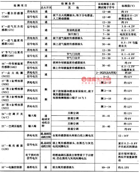
To do detection on working computers and sensors, the wires should be turned off first. Therefore, we should shut down the igniting switch, and connect the detection box and connecting cables with computer controller, then dothe detection refering to Table 1.
(View)
View full Circuit Diagram | Comments | Reading(583)
The wiper-washer circuit of Buick-Century
Published:2011/5/26 22:02:00 Author:Borg | Keyword: wiper-washer circuit, Buick-Century
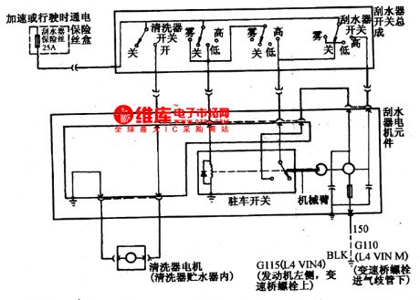
Washer pump is controlled by a independent switch. The wiper has 4 gears of fog, off, low and high in total. When it is at the fog gear, the current comes from wiper fuse(25A), in the meantime, the relay in the P switch acquires the current and makes the terminals pull in, then the current goes into the motor, and the motor run for a course at a low speed, in which the course in interrupted. If therelay didn't pull in, the motor wouldn't work normally. In the Figure, there is no the electric delaying display circuit.
(View)
View full Circuit Diagram | Comments | Reading(666)
The fault diagnosis circuit of Daewoo-ESPERO fuel pump relay
Published:2011/5/18 22:22:00 Author:Borg | Keyword: fault diagnosis circuit, Daewoo-ESPERO
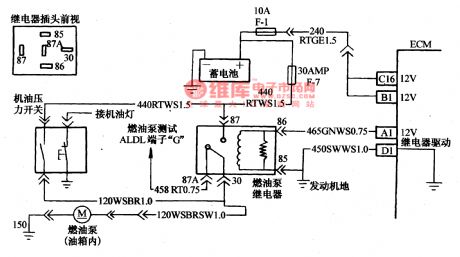
When the igniting switch is at the ON gear, computer ECM will start the fuel pump relay and run the pump in the oil box. When the engine starts or runs, if ECM receives the igniting reference pulse signal, the fuel pump will go on to work; if there is no reference pulse signal, then the ECM will shut down the pump in 2 secondsafter the igniting switch is on.
It will lead to a long starting time of the engine if the oil pump relay doesn't work, especially when the temperature of the engine is low or the engine oil viscosity is high.
(View)
View full Circuit Diagram | Comments | Reading(2055)
AN8813NSBS-the integrated 4-channel drive circuit
Published:2011/5/18 22:20:00 Author:Borg | Keyword: integrated, 4-channel, drive circuit
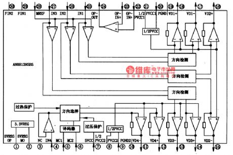

AN8813NSBS is an integrated 4-channel laser head drive circuit which is produced by Panasonic specially for DVD core. It is widely used in Panasonic DVD players.1.function featuresAN8813NSBS can convert loading control signals and servo control signals of focusing, tracking and feeding into drive voltage, by which is can load motors, feed motors, focus and track coils. The internal circuit of it is as shown in Figure 1.
2.pin functionsAN8813NSBS is in flat 30-lead package, whose pin functions are listed in Table 1.
(View)
View full Circuit Diagram | Comments | Reading(551)
Buick Century lighting and singal circuit diagram(2)
Published:2011/5/16 3:40:00 Author:Nicole | Keyword: Buick Century, lighting, singal
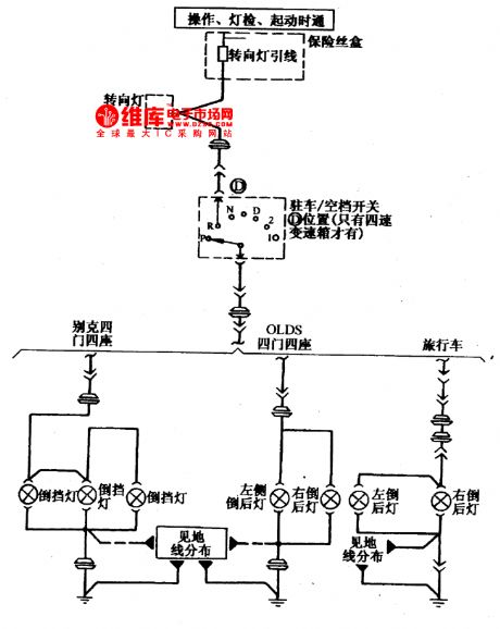
Buick Century car reversing lamp circuit diagram(2) (View)
View full Circuit Diagram | Comments | Reading(455)
Buick Century lighting and singal circuit diagram(1)
Published:2011/5/16 3:42:00 Author:Nicole | Keyword: Buick Century, lighting, singal
Buick Century car steering signal and danger signal, parking lamp circuit diagram(1) (View)
View full Circuit Diagram | Comments | Reading(514)
The electric control circuit of Buick-Century engine and auto transmission(3)
Published:2011/5/18 23:53:00 Author:Borg | Keyword: control circuit, Buick-Century
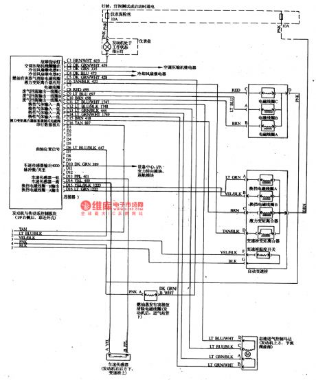
The control modules of the engine and transmission are also the interfaces of C and D, of which C has 16 terminals, and 15 of them are in use, most of them connect to some executors, such as fault indicator, the magnetic clutch of air-conditioning compressor, cooling fans of 1# and 2#, active carbon jar, liquid torque converter, waste recycle control valve, idling speed control valve( in the figure, it is misinterpreted as inert gas) and series data slides, etc.
The auto transmission system circuit of Buick-Century engine(3.1) (3) (View)
View full Circuit Diagram | Comments | Reading(774)
The electric control circuit of Buick-Century engine and auto transmission
Published:2011/5/18 23:57:00 Author:Borg | Keyword: control circuit, Buick-Century
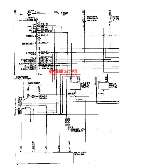
The control computer of the engine and transmission system is fixed behind the I/p, near the cover and close to the shell, on which there are 6 interfaces of A,B,C,D,C and D:7 of 12 terminals of interface A are in use, which mainly connect to the igniting switch, battery and crankshaft position sensor, the standard voltage is 5V; interface B also has 12 terminals , and 9 of them are in use, most of them connect with sensors of the throttle, air-conditioning, admission temperature, coolant temperature and explosive, etc.
(View)
View full Circuit Diagram | Comments | Reading(789)
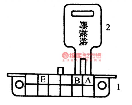
The flash sequence of the Daewoo fault code of 12
Published:2011/5/19 21:46:00 Author:Borg | Keyword: flash sequence, Daewoo
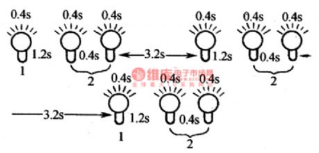
Flashing code reading: if the igniting switch is on but the engine is not running, connect the diagnosis plug with the ground, then the code can be got by flashing the fast repairing motor indicator. The character of the flashing sequence are: SES is on for 0.4s,SES is off,SES is off for 0.4s; the digital interval is 1.2s; code interval is 3.2s. The the flashing sequence of the normal code of 12 is seen in Figure 10.
The sequence of fault codes:The 10 bit number flash whose interval is 0.4sBreak for 1.2sThe 1 bit number whose interval is 0.4s.
(View)
View full Circuit Diagram | Comments | Reading(730)
ShenLI electromotor half wave speed adjustment circuit
Published:2011/5/19 0:41:00 Author:TaoXi | Keyword: ShenLI, electromotor, half wave, speed adjustment
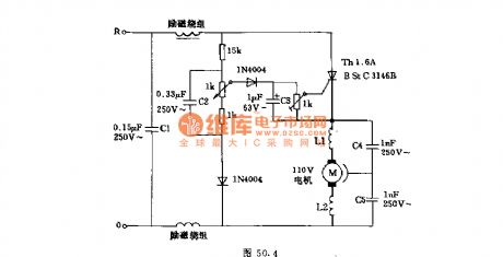
The circuit can be used to adjust the speed of the ShenLI electromotor or the single-phase asynchronous motor, it is the half-wave controlled rectifier circuit. When there is no load, the armature has high EMF, so that at the end of the half cycle, the thyristor is triggered immediately. When there is load, the armature's voltage reduces, the thyristor will be triggered in the rising voltage part. The L1, L2 and the capacitances C4 and C5 can be used to resist the interference.
(View)
View full Circuit Diagram | Comments | Reading(992)
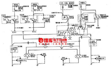
The fault self-diagnosis circuit of Tianjin Xiali TJ710OE
Published:2011/5/26 22:03:00 Author:Borg | Keyword: fault self-diagnosis circuit, Tianjin Xiali
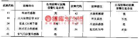
There is a self-diagnosis and self-protection measure in Xiali EFI system, and there is a fault diagnosis alarm lamp on the combination instrument, when the car is starting,the lamp will light, if the system is normal, the lamp will be off when the car has been started. If the e-control system sensor and igniting signal are malfunctioning, the fault alarm lamp light, however, it won't light when the CO content adjuster switch system and starting signal are malfunctioning.
(View)
View full Circuit Diagram | Comments | Reading(605)
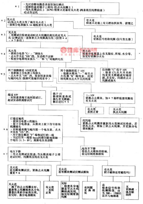
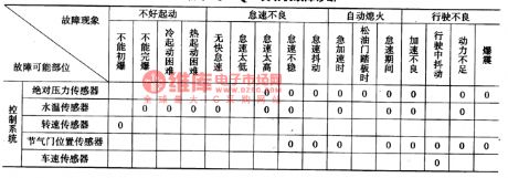
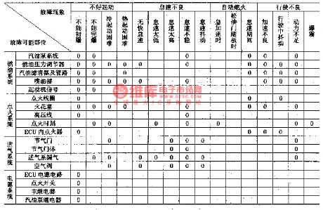
The diagnosis and repairing circuit of common fault of Daewoo-ESPERO
Published:2011/5/19 21:28:00 Author:Borg | Keyword: common fault, Daewoo-ESPERO
1.Introduction It should be in accordance with circuits when doing tests on oil injection control system, and on the basis of exact observation and practice, only after further analysis and integration can we find reliable methods. If the fast repairing motor indicator is on all the time, before we get down to solving the problem, we should ask the driver about the cause. If the engine rotates but not runs, we can solve the problem by the fault judging course in the following descripiton.
(View)
View full Circuit Diagram | Comments | Reading(662)
The oil pump control system circuit of Tianjin Xiali TJ710OE
Published:2011/5/26 22:04:00 Author:Borg | Keyword: oil pump, control system, Tianjin Xiali
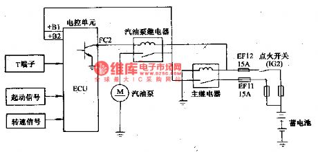
When the igniterisat the starting gear, or the in 2s after the engine crankshaft steering signals are delivered to ECU, then ECU will connect the oil pump relay terminals FC2 with the ground connection and the oil pump gets into working. This will make sure the oil pump runs only under the condition that the engine is working, therefore, power consumption and friction are diminished. See as the figure: the oil pump control system circuit
(View)
View full Circuit Diagram | Comments | Reading(489)
AN7120 2.lW-the integrated circuit of audio power amplifier
Published:2011/5/19 21:31:00 Author:Borg | Keyword: integrated circuit, audio power amplifier
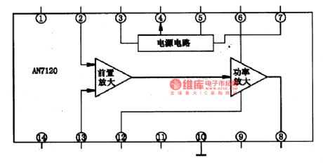
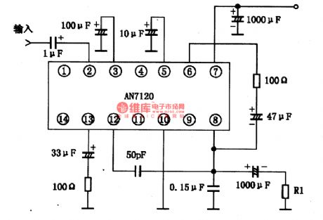
AN7120 is a integrated line circuit of 2.lW audio power amplifier which is produced by Panasonic. It is used in radios, recorders, record-players and computer stereos as the output stage.1.The internal circuit and pin functions AN7120 characterizes with low working voltage, large output power, trivial AC distortion, low engine starting noise and stable work even when the power supply is sharply changing. The pin of ④ can output stable voltage for pre-stage or something out of the circuit. The IC is in 14-lead dual in-line package.
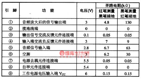
Table 1 pin functions and data of AN7120
(View)
View full Circuit Diagram | Comments | Reading(962)
AN711O,AN711OEl.2W-the integrated circuit of audio power amplifier
Published:2011/5/19 21:32:00 Author:Borg | Keyword: integrated circuit, audio power amplifier
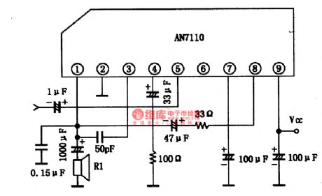
1.the internal circuit and pin functions of AN711O/EThe internal equivalent circuit of AN711O/E is shown in Figure 1, the IC is in 9-lead single in-line package, and the pin functions and data are listed in Table 1.
Figure 1 the internal equivalent circuit of AN711O
2.principle parameters of AN711O(1) Limiting parameter. Power supply voltage Vcc=18V,power supply current Icc=2A,Power consumption PD=1.5W.(2)principle parametersWhen Vcc=9V,RL=8Ω,f=1KHz,Ta=25℃, there are the following parameters.3.the typical application circuit of AN711OThe typical application of AN711O/E is shown in Figure 2.
(View)
View full Circuit Diagram | Comments | Reading(809)
The power supply and igniting system circuit of Tanjin Xiali TJ7100 and 7100U
Published:2011/5/26 22:04:00 Author:Borg | Keyword: power supply, igniting system, Tanjin Xiali
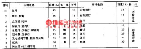
Xiali 12V electric system is single-line, negative ground connection, the model of the battery is 6-QA-45. There is a thick wire on it's positive point connecting with the stater, and another 3 linking to a connector, and the fuses of a,b and c divide the circuit into 3, see as Figure 1 to Figure 3.Fuse a , specification is 0.85mm, volume 60A. It links to the fire wire of the AC motor, igniting switch (27), brake lamp (24), interior lamp(25), clock(43), width lamp (57 and 59) and instrument light(61),etc.Fuse b , specification is 0.5mm, volume 40A
(View)
View full Circuit Diagram | Comments | Reading(448)
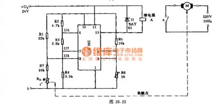
temperature control & closing protection circuit
Published:2011/5/11 2:05:00 Author:TaoXi | Keyword: temperature control, closing
Related component PDF download:
TCA965
Many machines can only be running in a certain temperature range for the best and the most economical status. If the temperature exceeds a certain permissible operating temperature, the machine may be damaged or reduce its service life. So we can use the protection circuit. This circuit uses the thermistor RH as the sensor. In order to ensure that there is no direct electrical contact between the protection circuit and the equipment, we can use the relay control.
In the condition of trouble-free or given temperature, the machine is connected by the relay. Otherwise, the relay will release and the motor will cut off.
(View)
View full Circuit Diagram | Comments | Reading(963)
Main technology parameters of Citroen ZX and DPCA-VOLCANE
Published:2011/5/19 21:40:00 Author:Borg | Keyword: Main technology parameters, Citroen ZX, DPCA-VOLCANE
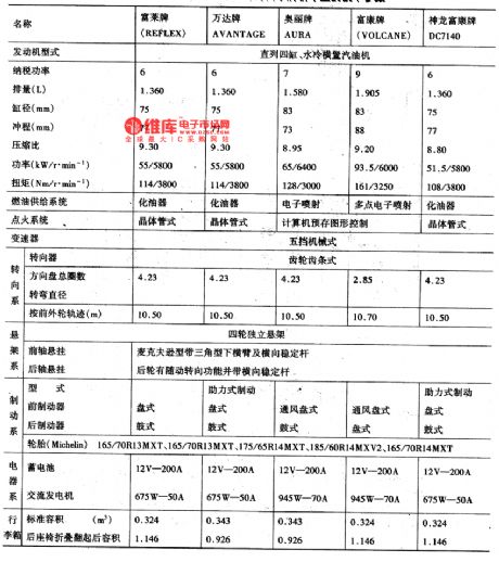

Citroen ZX, France, has many makes, the emission of RE-FLEX and AVANTAGE is 1.36L, and they are fixed with carburetor engines; both the AURA of 1.580L and VOLCANE of 1.905L use the electric control petrol injection engine. By far, the parameters of DPCA-VOLCANE DC7140 (1.6L) are close to that of RE-FLEX. The technology parameters of cars of all makes are listed in the table. Main technology parameters of Citroen ZX and DPCA-VOLCANE
(View)
View full Circuit Diagram | Comments | Reading(947)
Daewoo RACER car rear window defroster circuit diagram
Published:2011/5/16 3:24:00 Author:Nicole | Keyword: Daewoo RACERcar, rear window, defroster
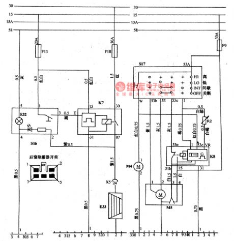
(8)rear window defroster(as shown in the figure10)
When the touch switch S16 is connected one time, it can make the timing relay K7 contact point close for 10 minutes, then the rear window defroster resistance curve is energizing and heating, at the same time, LED of S16 switch turns on, after 10 minutes, the circuit is cut off automatically. If you want to cut off it early, you can touch it again.
(View)
View full Circuit Diagram | Comments | Reading(1595)
| Pages:1766/2234 At 2017611762176317641765176617671768176917701771177217731774177517761777177817791780Under 20 |
Circuit Categories
power supply circuit
Amplifier Circuit
Basic Circuit
LED and Light Circuit
Sensor Circuit
Signal Processing
Electrical Equipment Circuit
Control Circuit
Remote Control Circuit
A/D-D/A Converter Circuit
Audio Circuit
Measuring and Test Circuit
Communication Circuit
Computer-Related Circuit
555 Circuit
Automotive Circuit
Repairing Circuit