
Circuit Diagram
Index 1768
555 simple acupuncture point detector circuit
Published:2011/5/29 19:50:00 Author:TaoXi | Keyword: 555, simple, acupuncture point, detector
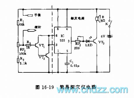
As the figure 16-19 shows, the acupuncture point detector is composed of the acupuncture point detector circuit and the trigger displaying circuit.
One detection probe of the acupuncture point detector is in the hands of the measured person, another detection probe connects to the skin of the measured person, when the probe is closing or touching the acupuncture point, the resistance between the two electrodes is low, so the composited tubes VT1 and VT2are in the saturated conductivity state, the pin-2 of 555 has low electrical level, IC sets, VT3 conducts and sends out the sound and light reminding signals, this means the point detection is right; at the position of non-acupuncture point, the skin resistance is high, VT1 and VT2 cut off, 555 is in the resetting state, there is no light siganl.
(View)
View full Circuit Diagram | Comments | Reading(4273)
Motor protector circuit diagram 17
Published:2011/5/29 2:01:00 Author:Lucas | Keyword: Motor protector
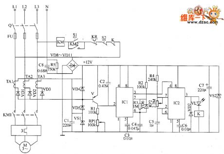
The motor protection circuit is composed of the phase pulse detection circuit, monostable trigger circuit, control circuit and power supply circuit, the circuit is shown as the chart. Phase pulse detection circuit is composed of the current transformers TA1 ~ TA3, diodes VD1 ~ VD5, Zener diode VS1 and capacitor C1. Monostable trigger circuit is composed ofthe transistor V, resistors R1 ~ R3, potentiometer RP1, capacitors C2 ~ C4, diode YD6 and time-based integrated circuit IC1. Delay control circuit is composed of the time-base integrated circuit IC2, resistor R4, capacitors C5, C6, diode VD7, light-emitting diode VL, relay K and AC contactor KM and other components. Power supply circuit consists of step-down capacitor C8, resistor R5, rectifier diodes VD8 ~ VD11, filter capacitor CT and blocking diode VS2.
(View)
View full Circuit Diagram | Comments | Reading(1120)
Motor electronic speed controller circuit diagram 2
Published:2011/5/29 2:03:00 Author:Lucas | Keyword: Motor, electronic speed controller
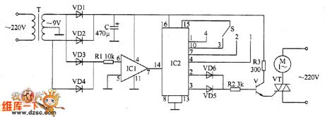
The motor electronic speed controller circuit consists of power supply circuit, the zero detection circuit and the power conditioning circuit, the circuit is shown as the chart. Power supply circuit is composed of the power transformer T, rectifier diodes VD1, VD2, and filter capacitor C. Zero detection circuit is composed of the diodes VD3, VD4, resistor R1 and Op Amp IC IC1. Power conditioning circuit consists of counting / divider integrated circuit IC2, power adjusting switch S, the diodes VD5, VD6, resistors R2, R3, transistor V and control V and thyristor VT. R1 ~ R3 use 1/4W carbon film resistors or metal film resistors. C uses aluminium electrolytic capacitor with the voltage in 25V. VD1 ~ VD6 use 1N4007 silicon rectifier diodes. V uses 59013, C8050 or 58050 silicon NPN transistor.
(View)
View full Circuit Diagram | Comments | Reading(1926)
Motor protector circuit diagram 14
Published:2011/5/29 2:01:00 Author:Lucas | Keyword: Motor protector
The motor protector circuit is composed of the power detection circuit and phase failure protection circuit, the circuit is shown as the chart. Power circuit is composed of the power transformer T, rectifier diode VD3, filter capacitor C2, current limiting resistor M and LED VL. Phase failure detection protection circuit consists of resistors R1 ~ R3, capacitor C1, diodes VD1, VD2, potentiometer RP, transistors V1, V2 and relays Κ and so on. R1 ~ R3 select 1/2W metal film resistors; Ⅲ uses the carbon film 1/4W resistor or metal film resistor. RP selects membrane potentiometer or variable resistor. C1 and C2 select aluminium electrolytic capacitor with the voltage in 16V. VD1 ~ VD3 select 1N4004 or 1N4007 diode rectifier. VL uses φ5mm ordinary light-emitting diode.
(View)
View full Circuit Diagram | Comments | Reading(905)
555 doorbell, talkback, alarm three functions circuit
Published:2011/6/2 1:01:00 Author:TaoXi | Keyword: 555, doorbell, talkback, alarm, three functions
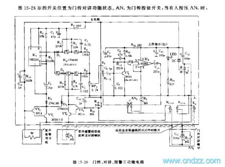
The figure 15-26 shows the switch position of the doorbell talkback functional status. AN1 is the doorbell button switch, when someone presses the AN1, the main circuit gets the power, and the two audio oscillators which is composed of the F3,F2,R4,R5,C3 and F4,F5,R7,R8,C4 start working, and it is compounded in RP1, then it adds to the VT1 to be amplified to drive the speaker. If the master opens the four-blade double-throw switch K1, the circuit is in the talkback state. If you press AN2, the voice of master will be received by the indoor speaker, then it is amplified to drive the outdoor speaker.
The main circuit which is composed of the IC1(555) and R1,R2,C1 produces the 0.5Hz low frequency oscillation.
(View)
View full Circuit Diagram | Comments | Reading(1057)
555 male and female voice electronic guest greeting circuit
Published:2011/6/2 1:02:00 Author:TaoXi | Keyword: 555, male, female, voice, electronic, guest greeting
The monostable delay circuit is composed of the IC1(555) and the R1,C1. When you areopening the door, the door control switch MK makes the pin-2 of 555 to connect with the ground, the 555 sets, the J closes, and J1-1 connects with the C4, the door control switch makes the pin-3 and pin4 of IC2 in the short-circuit state, and also the door control switch triggers the pin-3 and pin-4, so the circuit sends out the high pitch female voice thank you for coming , then the temporary stability time of the monostable circuit is up, J releases to connect the J1-1 to the C5, the circuit sends out the high pitch male voice thank you for coming . When you design the circuit parameters, the press time of the door control switch is about 3-4s, the time of broadcasting a word is about 1.4s, so we choose the monostable temporary stability time 1.4s
(View)
View full Circuit Diagram | Comments | Reading(540)
555 multi-function appliance protector circuit
Published:2011/6/2 1:02:00 Author:TaoXi | Keyword: 555, multi-function, appliance, protector
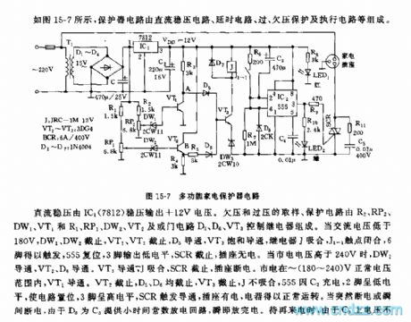
As the figure 15-7 shows, the protector circuit is composed of the DC voltage-stabilizing circuit, the delay circuit, the over-voltage under-voltage protection circuit and the execution circuit.etc.
The IC1(7812) outputs the +12V DC voltage. The over-voltage under-voltage protection circuit is composed of the R2, RP2, DW1, VT1 and R1, RP1, DW2, VT2 and the NAND gate circuit D5,D6, the relay control VT3.etc. When the AC voltage is lower than 180V, the DW1 and DW2, VT1, VT2 cut off, D5 conducts and the VT3 is saturated conduction, the realy J closes, the contact point of J1-1 closes, pin-6 triggers, 555 resets, pin-3 outputs the low electrical level, SCR cuts off, the socket has no power. When the city electricity voltage is higher than 240V, DW2, VT2, D6 conduct.
(View)
View full Circuit Diagram | Comments | Reading(981)
Motor protector circuit diagram 13
Published:2011/5/29 2:03:00 Author:Lucas | Keyword: Motor protector
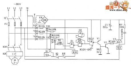
The motor protector circuit is composed of the power circuit, phase sequence detection circuit, trigger, and protection control circuit, the circuit is shown as the chart. Power circuit is composed of the power transformer T, bridge rectifier UR and filter capacitor C1. Phase sequence detection circuit is composed of the diodes VD1 ~ VD3, resistors R1 ~ R6 and Zeners VS1 ~ VS3. Trigger is composed of the D1 ~ D4 in the NAND gate IC. Protection control circuit consists of transistors V1, V2, resistors R7 ~ R9, capacitor C2, thyristor VT, and relay KA. Start button S1, stop button S2, knife switch Q, fuse FU, thermal relays KR and KM form the original control circuit of motor. R1 ~ R3 and R9 select 1W metal film resistors; M ~ R8 select 1/4W carbon film resistor or metal film resistors.
(View)
View full Circuit Diagram | Comments | Reading(2410)
Motor protector circuit diagram 6
Published:2011/6/8 3:55:00 Author:Lucas | Keyword: Motor protector
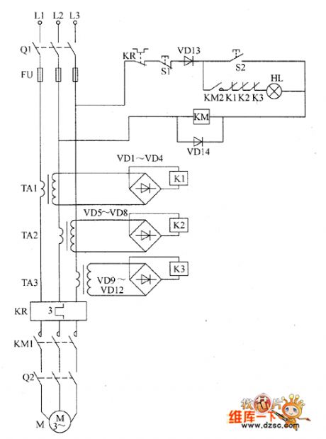
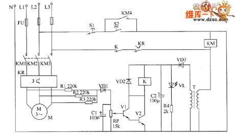
The motor protector circuit is composed of the current transformers TA1 ~ TA3, thermal relay KR, rectifier diodes VD1 ~ VD14, relays K1 ~ K3, start button S1, stop button S2 and AC contactor KM, the circuit is shown as the chart. After the the knife switch Q1 is turned on and the start button S2 is pressed, 380V AC voltage between the phase line L2 and L3 is added to the AC contactor KM by the normally closed contacts of relay KR, stop button S1, diode D13 and start button QO, and KM will operate normally, and its normally open contacts ( action contacts) KM1 and KM2 are connected, at this time if the knife switch Q2 is connected, the motor M will be energized operation. VD1 ~ VD14 use 1N4007 silicon rectifier diodes. K1 ~ K3 select JRX-13F 12V small relays. KM uses 220V or 380V AC contactor. HL uses 220V, 60W incandescent bulb.
(View)
View full Circuit Diagram | Comments | Reading(771)
Metal detector circuit diagram 1
Published:2011/6/9 3:41:00 Author:Lucas | Keyword: Metal detector
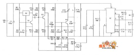
The metal detector circuit consists of the fixed frequency oscillator, mixer, detector, detection oscillator and power amplifier circuit, and the circuit is shown as the chart. Fixed frequency oscillator circuit consists of ceramic filter ZC, transistor VI and resistors R1 ~ R4, capacitor C2 and so on. Mixer consists of the mixer tube V2 and capacitor C3, resistors R5 ~ R8. Detector is composed of the diodes VD1, VD2, capacitors C8 ~ C12 and resistor R12, potentiometer RP and other components. Detection oscillator is composed of the transistor V3, inductance coil L, capacitors C4 ~ C7, C19 and resistors R9 ~ R11. Audio amplifier is composed of power amplifier integrated circuit IC, resistors R13 ~ R15, capacitors C13 ~ C18 and speaker BL.
(View)
View full Circuit Diagram | Comments | Reading(4506)
the circuit of the automatic water supplier for agriculture part 2
Published:2011/6/8 8:02:00 Author:Ariel Wang | Keyword: automatic , water supplier , agriculture
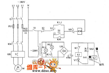
When knife-like switch and mains switch get through ,the AC 220V voltage between L1 end and N end is reduced by T.Then it generates AC 12V voltage .It is the working voltage of HL1 and HL2.At the same time ,it provides DC 12V working voltage for the detection of water level after it is commutated and filtered by UR.When the controlled water level lowers to the low water level,the permanent magnet placed on the float approaches SAI.The contacts of SAI are conducted by magneticaction of permanent magnet.VI is conducted by triggering.K1 pulls in after it is conducted.The normally open contacts K1-l and Kl-2 are connected.It lights HL2.It pulls in KM.The electric pump M works.It begins to pump.
(View)
View full Circuit Diagram | Comments | Reading(482)
the circuit of the monitor for humidity and temperature of seedling raising greenhouse
Published:2011/6/9 6:35:00 Author:Ariel Wang | Keyword: monitor, humidity, temperature, seedling raising greenhouse
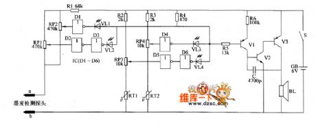
When the soil is too wet(the humidity is over the value of upper limit set by RP1),not gate D2 will output high level,not gate D3 will output low level.It lights LED .This indicates the humidity of the soil too high.At the same time,audio alarm circuit works.BL rings.When the soil is too dry(the humidity is lower than the value of low limit set by RP2),not gate D1 will output low level.It lights VL1 .This indicates the humidity of the soil too low.At the same time,audio alarm circuit works.BL rings.
(View)
View full Circuit Diagram | Comments | Reading(542)
Digital code control switch digital woven decoder MC145026/MC145027 and the mini radio transceiver module M303S/M303R
Published:2011/5/19 1:21:00 Author:TaoXi | Keyword: Digital code, control switch, digital woven decoder, mini radio transceiver
The digital code control switch digital woven decoder MC145026/MC145027 and the mini radio transceiver module M303S/M303R is as shown. When you press the transmitter button SA, the circuit gets the electricity to start working, the serial coding signal is output from the pin-15 of MC145026 and then it is sent out by the M303S launch module. Receiving module M303R of the receiving circuit receives the serial coding signal, then modulates the encoded signal and sends it to the MC145027 decoder, when the decoder's address and coding are the same, MC145027's decoding effective instruction end outputs the high-level pulse signal, the transistor VT conductsand drives the relay to close, also it completes the switch control function. (View)
View full Circuit Diagram | Comments | Reading(735)
the circuit of the electrifying intermittent controller part 1
Published:2011/6/9 6:36:00 Author:Ariel Wang | Keyword: electrifying, intermittent, controller
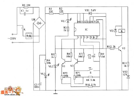
When the power-supply is turned on,the AC 220V voltage is reduced by C1.It is commutated by UR.After it is filtered by C3,it branched into 3 parts.One part is current limited by R11.It is regulated by VS1.It provides 12V working voltage for relay K.One part is current limited by R1 and R2.It is regulated by VS2,it provides +5.6V working voltage for IC.The last part light VL3 through Ⅲ.After IC is conducted to work,the 8th-pin outputs low level.It lights VL2.It stops VI and Y3.V2 is conducted.K can't be pulled in. The load is not working.VL1 is lighted.You can adjust the resistance of RP1.Or you can change the capacity of C2.You can set up the time of the load whenit ispower down(the range of adjusting is 5-120min).
(View)
View full Circuit Diagram | Comments | Reading(1209)
the control circuit of electric fence part 2
Published:2011/6/9 6:40:00 Author:Ariel Wang | Keyword: control, electric, fence
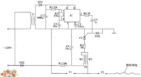
One part of the 220V AC voltage is reduced by T1.It is commutated by VD1 and it is filtered by C1.The other part is commutated by VD1.It is current limited by R1.It is filtered by C2.It provides power supply for the circuit of high voltage generator.When the impulsator gets to work,The frequency of electric impulse signal which outputs from the 3rd-pin of IC is 2Hz .It goes to the gate pole of thyristor VT by R4 and C5.So the VT is conductedy or stopped periodicity by the changing of the pulse signal.When VT is conducted,C2 discharges by the low voltage winding (winding W1) by step-up transformer.It generates pulsed high voltage on the high voltage winding of T2(winding W2).It discharges by the discharge spark interval F1 and F2. (View)
View full Circuit Diagram | Comments | Reading(2385)
the hardware interface circuit of DSP5402 and MAX3110
Published:2011/5/30 23:32:00 Author:Ariel Wang | Keyword: hardware, interface
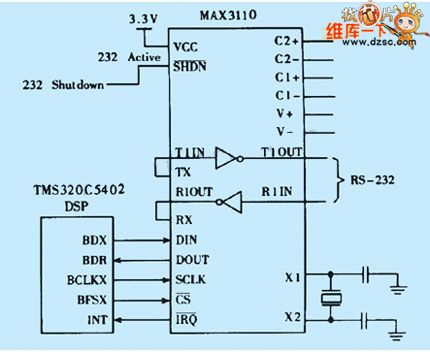
MAX3110E has full duplex communication of 16-bits data with DSP5402 through SPI port.DSP5402 sends 16-bit serial data sequence which includes transfer format CW to MAX3110,for example port setting,interruption mask,parity digit,ect.The McBSP serial interface of DSP5402 can connect directly with MAX3110 when it is SPI mode.When DSP5402's BDX1 and MAX3110's DIN is connected,it can be the sending data line.When BDR1 and DOUT is connected,itcan be the recieving data line .It sends synchronization pulse BFSX1 as the chip selecting signal.It sends clocked signal BCLKX1 as serial clock input.The hardware interface is as the chart .
(View)
View full Circuit Diagram | Comments | Reading(1250)
the watchdog and reset circuit in MSP430 SCM
Published:2011/6/1 23:36:00 Author:Ariel Wang | Keyword: watchdog, reset, SCM
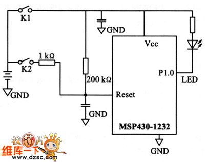
MSP430 series SCM is the new generation developed in recent years by US Texas instruments company(TI). The series is a 16-bitshybrid SCM of new concept with RISC and ultra-low power.It has ultra-low power , inner chip set outside and convenient develop method in lots of SCM series.So it becomes a shining star.It brings watchdog and reset circiut with itself.Theoretically,if the procedure has something wrong,watchdog can do the reset.But in reality,watchdog can't do everything.The experimental circuit is as the chart.
(View)
View full Circuit Diagram | Comments | Reading(1543)
The TDA1521 common accompanying sound circuit of color tv
Published:2011/5/30 23:34:00 Author:Ariel Wang | Keyword: common , accompanying sound , color tv
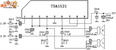
The circuit is from CHANGHONG C2191.The rejoining method is OTL dual audio track .The function of pin of TAD and voltage for reference:1st foot:11V——reverse input 1(input of L audio track signal )2nd foot:11V—— positive input 13rd foot:11V——refer to 1(when the rejoining method of OCL is 0V,when the rejoining method of OTL is 1/2Vcc)4th foot:11V——output 1(output of L audio track)5th foot:0V——input of negative power-supply (when the rejoining method is OTL earthing)6th foot:11V——output2 (output of R audio track signal)7th foot:22V——input of positive power-supply8th foot:11V——input 2 of positive direction 9th foot:11V——input 2 of reserve direction (input of R audio signal)
(View)
View full Circuit Diagram | Comments | Reading(3153)
555 anti-interference light control circuit
Published:2011/5/23 22:20:00 Author:TaoXi | Keyword: anti-interference, light control circuit
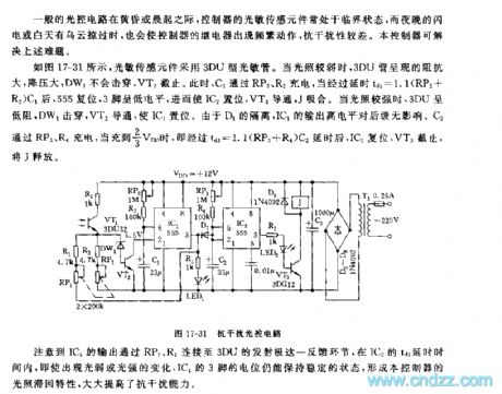
General optical circuit's photosensitive sensor is in the critical state in the evening or early morning. And the night lightning or the daytime clouds will cause the frequent movement of the relay controller, the anti-interference performance is poor. This controller can solve the above problem.
As the figure 17-31 shows, the photosensitive sensor uses the 3DU type photosensitive tube. When the illumination is weak, the 3DU tube presents the big impedance and big depressurization, DW1 will not bebroken through, VT2 cuts off. At this time, C1 is charged through RP2 and R2. After the delay time of td1=1.1(RP2+R2)C1, 555 resets, pin-3 has the low level voltage, and IC2 sets, VT3 conducts, J closes.
(View)
View full Circuit Diagram | Comments | Reading(527)
The protection circuit of 555 fridge(2)
Published:2011/5/26 23:21:00 Author:Borg | Keyword: protection circuit
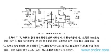
See as Figure 13-7, the circuit includes step-down rectified circuit, turning on delay circuit and controllable silicon control circuit. In the circuit, the connection of C4 and R4 can help with power failure protection. Because when it starts to electrify, the voltage on C4 can not be changed suddenly, which makes 555 reset, and the 3-pin is in a low LEV, SCR is blocked and the outlet is out of power. When C4 charges the negative pole of the capacitor, i.e the 2-pin is 1/3VDD lower than the trigger LEV, 555 is set, 3-pin is in a high LEV, SCR is conducting, and the outlet gets power. The delayed time of starting is td=1.1R4C4, and the delayed time of parameters indicated in the figure is about 6 min. (View)
View full Circuit Diagram | Comments | Reading(678)
| Pages:1768/2234 At 2017611762176317641765176617671768176917701771177217731774177517761777177817791780Under 20 |
Circuit Categories
power supply circuit
Amplifier Circuit
Basic Circuit
LED and Light Circuit
Sensor Circuit
Signal Processing
Electrical Equipment Circuit
Control Circuit
Remote Control Circuit
A/D-D/A Converter Circuit
Audio Circuit
Measuring and Test Circuit
Communication Circuit
Computer-Related Circuit
555 Circuit
Automotive Circuit
Repairing Circuit