
Circuit Diagram
Index 1772
The 875p computer main board circuit (094)
Published:2011/6/10 1:33:00 Author:Seven | Keyword: main board
View full Circuit Diagram | Comments | Reading(644)
The over-current protection circuit of thyristors
Published:2011/6/9 0:11:00 Author:Seven | Keyword: over-current protection circuit, thyristor
View full Circuit Diagram | Comments | Reading(738)
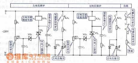
The transistor over/low-voltage protection circuit
Published:2011/6/9 0:12:00 Author:Seven | Keyword: over/low-voltage, protection circuit
View full Circuit Diagram | Comments | Reading(810)
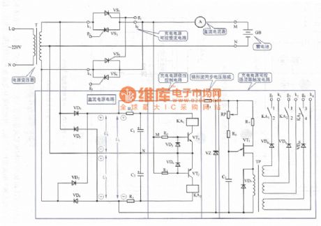
The nonpolarity charging circuit
Published:2011/6/9 0:13:00 Author:Seven | Keyword: charging circuit
View full Circuit Diagram | Comments | Reading(698)
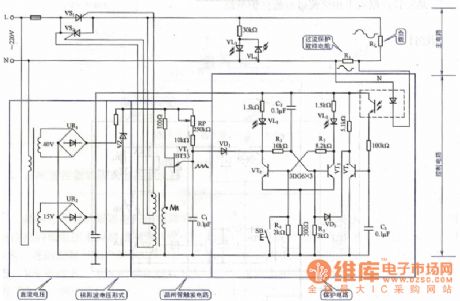
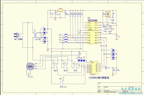
The switch power supply circuit of single chip microcomputers and developing devices
Published:2011/6/10 1:34:00 Author:Seven | Keyword: power supply circuit, single chip microcomputers
This text is to introduce a switch power supply which is used in the developing devices of single chip microcomputers or lab electric devices. This circuit characterizes stable output, adjustable voltage, small size, steady functions and so on. The output switch power supply output is 1.8A, the output voltage ranges +15v~+5v which can be set, and the input voltage is fit for the power supply of AC90v~240v 50/60HZ, so it can provides with power for lab electric experiment measuring devices, and it can also be used to charge the battery of 6v/12v.
(View)
View full Circuit Diagram | Comments | Reading(726)
The FAW Toyota-Reiz engine control diagram (2)
Published:2011/6/9 0:16:00 Author:Seven | Keyword: Toyota-Reiz, engine control
View full Circuit Diagram | Comments | Reading(872)
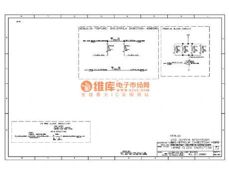
The Faw Toyota-Reiz ignition system circuit
Published:2011/6/9 0:22:00 Author:Seven | Keyword: Toyota-Reiz, ignition system
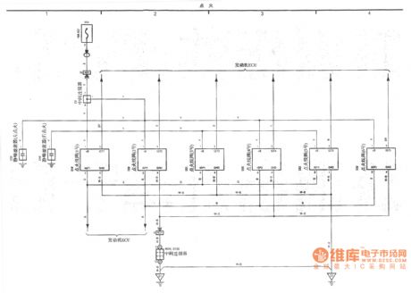
See as the figure. The Faw Toyota-Reiz ignition system circuit (View)
View full Circuit Diagram | Comments | Reading(518)
The on-line tester circuit of diodes and triodes
Published:2011/6/10 1:36:00 Author:Seven | Keyword: on-line tester, diodes and triodes
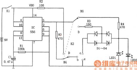
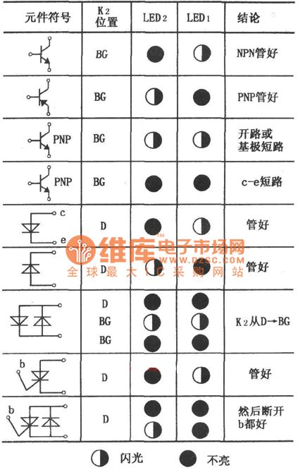
In the circuit is the on-line tester circuit of diodes and triodes. The tester consists of the multi-resonate oscillator and single steady trigger centralized on the dual time-based 556 circuit, LED1 and LED2, etc.The multi-resonate oscillator consists of half of 556, R1 and C1, etc, whose oscillating frequency is f=1.44/R1C1. The single steady trigger consists of the other half of 556, by which the output poles of 5-pin and 9-pin output a couple alternating square wave testing signals, and the couple of signals have opposite polarities and the peak voltage is 9v, the frequency is 5Hz.
(View)
View full Circuit Diagram | Comments | Reading(704)
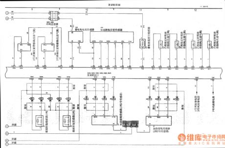
The FAW Toyota-Reiz engine control diagram (1)
Published:2011/6/10 1:35:00 Author:Seven | Keyword: Toyota-Reiz, engine control
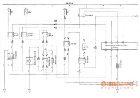
See as the figure, this is the FAW Toyota-RuiZhi engine control diagram (1) (View)
View full Circuit Diagram | Comments | Reading(602)
The Faw Toyota-Reiz cooling fan diagram
Published:2011/6/9 0:18:00 Author:Seven | Keyword: Toyota-Reiz, cooling fan
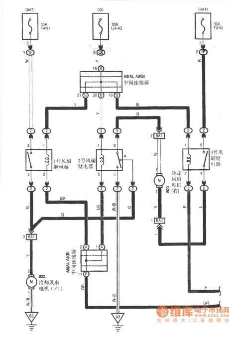
See as the figure. The Faw Toyota-Reiz cooling fan diagram (View)
View full Circuit Diagram | Comments | Reading(586)
precision bridge isolation and measurement amplifier circuit
Published:2011/5/15 1:04:00 Author:John | Keyword: isolation and measurement amplifier circuit, precision bridge
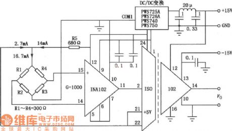
Bridge isolation and measurement amplifier circuit is widely used for industrial process control, which is composed of ISO102 and INA102 with low noise and low power comsuption. Just as shown in the figure. ISO102 is capacitor coupled buffer and isolation amplifier circuit, having a gain of 1000. It is mainly used for 300Ω bridge signal amplification. The power supply of a bridge is completed by the two parts. One is that the supply side(INA102 12 feet) provides l4mA current through the 680Ω resistor, the other is that the +5 V reference from the ISO102 incentive provides 2.7mA current. The plused 16.7mA current powers the bridge. Changing signal of the bridge can be directly input to the differential input point of INA102. It can achieve isolation amplifier of both bridge signal and output voltage Uo. The measurement circuit is powered by PWS725A or PWS726A and other DC / DC conversion devices. So the implementation of no common ground and no total power supply can be achieved in isolated parts. The circuit can be directly used for accurate measurement of direct pressure, weight and physical strain and so on. (View)
View full Circuit Diagram | Comments | Reading(1101)
universal dual power quad op-amp circuit
Published:2011/5/15 1:06:00 Author:John | Keyword: dual power, quad op-amp

(View)
View full Circuit Diagram | Comments | Reading(1071)
integrated circuit typical application circuit
Published:2011/5/15 1:01:00 Author:John | Keyword: Typical application circuit, integrated circuit
 (View)
View full Circuit Diagram | Comments | Reading(668)
dual power three op-amp with high input impedance circuit
Published:2011/5/15 0:57:00 Author:John | Keyword: dual power, three op-amp, high input impedance

View full Circuit Diagram | Comments | Reading(967)
LDQ852-1Integrated inside circuit box circuit
Published:2011/5/27 7:10:00 Author:John | Keyword: Integrated circuit, inside circuit box

LDQ852-1 integrated circuit mainly consists of an audio oscillator Fl and a frequency divider with grade four trigger. Power regulator II can regulate the power voltage between 3.5V-4.2V, which is able to actuate vibrato generator F2. Vibrato generator F2 is a low frequency oscillator, whose external components determine the frequency of the vibrato. Power regulator I can regulate the power voltage between 3.8V-4.5V, which is used to drive the scale generator and requency divider to work. The inside circuit box circuit has been shown.
(View)
View full Circuit Diagram | Comments | Reading(507)
The electric adjuster circuit of touch fans
Published:2011/6/10 0:54:00 Author:qqtang | Keyword: electric adjuster, touch fans
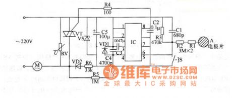
The working principle of the circuitThe adjuster circuit consists of the integrated circuit IC, two-way thyristor VT and external elements, see as figure 1.
When it is in the mains of 200v, the speed regulator is starting to work, but the two-way thyristor is blocked and the fan motor M is still. When the hand touches the electrode plate and the touching time is not less than 0.4s, the 8-pin if IC outputs a solid high LEV, then the thyristor is conducting and M begins to run. However, the speed regulator just works as a switch. (View)
View full Circuit Diagram | Comments | Reading(602)
The integrated amplifier circuit of TDA6107JF single chip video
Published:2011/6/4 2:27:00 Author:qqtang | Keyword: amplifier circuit, single chip
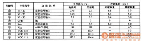
TDA6107JF is an integrated amplifier circuit of TDA6107JF single chip video, which is widely used in all kinds of local and imported big screen color TV as the terminal amplifier. 1.function features TDA6107JF contains a video amplifier circuit(i.e R,G and B, 3 ways of primary colour amplifier), black current generating circuit and other additional function circuits, etc.
2.pin functions and dataTDA6107JF is in a 9-pin single line package, whose pin functions and data are listed in Table 1.Table 1. Pin functions and data of TDA6107JF
(View)
View full Circuit Diagram | Comments | Reading(1937)
SSM2250 multi-function low-power amplifier integrated circuit
Published:2011/6/10 0:54:00 Author:qqtang | Keyword: multi-function, low-power amplifier
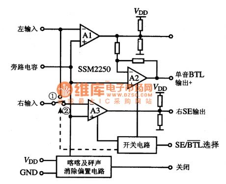
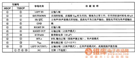
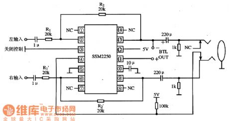
1.function featuresSSM2250 includes 3 full amplitude(output amplitude value is close to that of power supply) computing amplifiers, kluck and Ping sound removing bias circuit and switch control circuit, etc. Its internal circuit is shown in the figure.
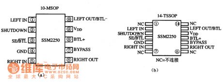
The internal circuit of SSM22502.pin functionsSSM2250 has two kinds of packages: 10-pin MSOP and TSSOP, whose pin sequence is shown in the figure, and the two packages with their relationship and the pin functions are listed in the table.
(View)
View full Circuit Diagram | Comments | Reading(787)
SM5875BM—the D/A shift integrated circuit
Published:2011/6/10 0:56:00 Author:qqtang | Keyword: D/A shift, integrated circuit
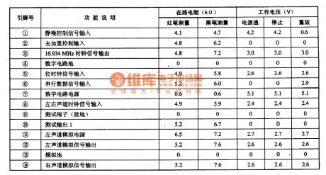
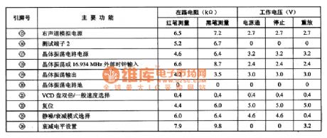
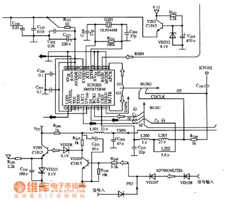
1.function featuresSM5875BM includes 8-time over sampling digital filter and stimulating signal low-pass filter, which consists of serial data input connector, digital filter diminish control circuit, 3 stage noise rectifier circuit, attenuation counter, sequence controller, PWM data generator, clock generating circuit and analog signal low-pass filter, etc. Its functions include digital signal deemphasis, digit or volume attenuation, silence/mute, standard/multiple mode selecting and low-voltage power supply. Its internal circuit is shown in the figure.
(View)
View full Circuit Diagram | Comments | Reading(1590)
The outline circuits of some digital boards
Published:2011/6/10 0:56:00 Author:qqtang | Keyword: outline circuit, digital board
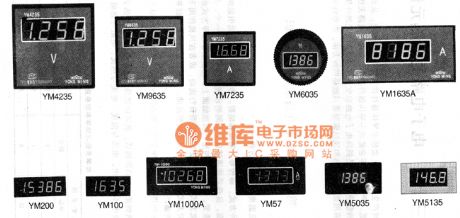
The digital board consists of special integrated circuits, highly stable reference power supply and digital display components. The digital board characterizes high precision, strong antijamming capability, good reliability, wide working temperature and convenient installation, which is a replacement of the pointer type. The digital board can be directly used in all kinds of electricity parameter tests, such as working with sensors, and it can also be used in non-electricity parameter tests, such as military strength, temperature and movement,etc.
Figure: The outlines of some digital boards (View)
View full Circuit Diagram | Comments | Reading(486)
| Pages:1772/2234 At 2017611762176317641765176617671768176917701771177217731774177517761777177817791780Under 20 |
Circuit Categories
power supply circuit
Amplifier Circuit
Basic Circuit
LED and Light Circuit
Sensor Circuit
Signal Processing
Electrical Equipment Circuit
Control Circuit
Remote Control Circuit
A/D-D/A Converter Circuit
Audio Circuit
Measuring and Test Circuit
Communication Circuit
Computer-Related Circuit
555 Circuit
Automotive Circuit
Repairing Circuit