
Circuit Diagram
Index 468
LM2002, LM2002A 8W Audio power amplifier circuit diagram
Published:2011/8/31 2:41:00 Author:Rebekka | Keyword: 8W , Audio power amplifier
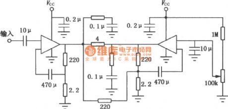
LM2002/2002Ais theaudio power amplifier IC. It uses 5-pin single in-line plastic package. The features of the two ICs are large output power, less distortion, low noise, small number of external components, high input impedance, low noise of power shock etc. LM2002 has limiting current and thermal shutdown protection circuit; LM2002A has a high voltage protection. The maximum instantaneous power supply voltage is up to 40V. They are suitable for the audio power amplifier of car audio systems, ordinary portable or desktop recorder. The BTU circuit is shown as the chart. (View)
View full Circuit Diagram | Comments | Reading(1518)
The integrated circuit diagram of two-channel audio power amplifier
Published:2011/9/18 21:16:00 Author:Ecco | Keyword: Two-channel audio , power amplifier , integrated circuit
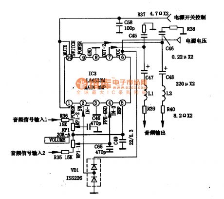
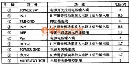

LA4533M is the two-channel audio power amplifier integrated circuit produced by Sanyo of Japan, and it is widely used in pocket radio, Walkman and other low-voltage, low-power audio system. 1. LA4533M internal block diagram and pin functions LA4533M manifold is mainly composed of two-way power amplifier circuit, power-off mute switch circuit, ripple filter circuit. The manifold internal block diagram is shown in Figure 1, the IC uses 10-pin dual flat plastic structure, and the integrated circuit pin functions and data are listed in Table 1.
(View)
View full Circuit Diagram | Comments | Reading(1502)
Plastic recycling machine control circuit diagram
Published:2011/9/16 1:51:00 Author:Ecco | Keyword: Plastic recycling machine, control circuit
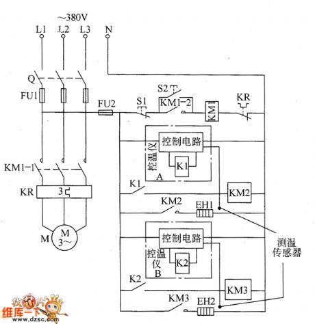
The plastic recycling machine control circuit is composed of the main control circuit of the motor and heater temperature control circuit, and it is shown as the chart. The main control circuit of the motor is composed of the knife switch Q, fuses FU1 and FU2, AC contactor KM1, thermal relay KR, stop buttons S1, S2 and motor start button M. Heater temperature control circuit is composed of the AC contactors KM1 and KM2, temperature control device A, temperature control device B, plastic preheating ring heater EH1 and melting electric heater EH2. KM2 and KM3 use the AC contactors with coil voltage in 220V.
(View)
View full Circuit Diagram | Comments | Reading(1597)
The temperature controller circuit diagarm 2
Published:2011/9/18 21:15:00 Author:Ecco | Keyword: Temperature controller
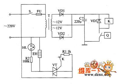
The temperature controller is composed of the power supply circuit and temperature detection control circuit, and it is shown as the chart. Power supply circuit is composed of the power switch s, fuse FU, power transformer T, rectifier diodes VDI, VD2 and filter capacitor C. Temperature measurement control circuit is composed of electric hot thermometer Q, relay Κ, diode VD3, resistors RI, R2, thyristor VT, neon light HL and electric heater EH. RI and R2 use the 1/4W carbon film resistors or metal film resistors.
(View)
View full Circuit Diagram | Comments | Reading(794)
SS0604 Touching stepping dimmer circuit diagram
Published:2011/8/9 20:16:00 Author:Ecco | Keyword: Touching stepping dimmer
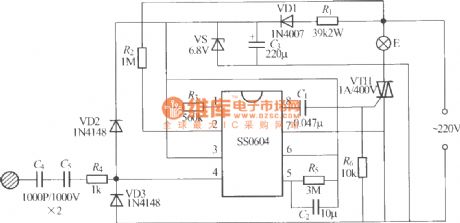
The five-speed four-step touching stepping dimmer shown as the chart is composed of the SS0604 integrated circuit, and touching the M repeatedly, the lamp brightness of E will changein the cycle of low, medium, medium to high, the brightest, turning off ... for the user to select.
(View)
View full Circuit Diagram | Comments | Reading(1241)
Cycle timing controller 5
Published:2011/8/9 20:15:00 Author:Ecco | Keyword: Cycle timing controller
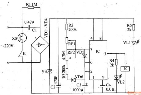
The cycle timing control circuit is composed of the power supply circuit and timing control circuit, and it is shown in Figure 3-93. The power supply circuit is composed of the step-down capacitor Cl, resistors Rl, R5, rectifier diodes VDl-VD4, voltage regulator diode VS, power indicator LED VLl and filter capacitor C2. Timing control circuit consists of the time-base IC, resistors R2-R4, capacitor C3, potentiometers RPl, RP2, diodes VD5, VD6, light-emitting diode VL2 and relay K. Rl selects the 1/2W carbon film resistor; R2-R5 use 1/4W carbon film resistors or metal film resistors. RP1 and RP2 select the small linear synthetic membrane potentiometers.
(View)
View full Circuit Diagram | Comments | Reading(1251)
Electric oven temperature controller
Published:2011/8/9 20:14:00 Author:Ecco | Keyword: Electric oven , temperature controller

The electric oven temperature controller circuit is composed of the power supply circuit and temperature detection control circuit, and it is shown in Figure 3-80. Power supply circuit is composed of the power switch S, fuse FU, power transformer T, rectifier diodes VDl, VD2 and filter capacitor C. The temperature detection control circuit is composed of electric hot thermometer Q, relay K, diode VD3, resistors Rl, R2, Crystal thyristor VT, neon light HL and electric heater EH. Rl and R2 use the 1/4W carbon film resistors or metal film resistors. C selects the aluminum electrolytic capacitor with voltage in 25V. VDl-VD3 use the 1N4007 silicon rectifier diodes.
(View)
View full Circuit Diagram | Comments | Reading(4466)
Automatic feed controller
Published:2011/8/9 20:14:00 Author:Ecco | Keyword: Automatic feed controller
The automatic feed controller circuit is composed of the power supply circuit, pulse oscillator, electromagnetic control circuit and motor control circuit, and it is shown in Figure 4-42. Power supply circuit is composed of the knife switch Q, fuses FUl-FU3, buck capacitors Cl, C2, discharge resistor Rl, control switch S, relay K, rectifier diode VDl, voltage regulator diode and filter capacitor C3. Pulse oscillator is composed of the resistor R6, potentiometers RPl, RP2, diodes VD3, VD4, capacitor Cl2 and time-base IC. Solenoid control circuit consists of the electromagnet YA, resistors R7-R9, RI3, potentiometer RP3, diodes VD2, VD5, transistor V, capacitor C5 and thyristor VTl.
(View)
View full Circuit Diagram | Comments | Reading(790)
Wiring diagram of DC meter
Published:2011/9/18 20:47:00 Author:Ecco | Keyword: wiring diagram , DC meter
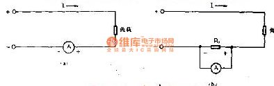
Ammeter is used to measure the current in the circuit for the electricians, and meter is connected to tested circuit in series. The positive pole of DC ammeter should be connected to the positive terminal of DC power supply. The limiting amount of the instrument shoulf be 1.5 to 2 times of measuring current. Figure A shows the direct access method of DC ammeter, and b is the access method of the DC ammeter with external shunt.
(View)
View full Circuit Diagram | Comments | Reading(782)
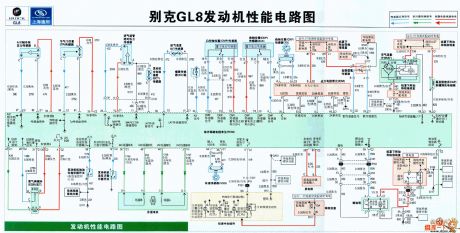
The motor performance circuit diagram of BUICK GL8
Published:2011/9/18 21:09:00 Author:Ecco | Keyword: Motor performance
View full Circuit Diagram | Comments | Reading(803)
Numeric control instrument of photoconductive control circuit diagram
Published:2011/8/2 1:09:00 Author:Ecco | Keyword: Numeric control instrument, photoconductive control
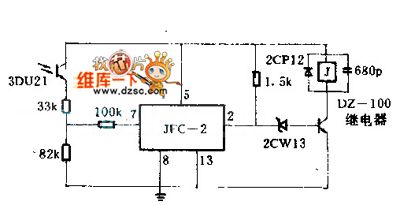
when a arbitrarily warping wire breaks, the light shield held by this warping wire will fall down, simultaneously, the light shield turns back the light that from the 3DU21 photosensitive tube, and the relay in the warping wire will be released, and that will make a parking by controlling its motor.
(View)
View full Circuit Diagram | Comments | Reading(840)
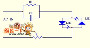
The LED driver circuit diagram
Published:2011/9/18 21:08:00 Author:Ecco | Keyword: LED driver
View full Circuit Diagram | Comments | Reading(1206)
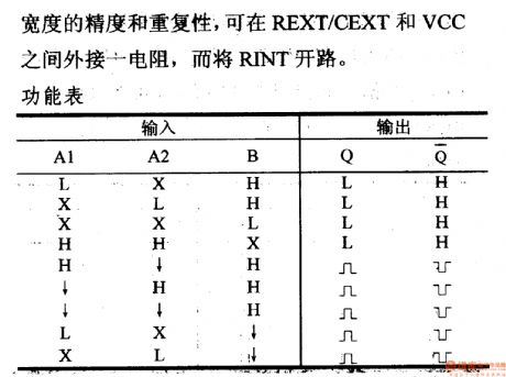
The 74 series digital circuit of 74123 74L123 double monostable multivibrator
Published:2011/9/18 21:07:00 Author:Ecco | Keyword: The 74 series, digital circuit, double monostable multivibrator
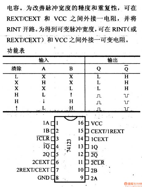
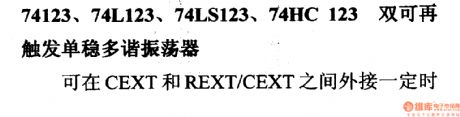
Capacitance. To improve the precision and repeatability of the pulse width, it could connect a resistance between REXT/CEXT and VCC, and open for RINT. In order to get the variable pulse width, it could connect a variable resistance between RINT and VCC.
74123, 74L123, 74LS123, 74HC123 double monostable multivibrator (View)
View full Circuit Diagram | Comments | Reading(2740)
The 74 series digital circuit of 74121 74L121 monostable multivibrator
Published:2011/9/18 21:06:00 Author:Ecco | Keyword: 74 series, digital circuit, monostable multivibrator
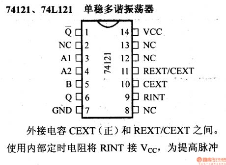
To improve the precision and repeatability of the pulse width, it could connect a resistance between REXT/CEXT and VCC, and open for RINT.
To improve pulse width, it could connect atiming resistance betweenREXT/CEXT and CEXT. (View)
View full Circuit Diagram | Comments | Reading(2368)
The power failure alarm circuit
Published:2011/9/18 20:56:00 Author:Ecco | Keyword: Power failure , alarm circuit
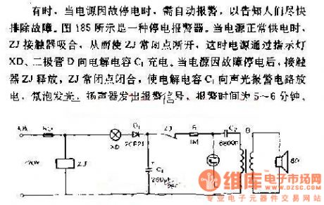
Sometimes, when the power is black out for some reasons, it needs to alarm automatically to inform people overcoming the breakdown as soon as possible. Figure 185 shows a power failure alarm. When power supply works normally, ZJ contactors pull in, so that the ZJ normal closed contact cuts off, then power is charged by the electrolytic capacitor C1 between the lights XD and diode D. When the power is black out for some reasons, ZJ contactors release, so that electrolytic capacitor C1 discharges to the sound and light alarm circuit, neon light bulbs turn on, speakers emit alarm signals, the alarm time is 5 to 6 minutes.
(View)
View full Circuit Diagram | Comments | Reading(992)
Two Wien Bridge low-frequency signal generators for self-made
Published:2011/8/2 1:11:00 Author:Ecco | Keyword: Wien Bridge, low-frequency , signal generator , self-made
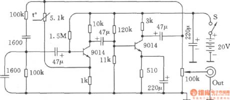
Low frequency signal generator is the common equipment for electronic production debugging, maintenance, here are two circuits, the performance are very good. The two 100kΩ resistors in figure and two 1600pF capacitors determine the oscillation frequency of RC series-parallel selective circuit, it is calculated as f = 1 ÷ (6.28 × R × C). If the unit of R uses kΩ, the unit of C uses μF, the unit of f is kHz, so changing the value of R and C according to the calculation, then you can get a different oscillation frequency. The frequency of RC circuit diagram is l000Hz. It should be noted, the value of resistors and capacitors in two series-parallel network must be the same. This circuit has the advantage of easy startup, good wave and reliable work, it is often called the Wien Bridge oscillator circuit.
(View)
View full Circuit Diagram | Comments | Reading(950)
The Colpitts oscillator
Published:2011/9/18 20:55:00 Author:Ecco | Keyword: colpitts , oscillator
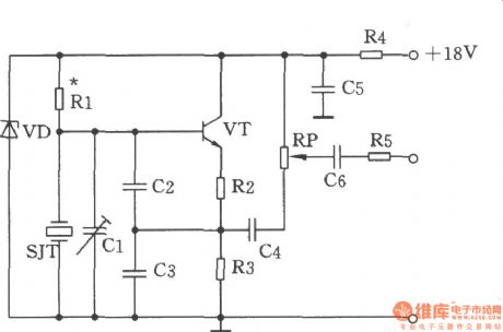
Figure shows the Colpitts oscillator circuit. It has a base frequency crystal, and the frequency is 1499 kHz, crystal SJT is connected to the both ends of capacitor C2, C3. Emitter divider resistor R2, R3 provide basic feedback signal, the feedback voltage is controlled by the capacitive dividers C2, C3. SJT crystal provides l499kHz sine wave signal for the base of the transistor VT after working. And it is output by VT emitter output VT.
Resistors R1 provides a 18V step-down voltage for a proper bias voltage of VT, appropriately adjusting resistor R1 could make Colpitts oscillator work in the soft excitation state. Resistor R4, capacitor C5 is post-coupling circuit. Regulating capacitor C1 can fine-tune the oscillator working frequency. Adjusting potentiometer RP can change the oscillation signal output level. Selecting components: capacitors Cl, 5 ~ 20p, C2 to 51p, C3, C6 to 100p, C4 to 15p, C5 is 100μ/32V. Resistor Rl is 62kΩ, R2 is 300Ω, R3 is 2.4kΩ, R4 is 360Ω, 1/2W, R5 is 15kΩ. Potentiometer RP is 4.7kΩ. Transistor VT is 3DGl20C, 65 ≤ β ≤ 115. Zener diode VD uses 2CW58. crystal SJT uses JA5B-1499Hz.
(View)
View full Circuit Diagram | Comments | Reading(3011)
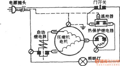
Arctic ocean - Ariston BYD-177 refrigerator
Published:2011/9/18 20:49:00 Author:Ecco | Keyword: arctic ocean , Ariston , refrigerator
View full Circuit Diagram | Comments | Reading(1299)
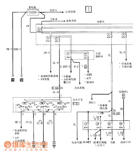
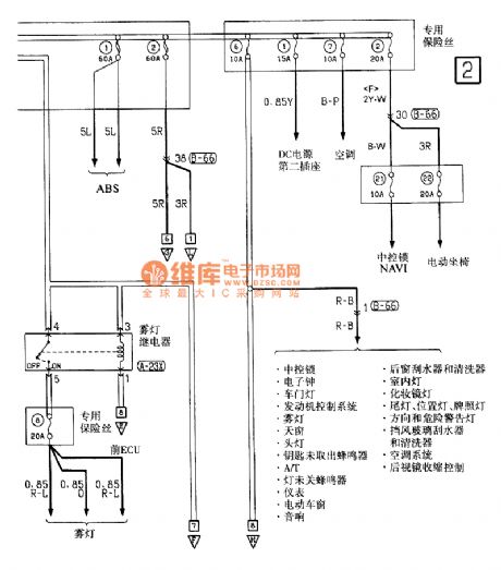
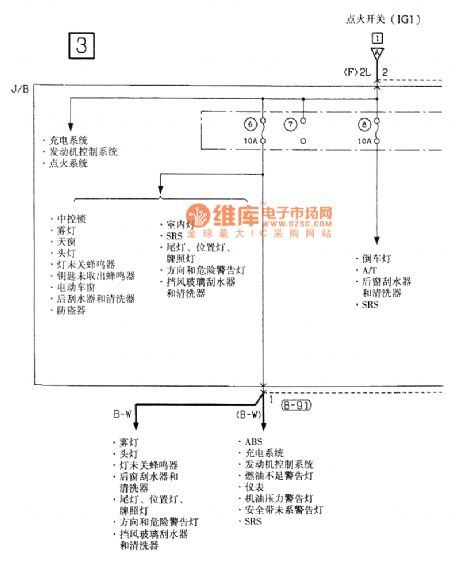
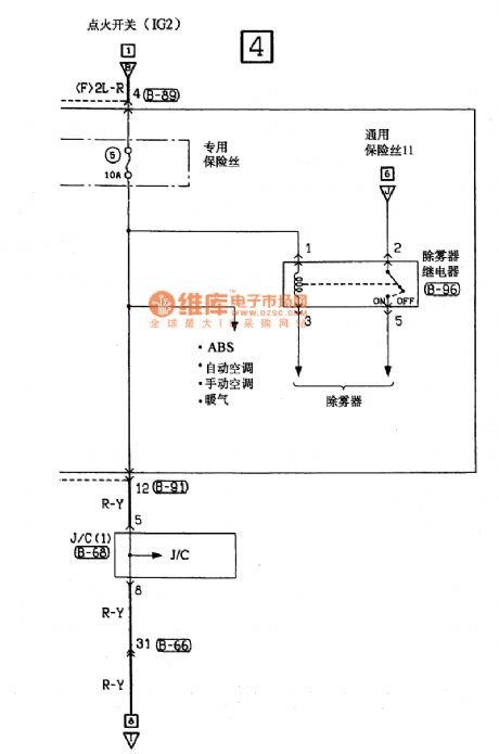
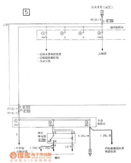
Southeast Soveran power supply electrical system circuit diagram
Published:2011/9/18 20:54:00 Author:Ecco | Keyword: Southeast Soveran , power supply , electrical system
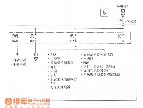
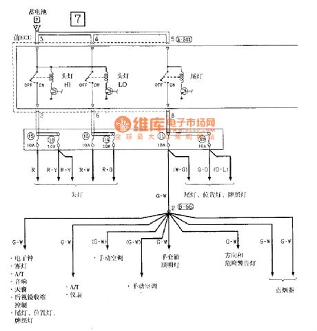
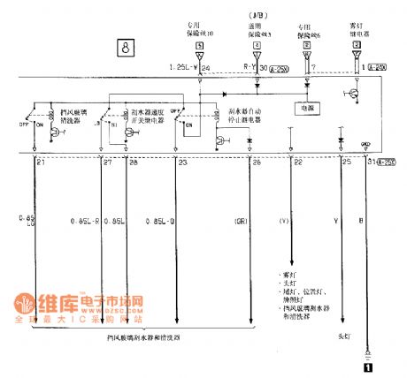
View full Circuit Diagram | Comments | Reading(764)
The converter circuit diagram with MAX668
Published:2011/8/2 1:12:00 Author:Ecco | Keyword: converter, MOSFET
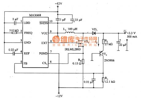
Figure shows the converter circuitwith MAX668, and MAX668 is a core component of the circuit, and it is a switching power supply integrated controller with PWM operation. The circuit shown in Figure 5 is a boost circuit which can switch -12V voltage into +3.3 V or +5 V. The RS in the circuit is sensitive resistor, which can limit the peak current to 12OmA, and N-channel switch MOSFET VT1 uses the low-cost devices with logic level.
(View)
View full Circuit Diagram | Comments | Reading(1393)
| Pages:468/2234 At 20461462463464465466467468469470471472473474475476477478479480Under 20 |
Circuit Categories
power supply circuit
Amplifier Circuit
Basic Circuit
LED and Light Circuit
Sensor Circuit
Signal Processing
Electrical Equipment Circuit
Control Circuit
Remote Control Circuit
A/D-D/A Converter Circuit
Audio Circuit
Measuring and Test Circuit
Communication Circuit
Computer-Related Circuit
555 Circuit
Automotive Circuit
Repairing Circuit