
Measuring and Test Circuit
Index 72
SIGHT_N’SOUND_METRONOME
Published:2009/6/25 21:03:00 Author:May
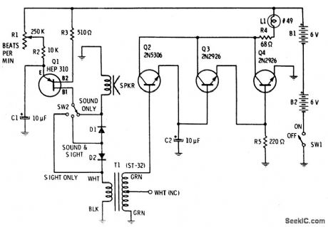
Precise, adjustable control of beats per minute from a largo of 18 to a frenzied, high presto of 500. These beiats are produced acoustically through a speaker. A light flashes at the same rate. When SW1 is closed, C1 begins to charge through R1 and R2. C1 will eventually reach a voltage at which the emitter of unijunction transistor is switched on, dumping the energy stored in C1 into an 8 ohm speaker. To produce a distinct plop , brief pulses across T2 secondary drive Q2 into conduction. The extra gain of Q3 and Q4 are sufficient to briefly switch L1 on, then off, as the pulse wave passes. Capacitor C2 stretches the pulse slightly to overcome the thermal inertia of the lamp, so that a bright flash occurs. (View)
View full Circuit Diagram | Comments | Reading(0)
ACCENTUATED_BEAT_METRONOME
Published:2009/6/25 21:01:00 Author:May
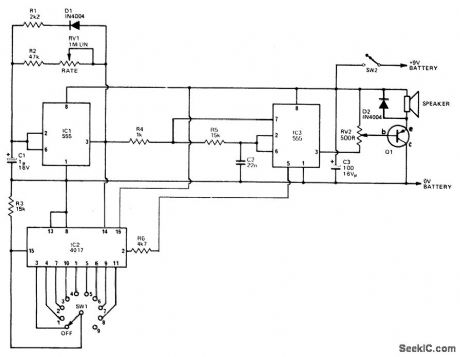
IC3 acts as an oscillator which operates if the output of IC1 is high. With the values used the two frequencies produced are about 800 Hz and 2500 Hz. The output is buffered by Q1 which drives the speaker. The first IC is used to generate the tone duration and the time interval between beats. The interval is adjustable by RV1 while the tone duration is set by R1. The output of IC1 also clocks IC2, adecade counter with 10 decoded outputs. Each of these outputs go high in sequence on each clock. The second output of IC2 is connected to the control input of IC3 and is used to change the frequency. Therefore the first tone will be high frequency, the second low and the third to tenth will be high again. This gives the 9-1 beat. If for example the 5th output is connected to the reset, the first tone will be high, the second low, and the third and fourth high, then when the 5th output goes to a high it resets it back to the first which is a high tone. We then have 3 high and one low tones or a 3-1. (View)
View full Circuit Diagram | Comments | Reading(753)
LO_PARTS_TREASURE_LOCATOR
Published:2009/6/25 20:59:00 Author:May
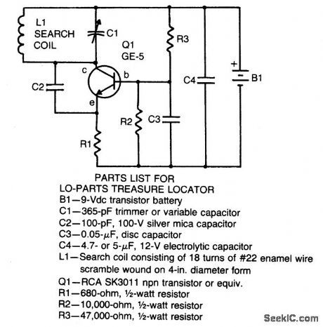
Locator uses a transistor radio as the detector. With the radio tuned to a weak station, adjust C1 so the locator oscillator beats against the received signal. When the search head pas-ses over metal, the inductance of L1 changes thereby changing the locator oscillator's frequency and changing the beat tone in the radio.The search coil consists of 18 turns of #22 enameled wire scramble wound on a 4-in.diameter form. After the coil is wound and checked for proper operation, saturate the coil with RTV adhesive for stable operation of the locator. (View)
View full Circuit Diagram | Comments | Reading(1109)
MICROPOWER_METAL_DETECTOR
Published:2009/6/25 20:57:00 Author:May
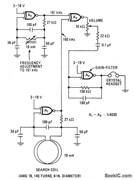
This battery-powered metal detector uses four exclusive-OR gates contained in the 4030 CMOS integrated circuit. The gates are wired as a twin-oscillators and a search coil serves as the inductance element in one of the oscillators. When the coil is brought near metal, the resultant change in its effective inductance changes the oscillator's frequency.Gates A1 and A2 form the two oscillators which are tuned to 160 and 161 kilohertz respectively. The pulses produced by each oscillator are mixed in A3, its output contains sum and difference frequencies at 1 and 321 kHz. The 321 kHz signal is filtered out by the 10 kHz low-pass filter at A4, leaving the 1 kHz signal to be amplified for the crystal headset connected at the output. The device's sensitivity is sufficient to detect coinsized objects a foot away. (View)
View full Circuit Diagram | Comments | Reading(5920)
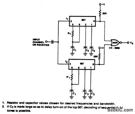
DUAL_TONE_DECODER
Published:2009/6/25 20:57:00 Author:May
View full Circuit Diagram | Comments | Reading(1)
ZENER_DIODE_CHECKER
Published:2009/6/25 20:56:00 Author:May
View full Circuit Diagram | Comments | Reading(814)
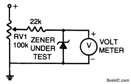
PRECISION_CALIBRATION_STANDARD
Published:2009/6/25 20:56:00 Author:May
An external power supply that gives a voltage higher than the highest expected rating of the zener diodes to be tested is required.Potentiometer RV1 is adjusted until the meter reading stabilizes. This reading is the zener diode's breakdown voltage. (View)
View full Circuit Diagram | Comments | Reading(702)
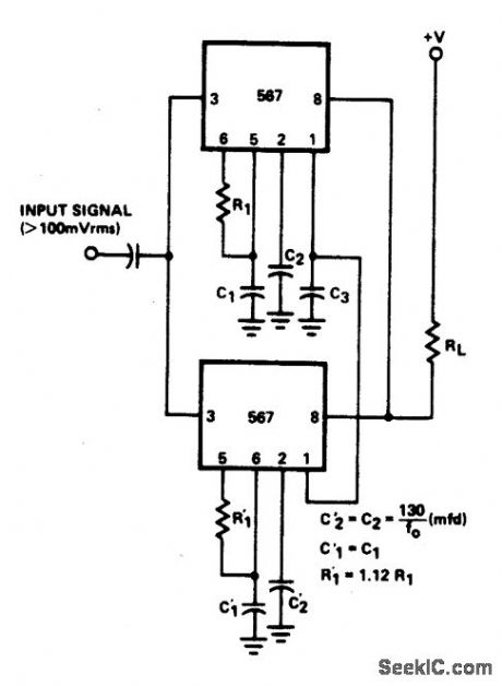
24%BANDWIDTH_TONE_DECODER
Published:2009/6/25 20:55:00 Author:May
View full Circuit Diagram | Comments | Reading(639)
PHASE_METER
Published:2009/6/25 20:55:00 Author:May

View full Circuit Diagram | Comments | Reading(0)
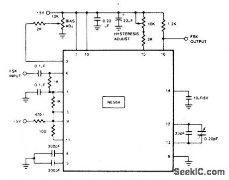
108_MHz_FSK_DECODER
Published:2009/6/25 20:54:00 Author:May
View full Circuit Diagram | Comments | Reading(0)
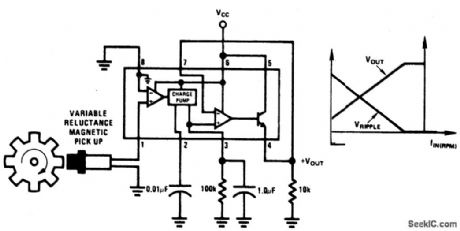
MINIMUM_COMPONENT_TACHOMETER
Published:2009/6/25 20:54:00 Author:May
View full Circuit Diagram | Comments | Reading(0)
SENSITIVE_RE_VOLTMETER
Published:2009/6/25 20:53:00 Author:May
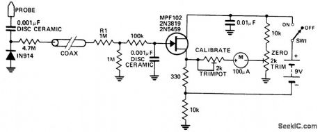
This circuit measures RF voltages beyond 200 MHz and up to about 5 V. The diode should be mounted in a remote probe, close to the probe tip. Sensitivity is excellent and voltages less than 1 V peak can be easily measured. The unit can be calibrated by connecting the input to a known level of RF voltage, such as a calibrated signal generator, and setting the calibrate control. (View)
View full Circuit Diagram | Comments | Reading(0)
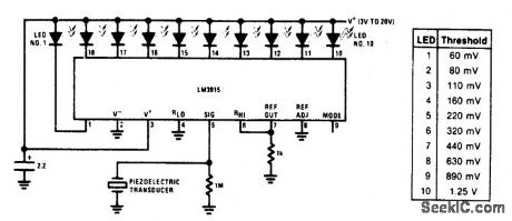
VIBRATION_METER
Published:2009/6/25 20:52:00 Author:May
View full Circuit Diagram | Comments | Reading(0)
SCA_BACKGROUND_MUSIC_DECODER
Published:2009/6/25 20:52:00 Author:May
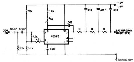
A resistive voltage divider is used to es-tablish a bias voltage for the input (pins 2 and 3). The demodulated (multiplex) FM signal is fed to the input through a two-stage high-pass filter, both to effect capacitive coupling and to attenuate the strong signal o f the regular chan-nel. A total signal amplitude, between 80 mV and 300 mV, is required at the input. Its source should have an impedance of less than 10,000 ohms. The Phase Locked Loop is tuned to 67 kHz with a 5000 ohm potentiometer; only ap-proximate tuning is required, since the loop will seek the signal. The demodulated output (pin 7) passes through a three-stage low-pass filter to provide de-emphasis and attenuate the high-frequency noise which often accompanies SCA transmission. The demodulated output signal is in the rder of 50m V and the frequency response extends to 7 kHz. (View)
View full Circuit Diagram | Comments | Reading(0)
SOUND_LEVEL_MONITOR
Published:2009/6/25 20:50:00 Author:May
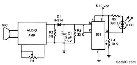
Loudness detector consists of a 555 IC wired as a Schmitt trigger. The output changes state—from high to low—whenever the input crosses a certain voltage. That threshold voltage is established by the setting of R4. (View)
View full Circuit Diagram | Comments | Reading(1410)
DIODE_TESTER
Published:2009/6/25 20:48:00 Author:May
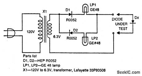
The circuit tests whether or not a diode is open, shorted, or functioning correctly. If lamp A lights, the diode under test is functional. When lamp B is lit, the diode is good but connected backwards. When both lamps are lit, the diode is shamed, and it is open if neither lamp is lit. (View)
View full Circuit Diagram | Comments | Reading(0)
GO/NO_GO_DIODE_TESTER
Published:2009/6/25 20:46:00 Author:May
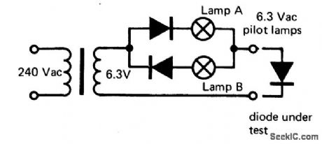
If lamp A or B is illuminated, the diode is serviceable. If both light, the diode is short circuited. If neither light, diode is an open circuit. (View)
View full Circuit Diagram | Comments | Reading(741)
TRANSISTOR_SORTER/TESTER
Published:2009/6/25 20:45:00 Author:May
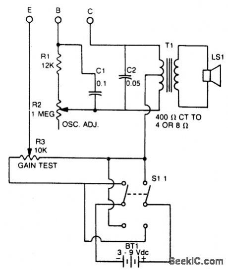
This tester checks transistor for polarity (PNP or NPN). An audible signal will give an indication of gain. Tester can also be used as a GO/NO GO tester to match unmarked devices. (View)
View full Circuit Diagram | Comments | Reading(812)
ZENER_TESTER
Published:2009/6/25 20:44:00 Author:May
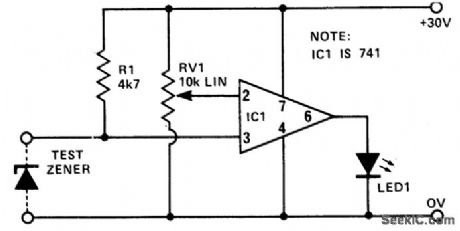
This circuit provides a low cost and reliable method of testing zener diodes. RV1 can be calibrated in volts, so that when LED 1 just lights, the voltage on pins 2 and 3 are nearly equal. Hence, the zener voltage can be readdirectly from the setting of RV1. The supply need only be as high a value as the zener itself.For a more accurate measurement, a precision pot could be added and calibrate (View)
View full Circuit Diagram | Comments | Reading(1184)
_CAPACITANCE_METER
Published:2009/6/25 20:42:00 Author:May
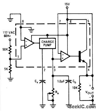
Output voltage is proportional to the capacitance connected to pin 2 of the charge pump. The meter works over a range of 0.01 to 0.1 μF with Ra set at 111 K. Over this range of capacitance, the output voltage varies from 1 to 10 volts with a 15 volt power supply. A constant frequency reference is taken from the 60-Hz line. (View)
View full Circuit Diagram | Comments | Reading(911)
| Pages:72/101 At 206162636465666768697071727374757677787980Under 20 |
Circuit Categories
power supply circuit
Amplifier Circuit
Basic Circuit
LED and Light Circuit
Sensor Circuit
Signal Processing
Electrical Equipment Circuit
Control Circuit
Remote Control Circuit
A/D-D/A Converter Circuit
Audio Circuit
Measuring and Test Circuit
Communication Circuit
Computer-Related Circuit
555 Circuit
Automotive Circuit
Repairing Circuit