
Measuring and Test Circuit
Index 65
F_V_WITH_4151
Published:2009/7/1 20:41:00 Author:May
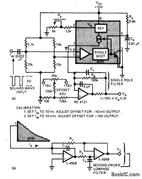
1Uses Raytheon 4151 as frequency-to-voltage converter for generating currentpulses having precise amplitude and width.Average value of output pulse train is directly proportional to input frequency. Article gives design equations. Response time can be improved and ripple reduced by using secondorder (double-pole) low-pass filter as shown in diagram (b). Ripple is Iess than 0.1 V P-P over range of 10 to 10,000Hz when R1 and R2 are 100K and C1 and C2 are 0.1 μF.-T. Cate, IC V/F Converters Readily Handle Other Functions Such as F/ V,A/D, EDN Magazine, Jan. 5, 1977, p 82-86. (View)
View full Circuit Diagram | Comments | Reading(1015)
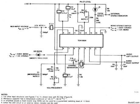
TIME_DIVISION_MULTIPLEX(TDM)STEREO_DECODER
Published:2009/7/1 20:31:00 Author:May
View full Circuit Diagram | Comments | Reading(2703)
PULSE_WIDTH_DETECTOR
Published:2009/7/1 19:52:00 Author:May
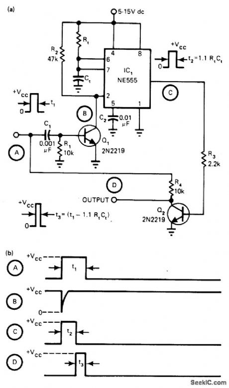
Connections as shown for 555 timer give output only if trigger pulse width is greater than time constant (t2 = 1.1RtCt) of mono MVBR circuit. Q1 is normally off. Pin 2 of 555 is then high. At start of trigger pulse, output at point C is low. Positive trigger drives Q1 on for time determined by R1C1, feeding negative-going pulse to trigger pin 2. Timer then acts as normal mono, driving Q2 on for time t2. If input pulse is still high at end of t2, it appears at output D since Q2 is now off. Output pulse width is thus equal to input trigger width less 1.1RtCt. For greater accuracy, insert delay between point A and R4 equal to inherent propagation delay of timer.-S. Sarpangal, Build a Pulse-Width Detector with a 555 Timer, EDN Magazine, Oct. 5, 1977, p 93 and 96. (View)
View full Circuit Diagram | Comments | Reading(0)
DUAL_TIME_CONSTANT_TONE_DECODER
Published:2009/7/1 20:22:00 Author:May


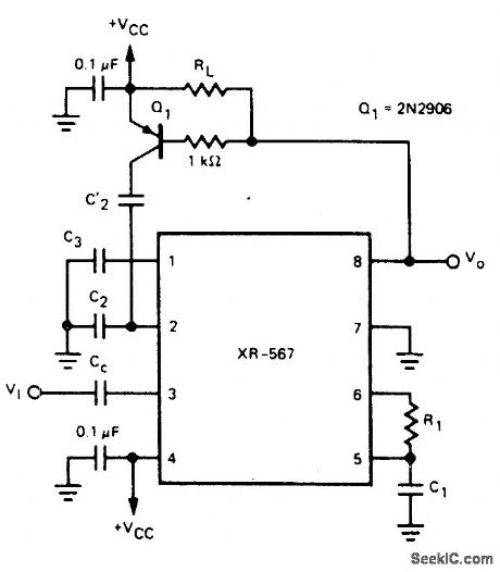
For some applications it is important to have a tone decoder with narrow bandwidth and fast response time. This can be accomplished by the dual time constant tone decoder circuit shown.The circuit has two low-pass loop filter capacitors, C2 and C'2. With no input signal present, the output at pin 8 is high, transistor Q1 is off, and C'2 is switched out of the circuit.Thus, the loop low-pass filter is comprised of C2, which can be kept as small as possible for minimum response time. When an in-band signal is detected, the output at pin 8 will go low, Q1 will turn on, and capacitor C'2 will be switched in parallel with capacitor C2. The low-pass fil-ter capacitance will then be C2 + C'2. The val-ue of C'2 can be quite large in order to achieve narrow bandwidth. During the time that no input signal is being received, the bandwidth is de-termined by capacitor C2. (View)
View full Circuit Diagram | Comments | Reading(0)
HETERODYNE_FREQUENCY_METER_
Published:2009/7/1 20:18:00 Author:May
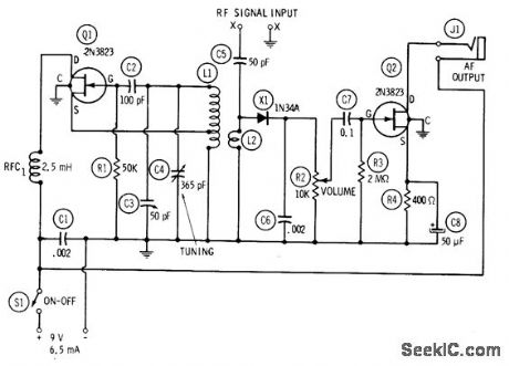
Circuit consists of 1-2 MHz oscillator Q1, untuned mixer X1, and AF beat-note amplifier Q2. C4 is calibrated to read directly in frequency from 1 to 2 MHz, using accurate unmodulated RF signalgenerator. After calibration, unknown RF signal input frequency is fed into meter for zero-beating with harmonics of calibrated oscillator.Magnetic headphones plugged into J1 make beat note audible. On second harmonic, dial of C4 covers 2-4 MHz; on twentieth harmonic, coverage is 20-.40 MHz. L1 is 65 tums No. 28 enamel on 1-inch form, tapped 20 tums from ground. L2 is 10 tums No. 28 enamel closewound around center of L1.-R. P. Turner, FET Circuits, Howard W. Sams, Indianapolis, IN, 1977, 2nd Ed., p 144-146. (View)
View full Circuit Diagram | Comments | Reading(1023)
SPARK_COIL_TACHOMETER_
Published:2009/7/1 20:11:00 Author:May
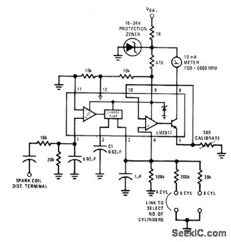
Input to National LM2917 tachometer IC is taken from spark-coil distributor terminal of gasoline engine. Frequency of input signal is converted to voltage for driving meter. Circuit is set up for number of cylinders on engine by adding link for appropriate timing resistor. Zener protects IC from transients found in auto battery circuit.- Linear Applications, Vol. 2, National Semiconductor, Santa Clara, CA, 1976, AN-162, p 9-10. (View)
View full Circuit Diagram | Comments | Reading(1158)
0_10kHz_to_0_10VDC_
Published:2009/7/1 20:06:00 Author:May
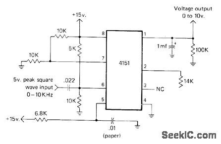
Raytheon 4151VFC voltage-to-frequency converter is used in reverse as linear frequency-to-voltage converter.Applications include use in pairs as complete data transmission system, for remote monitoring of DC voltage such as output of SWR bridge located at junction of antenna with transmission line. DC voltage is changed into audio volt-age at remote location, sent over lines, then changed back to DC at readout location. Line characteristics do not affect frequency of audio signal.-J. J. Schultz, A Voltage-to-Frequency Converter IC with Amateur Applications, CQ, Jan. 1977, p 39-41 and 75. (View)
View full Circuit Diagram | Comments | Reading(2220)
GUARDED_INPUT_PICOAMMETER_CIRCUIT
Published:2009/7/1 4:26:00 Author:May
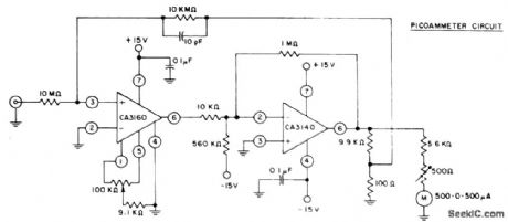
The circuit utilizes CA3160 and CA3140 BiMOS op amps to provide a full-scale meter deflection of ±3 pA. The CA3140 serves as an X100 gain stage to provide the required plus and minus output swing for the meter and feedback network. Terminals 2 and 4 of the CA3160 are at ground potential, thus its input is operated in the guarded mode. (View)
View full Circuit Diagram | Comments | Reading(2155)
STANDBY_GENERATOR_FREQUENCY_METER
Published:2009/7/1 4:19:00 Author:May


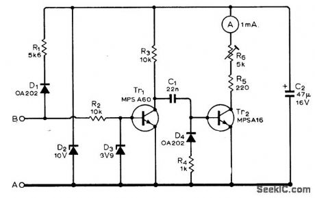
Developed for use with 10-60 VAC generator driven by Iawn mower engine, as guide for adjusting speed manually to give correct power-line frequency. Output of altemator, connected to A and B,is converted to regulated 10VDC by R1, D1, D2, and C2. Same input voltage is squared by Tr1 and fed to Tr 2through differentiating circuit. Current pulses developed in collector circuit of Tr2 have constant width and varying repetition rate depending on input frequency. Inertia of meter movement provides integration required to give steady reading that changes only with input frequency. Meter scale is calibrated from 0 to 100 Hz,with R6 adjusted to give correct reading when 10-60 VAC Iine voltage is applied to input. Power transformer must be used to boost output of alternator to correct AC Iine voltage.-J. M. Caunter,Low-Cost Emergency Power Generator, Wlireless World, Feb. 1975,p 75-77. (View)
View full Circuit Diagram | Comments | Reading(1045)
PICO_AMMETER
Published:2009/7/1 4:12:00 Author:May
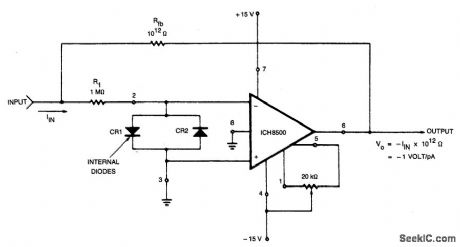
Care must be taken to eliminate any stray currents from flowing into the current summing node. This can be accomplished by forcing all points surrounding the input to the same potential as the input. In this case the potential of the input is at virtual ground, or OV. Therefore, the case of the device is grounded to intercept any stray leakage currents that may otherwise exist between the ±15 V input terminals and the inverting input summing junctions. Feedback capacitance should be kept to a minimum in order to maximize the response time of the circuit to step function input currents. The time constant of the circuit is approximately the produce of the feedback capacitance Cfb times the feedback resistor Rfb, For instance, the time constant of the circuit is 1 sec if Cfb= 1pF. Thus, it takes approximately 5 sec (5 time constants) for the circuit to stabilize to within 1% of its final output voltage after a step function of input current has been applied. Cfb of less than 0.2 to 0.3 pF can be achieved with proper circuit layout. (View)
View full Circuit Diagram | Comments | Reading(0)
DATE_DETECTOR
Published:2009/7/1 4:08:00 Author:May
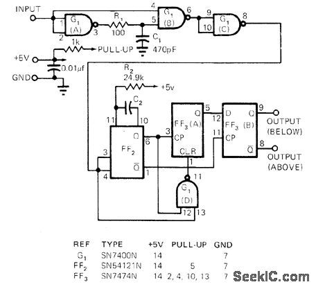
Only three ICs are used to sense pulse rate of input signal with high accuracy,For monitoring frequency, two such circuits can be used, with one set to upper frequency limit and other to lower limit. Output is high when input pulse rate is above set point and low for frequencies below set point. Frequency of set point is reciprocal qf monostable delay time (f0 = 1/0.32R2 C2).-J. W. Poore,Three IC′s Accurately Sense Pulse Rate,EDN Magazine, Aug. 15, 1972, p 53. (View)
View full Circuit Diagram | Comments | Reading(912)
CURRENT_SENSING_IN_suPPLY_RAILS
Published:2009/7/1 4:06:00 Author:May
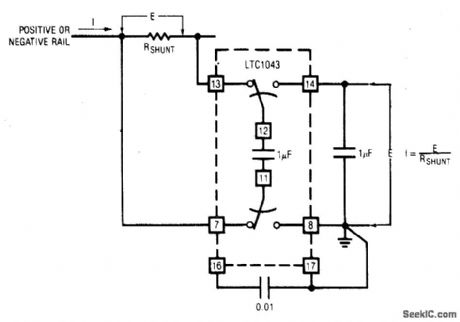
The LTC1043 can sense current through a shunt in either of its supply rails. This capability has wide application in battery and solar-powered systems. If the ground-referred voltage output is unloaded by an amplifier, the shunt can operate with very little voltage drop across it, minimizing losses. (View)
View full Circuit Diagram | Comments | Reading(678)
CRYSTAL_TESTER
Published:2009/7/1 3:57:00 Author:May
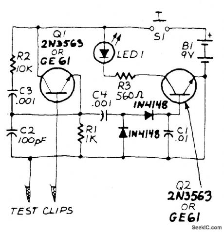
Transistor Q1, a 2N3563, and its associated components form an oscillator circuit that will oscillate if, and only if, a good crystal is connected to the test clips. The output from the oscillator is then rectified by the two 1N4148 diodes and filtered by C1, a.01 μF capacitor.The positive voltage developed across the ca-pacitor is applied to the base of Q2, another 2N3563, causing it to conduct. When that happens, current flows through LED1, causing it to glow. Since only a good crystal will oscillate, a glowing LED indicates that the crystal is indeed Ok. The circuit is powered by a standard nine-volt transistor-radio battery and the SPST pushbutton power-switch is included to prolong battery life. (View)
View full Circuit Diagram | Comments | Reading(0)
TROUBLE_TONE_ALERT
Published:2009/7/1 3:41:00 Author:May
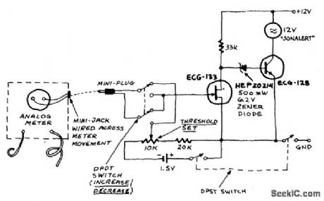
The Trouble Tone Alert is intended for use with analog meters-just wire a mini earphone jack directly across the meter movement, plug it in, and you're all set. This device reacts the to the meter-movement driving voltage. It will respond to a change in ac or dc voltage, current, or in resistance. The circuit will respond to an increase or decrease selected by the DPDT switch and is adjusted with the threshold control until the tone from the Sonalert just disappears (with the meter in the circuit being tested, of course). (View)
View full Circuit Diagram | Comments | Reading(783)
4_h_DIGITAL_WATCH
Published:2009/7/1 3:22:00 Author:May
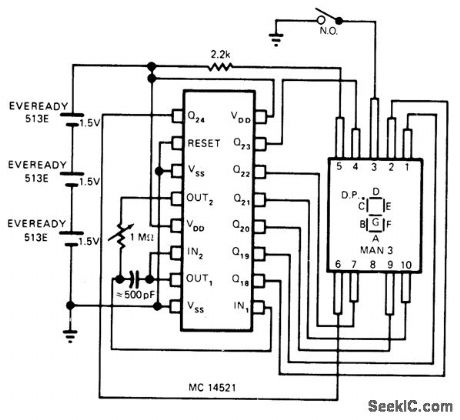
Single Motorola MC14521 CMOS IC drives single-digit MAN 3 LED display in such a way that time range of 4 h is obtained wIth 1.875 min resolution. Can be built into old watch case at cost under $10 for parts.Oscillator frequency of 1.165 kHz can be tweaked to ad just dock, or crystal oscillator can be added for high accuracy. Analog/binary format of readout provides deciphering challenge to user, even though article gives diagram showing which segments of LED are lit for each time reading. Time intenrals represented by each lit segment of display are: B = 2 h; C = 1 h; A = 30 min; F = 15 min; G = 7.5 min; E = 3.75 min; D = 1.875 min.-R. M. Steimle, Small CMOS Digital Watch Has Analog LED Output, EDN Magazine, Aug. 20, 1976, p 86. (View)
View full Circuit Diagram | Comments | Reading(2810)
10_MHz_UNIVERSAL_COUNTER
Published:2009/7/1 3:07:00 Author:May
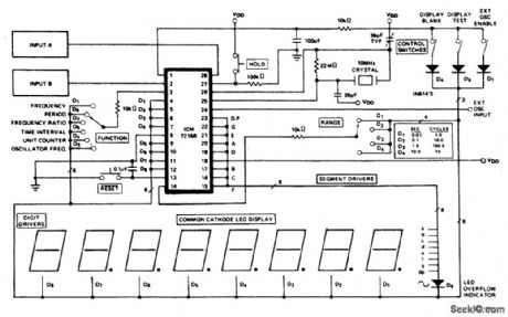
The ICM7216A or B can be used as a minimum component complete Universal Counter.This circuit can use input frequencies up to 10 MHz at INPUT A and 2 MHz at INPUTB If the signal at INPUT A has a very Iow duty cycle it may be necessary to use a 74121 monostable multivibrator or similar circuit to stretch the input pulse width to be able to guarantee that it is at least 50 ns in duration. (View)
View full Circuit Diagram | Comments | Reading(0)
ATTENDANCE_COUNTER
Published:2009/7/1 3:03:00 Author:May
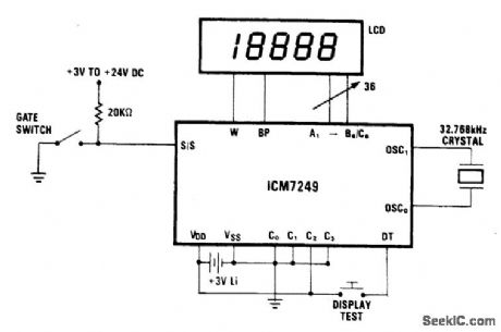
The display shows each increment. By using mode 2, external debouncing of the gate switch is unnecessary, provided the switch bounce is less than 35ms. The 3 V lithium battery can be replaced without disturbing operation if a suitable capacitor is connected in parallel with it. The display should be disconnected, if possible, during the procedure to minimize current drain. The capacitor should be large enough to store charge for the amount of time needed to physically replace the battery (t = VC/1). A 100 μF capacitor initially charged to 3 V will supply a current of 1.0 μA for 50 seconds before its voltage drops to 2.5 V, which is the minimum operating voltage for the ICM7249.Before the battery is removed, the capacitor should be placed in parallel, across the VDD and GND terminals. After the battery is replaced, the capacitor can be removed and the display reconnected. (View)
View full Circuit Diagram | Comments | Reading(0)
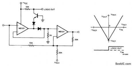
ANALOG_COUNTER_CIRCUIT
Published:2009/7/1 3:01:00 Author:May
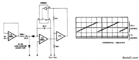
A straightforward circuit using a LM311 for the level detector and a CMOS analog gate to discharge the capacitor is shown. An important property of this type of counter is the ease with which the count can be changed; it is only necessary to change the volt-age at which the comparator trips. A low cost A-D converter can also be designed using the same principle since the digital count between reset periods is directly proportional to the analog voltage used as a reference for the comparator. A considerable amount of hysteresis is used in the comparator. This ensures that the capacitor is completely discharged during the reset period. In a more sophisticated circuit, a dual comparator window detector could be used, the lower trip point is set close to ground to ensure complete discharge. The upper trip point could then be adjusted independently to determine the pulse count.
(View)
View full Circuit Diagram | Comments | Reading(1416)
100_MHz_FREQUENCY,PERIOD_COUNTER
Published:2009/7/1 2:59:00 Author:May
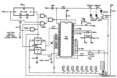
The figure shows the use of a CD4016 analog multiplex to multiplex the digital outputs back to the FUNCTION input. Since the CD4016 is a digitally controlled analog transmission gate, no level shifting of the digit output is required. The CD4051's or CD4052's could also be used to select the proper inputs for the multiplexed input on the ICM7226 from 2 or 3 bit digital inputs. These analog multiplexers may also be used in systems in which the mode of operation is controlled by a microprocessor rather than directly from front panel switches. TTL multiplexors such as the 74LS153 or 74LS251 may also be used, but some additional circuitry will be required to convert the digit output to TTL compatible logic levels. (View)
View full Circuit Diagram | Comments | Reading(4627)
BINARY_COUNTER
Published:2009/7/1 2:55:00 Author:May
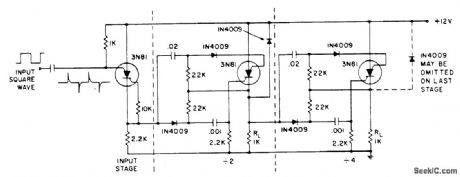
Stages are triggered by the positive going edge. The scs is tumed on at the cathode gate; turned off at the anode gate. The anode-to-cathode IN4009 suppresses positive transients while the scs is recovering. The input stage generates fast positive edges to trigger the counter. (View)
View full Circuit Diagram | Comments | Reading(0)
| Pages:65/101 At 206162636465666768697071727374757677787980Under 20 |
Circuit Categories
power supply circuit
Amplifier Circuit
Basic Circuit
LED and Light Circuit
Sensor Circuit
Signal Processing
Electrical Equipment Circuit
Control Circuit
Remote Control Circuit
A/D-D/A Converter Circuit
Audio Circuit
Measuring and Test Circuit
Communication Circuit
Computer-Related Circuit
555 Circuit
Automotive Circuit
Repairing Circuit