
Measuring and Test Circuit
Index 70
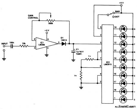
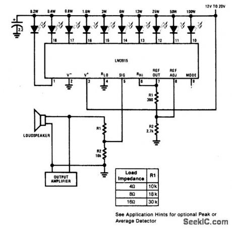
LED_BAR_DOT_LEVEL_METER
Published:2009/6/28 21:18:00 Author:May
Circuit Notes
A simple level of power meter can be arranged to give a bar or dot display for a hi-fi system. Use green LEDs for 0 to 7; yellow for 8 and red for 9 to indicate peak power. The gain control is provided to enable alibration on the equipment with which the unit is used. Because the unit draws some 200 mA, a power supply is advisable instead of running the unit from bat-teries. (View)
View full Circuit Diagram | Comments | Reading(1667)
105_GHz_RADAR_DETECTOR
Published:2009/6/28 21:13:00 Author:May
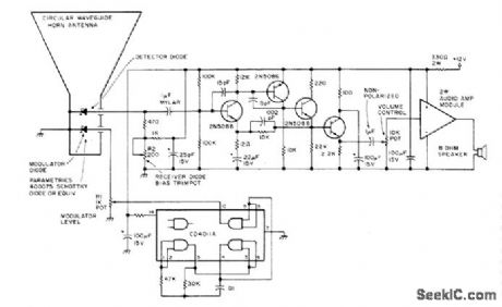
Picks up CW Doppler traffic radar signals in X-band region at 10.525 GHz and alerts speeding driver with audio tone. Article also tells how traffic radars work. By adding 10.5-6Hz oscillator, same cir-cuit can be used in 10.5.GHz amateur radio band for communicating with other cars using this band. Dimensioned diagram of horn is given.-S. M. Olberg, Mobile Smokey Detector, 73 Mag-azine, Holiday issue 1976, p 32-35. (View)
View full Circuit Diagram | Comments | Reading(5276)
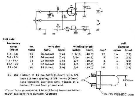
GATE_DIP_METER_COVERS_18_150_MHz
Published:2009/6/28 21:11:00 Author:May
View full Circuit Diagram | Comments | Reading(913)
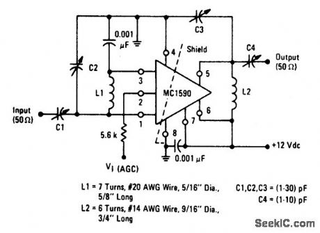
60_MHz_POWER_GAIN_TEST_CIRCUIT
Published:2009/6/28 21:09:00 Author:May
View full Circuit Diagram | Comments | Reading(0)
POWER_METER(1_kW_FULL_SCALE)
Published:2009/6/28 21:09:00 Author:May
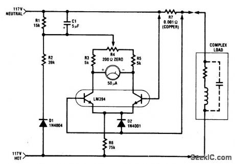
The circuit is intended for 117 Vac ±50 Vac operation, but can be easily modified for higher or lower voltages. It measures true (nonreactive) power be ing delivered to the load and requires no external power supply. Idling power drain is only 0.5 W. Load current sensing voltage is only 10 mV, keeping load voltage loss to 0.01%. Rejection of reactive load currents is better than 100:1 for linear loads. Nonlinearity is about 1% full scale when using a 50 μA meter movement. (View)
View full Circuit Diagram | Comments | Reading(0)
1AUDIO_POWER_METER
Published:2009/6/28 21:07:00 Author:May
View full Circuit Diagram | Comments | Reading(0)
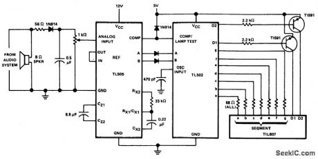
AUDIO_POWER_METER
Published:2009/6/28 21:06:00 Author:May
View full Circuit Diagram | Comments | Reading(0)
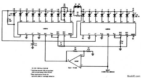
EXTENDED_RANGE_VU_METER(DOT_MODE)
Published:2009/6/28 21:05:00 Author:May
View full Circuit Diagram | Comments | Reading(0)
PHOTOGRAPHIC_TIMER
Published:2009/6/28 21:04:00 Author:May
View full Circuit Diagram | Comments | Reading(0)
SHUTTER_TESTER
Published:2009/6/28 21:03:00 Author:May
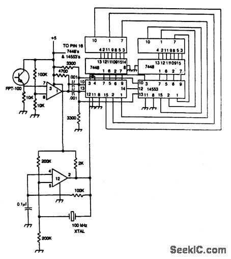
Shutter speed tester combines frequency counter, crystal oscillator, and photo-transistor-operated gate generator. Oscillator pulses are counted as long as the shutter is open. Reset is automatic at the instant the shutter opens.
(View)
View full Circuit Diagram | Comments | Reading(0)
FLASH_EXPOSURE_METER
Published:2009/6/28 21:02:00 Author:May
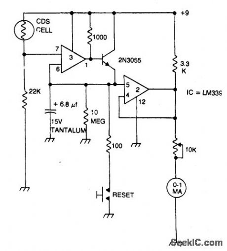
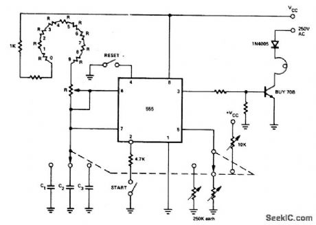
Strobe light meter catches the peak of flash intensity and holds it long enough to give a reading. The reset button must be pressed before each measurement. (View)
View full Circuit Diagram | Comments | Reading(0)
DARKROOM_TIMER
Published:2009/6/28 20:50:00 Author:May
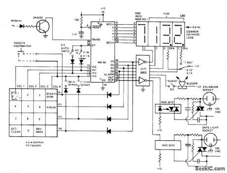
The darkroom timer/controller uses few external components: a display, a digit driver, keyboard, and output switching devices. A 4-digit common-cathode LED display is desirable for dark room environments. The time base is provided by shaping up the 50/60 Hz ac line. A DPDT switch (S1) is used to select a resolution of .1 or 1 seconds and to simultaneously move the decimal point. Timer/ controller has two switched ac outlets, one for the enlarger and one for the safe light. They are the complements of each other in that the safe light is on when the enlarger is not active and is off when the enlarger is printing. The buzzer is of the self-contained oscillator variety and operates with dc drive. (View)
View full Circuit Diagram | Comments | Reading(0)
DIP_METER_USING_N_CHANNEL_IGFET(MOSFET)AND_SEPARATE_DIODE_DETECTOR
Published:2009/6/26 4:46:00 Author:May
View full Circuit Diagram | Comments | Reading(760)
AUDIO_CONTINUITY_TESTER
Published:2009/6/26 4:05:00 Author:May
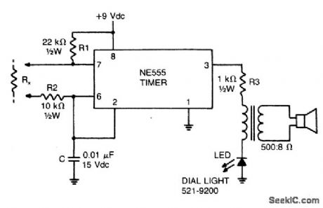
This low-current audio continuity tester indicates the unknown resistance value by the frequency of audio tone. A high tone indicates a low resistance, and a tone of a few pulses per second indicates a resistance as high as 30 megohms. (View)
View full Circuit Diagram | Comments | Reading(0)
LINEAR_SCALE_OHMMETER
Published:2009/6/26 3:55:00 Author:May
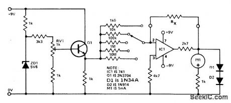


One preset resistor is used for all the ranges, simplifying the setting up. Diode clamping is included to prevent damage to the meter if the unknown resistor is higher than the range selected. When the meter has been assembled, a 10 K precision resistor is placed in the test position, R,; the meter is set to the 10 K range and RV1 is adjusted for full scale deflection. (View)
View full Circuit Diagram | Comments | Reading(2044)
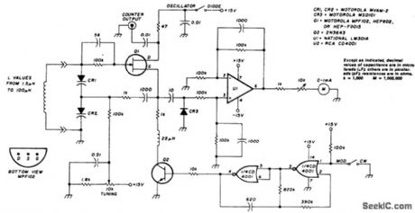
VARICAP_TUNED_FET_DIP_METER_WITH_1_kHz_MODULATION
Published:2009/6/26 3:07:00 Author:May
View full Circuit Diagram | Comments | Reading(1384)
LOGARITHMIC_WATTMETER
Published:2009/6/26 2:59:00 Author:May
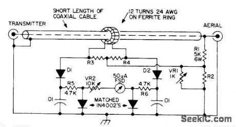
Single meter scale covers 1-1000W, with equally spaced divisions for 1,10,100,and 1000. This log scale makes it possible to measure very low reflected powers and very high forward powers simultaneously with same percentage accuracy.
Basis of operation is that voltage dropped across forward-biased 1N40C2 silicon PN junction diode is proportional to logarithm of cur rent through it. For 50-ohm line, use 220 for R2 and 27 for R3 and R4. For 75 ohm Iine, coffesponding values are 180 and 33. Detectordiodes are point-contact germanium rated at 80 PIV.
Article gives construction details. Ground coax braid at one end only. Ferrite ring is 0.5-inch Mullard FX1596 or equivalent.-P.G.Martin, Some Directional Wattmeters and a Novel SWR Meter, 73Magazine,Aug.1974,p 17,19-21,23-24,and 26. (View)
View full Circuit Diagram | Comments | Reading(0)
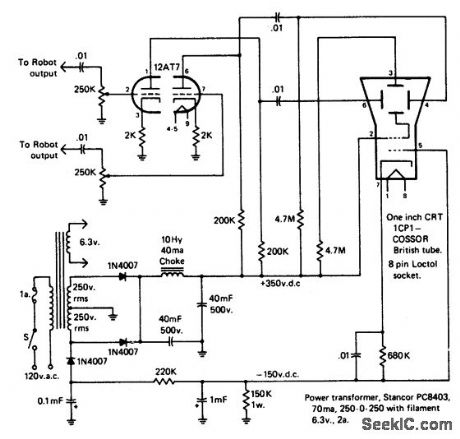
OSCILLOSCOPE_MONITOR
Published:2009/6/26 2:26:00 Author:May
View full Circuit Diagram | Comments | Reading(888)
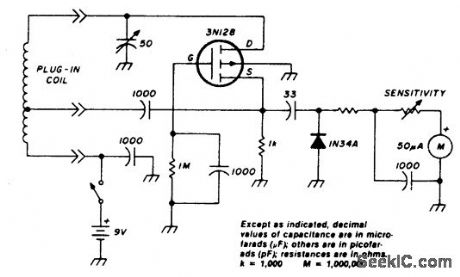
LINEAR_FIELD_STRENGTH_METER
Published:2009/6/26 2:22:00 Author:May
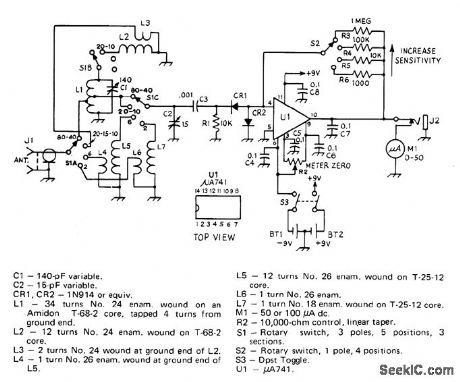
Has sufficient sensitivity for checking antenna patterns and gain while positioned many wavelengths from antenna. Can be used remotely by conlnecting external meter at J2. L1 is tuned by 01 for 80 or 40 meters. For 20, 15, or 10 meters, L2 is switched in parallel with L1. L5 and C2 coverabout 40 to 60 MHz, while L7 and C2 cover 130 to 180 MHz. Band-switched circuits avoid use of plug-in inductors. At most sensitive setting of S2, M1 will detect signals from pickup antenna as weak as 100μV.-L. McCoy, A Linear Field-Strength Meter, QST,Jan.1973,p18-20 and 35. (View)
View full Circuit Diagram | Comments | Reading(787)
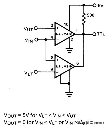
WINDOW_DETECTOR_
Published:2009/6/26 1:57:00 Author:May
View full Circuit Diagram | Comments | Reading(783)
| Pages:70/101 At 206162636465666768697071727374757677787980Under 20 |
Circuit Categories
power supply circuit
Amplifier Circuit
Basic Circuit
LED and Light Circuit
Sensor Circuit
Signal Processing
Electrical Equipment Circuit
Control Circuit
Remote Control Circuit
A/D-D/A Converter Circuit
Audio Circuit
Measuring and Test Circuit
Communication Circuit
Computer-Related Circuit
555 Circuit
Automotive Circuit
Repairing Circuit