
Measuring and Test Circuit
Index 63
TONE_BURST_OSCILLATOR_AND_DECODER
Published:2009/7/2 21:37:00 Author:May
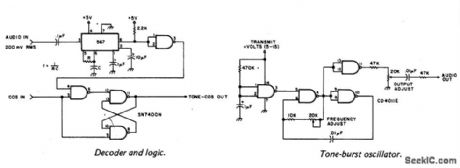
A tone burst sent at the beginning of each transmission is decoded (at receiver) by a PLL causing output from pin 3 of logic gate to turn on carrier-operated switch (COS). (View)
View full Circuit Diagram | Comments | Reading(1080)
AC_MILLIVOLTMETER
Published:2009/7/2 21:10:00 Author:May
View full Circuit Diagram | Comments | Reading(0)
SUPPRESSED_ZERO_METER
Published:2009/7/2 21:08:00 Author:May
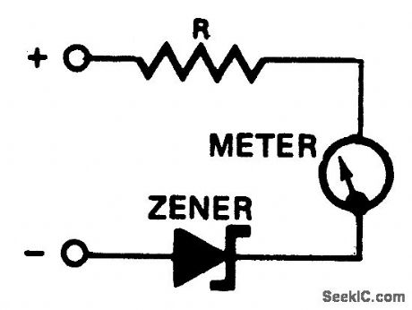
A zener diode placed in series with a voltmeter will prevent the meter from reading until the applied voltage exceeds the zener voltage. Thus, a 10 volt zener in series with a 5-volt meter will allow the condition of a 12 V car battery to be monitored with much greater sensitivity than would be possible with a meter reading 0-15 volts. (View)
View full Circuit Diagram | Comments | Reading(1232)
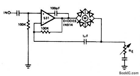
WIDE_BAND_AC_VOLTMETER
Published:2009/7/2 21:05:00 Author:May
This voltmeter is capable of measuring ac signals as low as 15 mV at frequencies from 100 Hz to 500 kHz. Full scale sensitivity may be changed by altering the values R1 through R6 (R=VIN/100 μA). (View)
View full Circuit Diagram | Comments | Reading(2269)
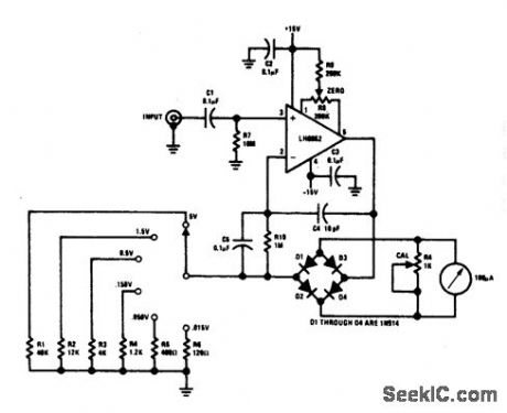
HIGH_INPUT_IMPEDANCE_MILLIVOLTMETER
Published:2009/7/2 21:01:00 Author:May
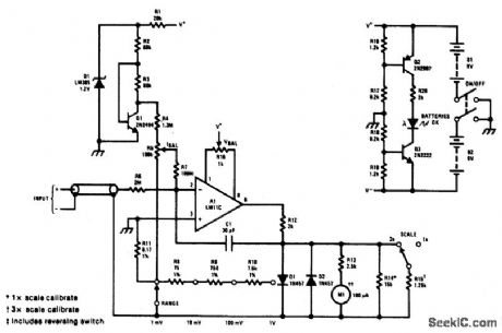
View full Circuit Diagram | Comments | Reading(867)
EXTENDED_RANGE_VU_METER_BAR_MODE
Published:2009/7/2 20:58:00 Author:May
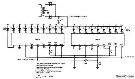
View full Circuit Diagram | Comments | Reading(3060)
TONE_DETECTOR
Published:2009/7/2 20:57:00 Author:May
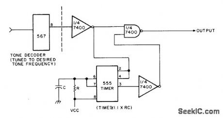
Output goes low only when input tone has been continuous at desired fre quency for interval exceeding duration of pulse from 555 timer. Circuit can be used to reset an alarm system or to detect TTL level that exceeds predetermined time duration.-Circuits, 73 Magazine, April 1977, p 16a. (View)
View full Circuit Diagram | Comments | Reading(0)
SSB_CW_NOISE_LlMlTER
Published:2009/7/2 7:25:00 Author:May

Simple Iimiter is easy to install in receiver having good product detector. In place of dual-diode tube, semiconductor diodes having high front-to-back ratio may be used.-Novice Q & A. 73 Magazine. Holiday issue 1976 p 20. (View)
View full Circuit Diagram | Comments | Reading(756)
AF_NOISE_LlMITER
Published:2009/7/2 7:17:00 Author:May
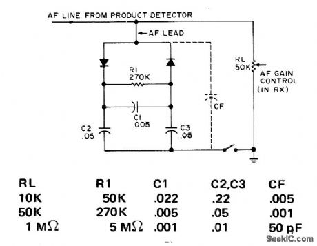
Audio signals rectified by diodes develop bias across R1 and C1 such that diodes are back-biased. Diodes thus conduct and clip only when noise signal peaks exceed bias level.Component values depend on impedance of audio circuit;table gives values for thre common load resistors. Diodes are fast-switching silicon such as 1 N 916. To minimize residual clipping distortion. use value for CF that gives 3-dB rolloff at about 2.5 kHz.-P. Lovelock. The Audio Bishop. 73 Magazine. Sept. 1974. p 75-76 (View)
View full Circuit Diagram | Comments | Reading(811)
SEQUENCE_DETECTOR
Published:2009/7/2 4:04:00 Author:May
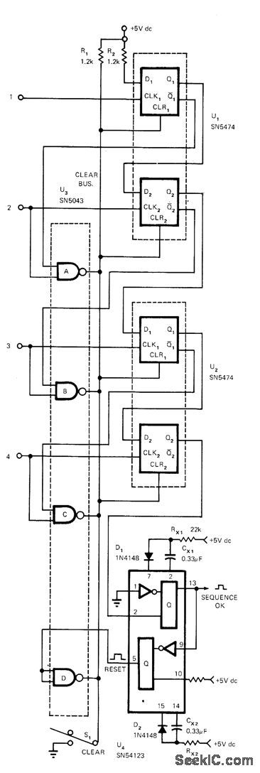
Generates output pulse if, and only if, sequence of input pulses is in prescribed order. Any other sequence inhibits output pulse and clears circuit at instant of first out-of-order pulse. Circuit also clears itself at end of correct sequence, by generating sequence-OK pulse. Developed for use in control systems, electronic combination locks, and any other applications requiring sequence of pulses.To detect more than 4 bits in sequence, NAND gates and flip-flops can be added. If TTL input pulses occur in correct T1-T2-T3-T4 order, 1 state at U1D1 will propagate down chain of D flip-flops until U2Q2 output is reached. Simultaneously, 0 is propagated in similar manner to hold dear bus at 1. Article traces circuit operation in detaiL-M. J. Gallagher, Seff-Clearing Digital Sequence Detector, EDN Magazine, April 5, 1973, p88-89. (View)
View full Circuit Diagram | Comments | Reading(1778)
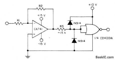
PHASE_SENSITIVE_DETECTOR
Published:2009/7/2 3:57:00 Author:May
Uses quadruple two-input NAND-gate IC with minimum of external components. DC output level is absolutely linear with phase difference at inputs, making circuit suitable for phase-locked loops and phase-shift keyed demodulation. Output is rectangular wave whose mark-space ratio is proportional to phase difference between input square waves. This output is applied to lowpass filter R2-C1, having values chosen to suit operating frequency and required output resistance. R1 is chosen to give required output swing up to maximum of 15 V.-R. A. Harrold, Inexpensive P.S.D., Wireless World, Jan. 1973, p32. (View)
View full Circuit Diagram | Comments | Reading(2732)
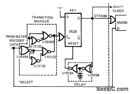
MANCHESTER_CODE_DEMODULATOR
Published:2009/7/2 3:37:00 Author:May
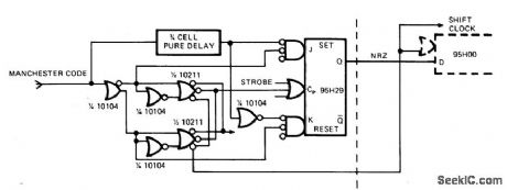
Digital approach using ECL provides maximum speed, isselfsynchronizing for altemate bitpairs, and has minimum complexity. Developed for optically coupled 25-channel PCM telemetry system used over single optical-fiber channel.Undesired transitions in input data are masked by creating strobe. Approach recognizes distinction between identical sequences that would give some output except for time-of-occurrence restriction. Article gives step-by-step design procedure, waveforms, and excitation table.-B. R. Jarrett, Could You Design a High-Speed Manchester-Code Demodulator?,EDN Magazine,Aug.20,1974,p 75-80. (View)
View full Circuit Diagram | Comments | Reading(1177)
IR_DETECTOR
Published:2009/7/2 3:35:00 Author:May
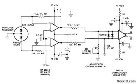
Photodiode transforms light-signal output of fiber-optic cable to electric signal. Spectral response of detector closely matches that of IR-emitting diode at other end of cable, for maximum system efficiency. Rise and fall times of detector can be less than 35 ns when properly biased and loaded by receiver circuit. Developed by Augat, Inc.,Attleboro, MA, as part of fiber-optic evaluation kit for TTL appli cations.-Fiber-Optic Kit Allows Engineering Evaluation of Complete Interconnection System, ComputerDesign, Nov. 1977, p 27 and 30. (View)
View full Circuit Diagram | Comments | Reading(0)
COINCIDENCE_DETECTOR
Published:2009/7/2 3:34:00 Author:May
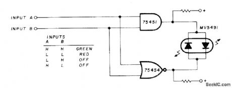
lf inputs A and B are both high, indication will be green. If A and B are both low, indication will be red. If inputs are out of phase, so one is high and the other low, indicator will be off. Suitable for monitoring complex logic circuits, Uses Monsanto MV5491 dual red/green LED, with 220 ohms in upper lead to +5 V supply and 100 ohms in lower +5 V lead because red and green LEDs in parallel back-to-back have different voltage requirements. Drivers are SN75451 and SN75454.-K. Powell, Novel Indicator Circuit, Ham Radio, April 1977, p 60-63. (View)
View full Circuit Diagram | Comments | Reading(0)
AF_NOISE_LIMITER
Published:2009/7/2 3:33:00 Author:May
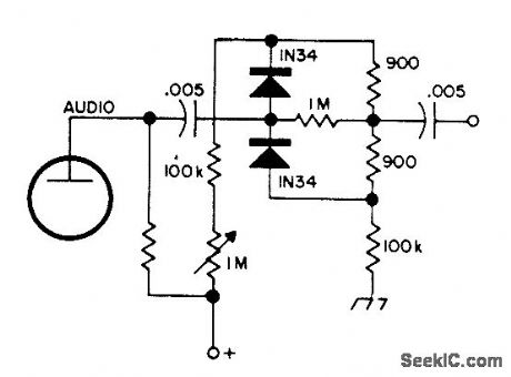
Trough limiter eliminates background noise that is normally passed by conventional limiters. to permit use of higher volume level without annoying static when monitoring single radio channel continuously,-Circuits, 73 Magazine. Dec.1973.p120. (View)
View full Circuit Diagram | Comments | Reading(899)
1_GHz_MANCHESTER_DECODER
Published:2009/7/2 3:31:00 Author:May
Use of ECL flip-flop with toggle rates above 1 GHz makes , decoding of bit rates approaching gigabit speeds feasible. Article gives step-by-step destgn procedure for 48-Mb telemetry application using PCM over single optical-fiber cable.-B.R.Jarrett,Could You Design a High-Speed Manchester-Code Demodulator?, EDN Magazine, Aug. 20, 1974, p 75-80. (View)
View full Circuit Diagram | Comments | Reading(2057)
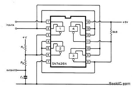
INPUT_NOISE_TEST_CIRCUIT
Published:2009/7/2 3:20:00 Author:May
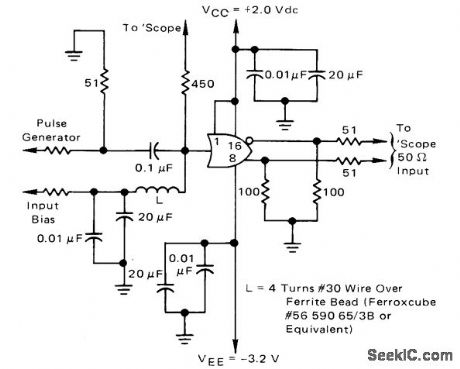
Used for mealsuring noise immunity of emitter-coupled logic to transient signal on input line. Supply voltages used permit terminating logic outputs to ground through 50-ohm CRO probe. Accurate bias provided by power supply is used to set input logic levels. 450-ohm resistor is used in series with 50-ohm input of CRO to isolate input; this gives 10:1 amplitude attenuation while still providing accurate picture of input noise.-B. Blood. AC Noise Immunity of MECL 10.000 lntegrated Circuits. Motorola, Phoenix. AZ. 1972, AN-592. (View)
View full Circuit Diagram | Comments | Reading(827)
LF_OR_HF_FIELD_STRENGTH_METER
Published:2009/7/2 2:14:00 Author:May
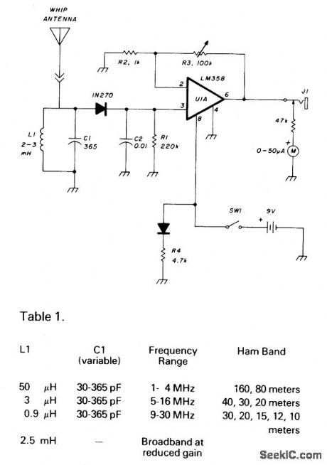
C1 and L1 resonate on the 1750 meter band, with coverage from 150 kHz to 500 kHz. L1 can be slug-tuned for 160-to-190 kHz coverage alone or a 2.5 mH choke can be used for L1, if desired, using C1 for tuning. A 1N270 germanium diode rectifies the RE signal and C2 is charged at the peak RF level. This dc level is amplified by an LM358.The gain is determined by R2 and R3, 1 100-kilohm linear potentiometer that varies the dc gain from 1 to 100, driving the 50 microampere meter. This field strength meter need not be limited to LF use. The Table shows the L1 and C1 values for HF operation and broadband operation. (View)
View full Circuit Diagram | Comments | Reading(1636)
HIGH_SENSITIVITY_FIELD_STRENGTH_METER
Published:2009/7/2 2:07:00 Author:May
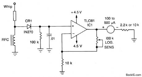
A TL081 (IC1 op amp is used to increase sensitivity. RF signal is detected by CR1 and is then amplified by IC1. Full-scale sensitivity is set with the 100 K potentiometer. (View)
View full Circuit Diagram | Comments | Reading(1258)
FIELD_STRENGTH_METER_II
Published:2009/7/1 23:53:00 Author:May
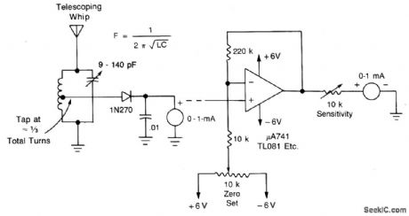
Minimum-parts field-strength meter is shown here. For more distant testing, add the dc amplifier. (View)
View full Circuit Diagram | Comments | Reading(1356)
| Pages:63/101 At 206162636465666768697071727374757677787980Under 20 |
Circuit Categories
power supply circuit
Amplifier Circuit
Basic Circuit
LED and Light Circuit
Sensor Circuit
Signal Processing
Electrical Equipment Circuit
Control Circuit
Remote Control Circuit
A/D-D/A Converter Circuit
Audio Circuit
Measuring and Test Circuit
Communication Circuit
Computer-Related Circuit
555 Circuit
Automotive Circuit
Repairing Circuit