
Audio Circuit
Index 41
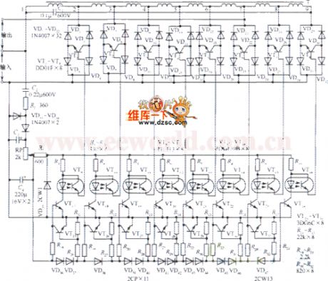
The 110~380V AC auto regulated power supply circuit
Published:2011/6/24 3:37:00 Author:Seven | Keyword: AC, power supply
View full Circuit Diagram | Comments | Reading(891)
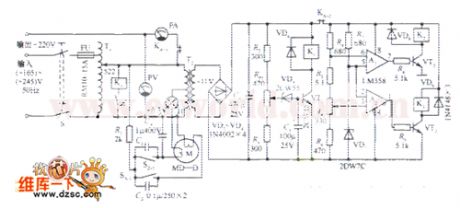
The full-automation AC regulated power supply circuit
Published:2011/6/24 3:42:00 Author:Seven | Keyword: full-automation, power supply
View full Circuit Diagram | Comments | Reading(886)
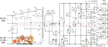
The full-automation AC regulator circuit
Published:2011/6/24 3:55:00 Author:Seven | Keyword: AC regulator, full-automation
View full Circuit Diagram | Comments | Reading(691)
The fridge auto deodorizer circuit
Published:2011/6/24 7:22:00 Author:Seven | Keyword: fridge, auto deodorizer

Working principles The equipment consists of the light control, time delay circuit and the passive ion generator. The equipment is controlled by the fridge internal lighting lamp. When the door is open, the lamps are on, and the LED VT1 is conducting, the 2-pin of the time-base circuit IC1 is in a low LEV immediately, the 3-pin is outputting a high LEV quickly, the dual-way controllable silicon VS is triggered and conducting, and the passive ion generator is stating to work. The working voltage of the light control and time delay control circuit is generated after the 220V AC voltage is stepped down by C1, rectified by VD1, stabilized by VDW and filtered by C2.
(View)
View full Circuit Diagram | Comments | Reading(1682)
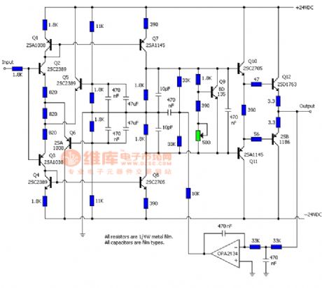
Preamplifier and post amplifier circuit
Published:2011/6/19 10:39:00 Author:John | Keyword: Preamplifier, post amplifier

It is always justified to use an amplifier in the double-balanced mixer circuit. Pre-amp can be more sensitive to the input. When an amplifier (post amplifier) is connected into the passive double-balanced mixer output, it can compensate a loss of 5 ~ 8dB for the passive double-balanced mixer. No matter what, the amplifier can provide a certain amount of isolation for either input or output of the double balanced mixer. The impact caused by the double-balanced mixer from the source or fluctuations in load impedance can be in the liberation. In this case, the amplifier is known as a buffer amplifier.
(View)
View full Circuit Diagram | Comments | Reading(1069)
12V power supply 30W-50W subwoofer circuit
Published:2011/6/21 0:09:00 Author:John | Keyword: subwoofer
12V power supply 30W-50W subwoofer circuit is shown.
(View)
View full Circuit Diagram | Comments | Reading(3718)
Audio preamplifier circuit
Published:2011/6/16 6:25:00 Author:John | Keyword: Audio preamplifier
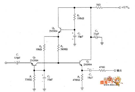
The following figure shows the audio preamplifier matched with 50Ω, which is an improved version of Lawellen circuit. Just as Campbell said, the gain of this circuit is about 40dB and noise value is about 5dB. And the range of input signals has no intention to disturbances (10nV ~ 10mV). These specifications make it available as the amplifier matched with DBM. Just as Lawellen’s circuit, Campbell also uses circuit with the grounded-base input amplifier (Q1) and active isolators (Q2). Beside, an emitter follower / buffer amplifier (Q3) is added.
(View)
View full Circuit Diagram | Comments | Reading(1411)
The multi-function radio principle circuit
Published:2011/6/17 0:26:00 Author:Seven | Keyword: multi-function radio
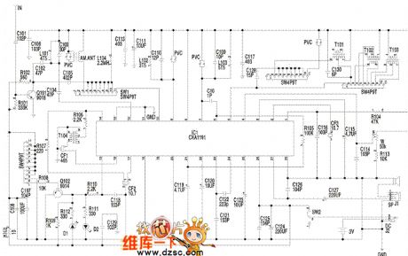
Notes: the audio signal which is output from 23-pin of u1 is coupled by C123 and input from 24-pin. W1 is the electric sound volume control potentiometer, which controls the sound volume of 4-pin of u1. The output audio signal of 23-pin of u1 is sent to the IC internal power amplifier of 24-pin of c1, after being amplified, the audio signal is output from 27-pin to drive the loudspeaker or headphone. The clock control and drive display circuit consists of the LED screen (ICD), SC361O, x1, c1, c6, R1-R5, swl-SW8, Q1 and other elements. (View)
View full Circuit Diagram | Comments | Reading(1059)
The color diagram of the headphone circuit
Published:2011/6/17 0:30:00 Author:Seven | Keyword: color diagram, headphone circuit
View full Circuit Diagram | Comments | Reading(778)
The stereo drive circuit
Published:2011/6/17 0:44:00 Author:Seven | Keyword: stereo drive circuit

The preset amplifier has a low impedance and it is designed to drive long cables, which allows people to listen to the music far away without expensive selective cables. It has an impedance of 16Ω at 1KHz, which makes it connects witch the ordinary ring wires, loudspeakers or alarm cables. It needs a pre-amplifier near the distant music source, such as a disc player, and then people go to a wanted distant place to listen to the music. The receiver point No. of the pre-amplifier is sometimes less than one.
(View)
View full Circuit Diagram | Comments | Reading(756)
The 555 light-off reminder principle circuit
Published:2011/6/17 1:04:00 Author:Seven | Keyword: light-off reminder, principle circuit
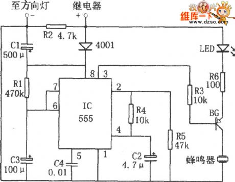
When the light is on, the power supply from the direction light relay is imposed on 555 8-pin, which makes the capacitor C3 charges by R1. As the charging is going on, the LEV on 6-pin is rising, when the LEV reaches 2/3VDD (after it is delayed about 1min), the 555 is reversing, 3-pin outputs a low LEV to make BG conducting. Then the LED is driven to glow, the buzzer is ringing, and the photo-sound reminds the driver of turning off the light quickly. The time of lighting, which is corresponding to the delayed time in the circuit, can be changed by adjusting the time constant R1C3. (View)
View full Circuit Diagram | Comments | Reading(777)
The CIC2851E fridge door closure reminder circuit principle diagram
Published:2011/6/19 0:06:00 Author:Seven | Keyword: fridge door, closure reminder
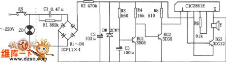
The CIC2851E fridge door closure reminder circuit principleThe circuit consists of the step-down rectifier stable voltage, the time delay circuit, the music integrated circuit CIC2851E, the loudspeaker and so on, of which the step-down rectifier circuit provide with a 3V DC voltage for the whole circuit.When the fridge door is open, the switch AN is on, capacitor C3 is charged by R3, as the charge is going on, the basic pole LEV of BG1 is rising, in about 20min, the voltage on C3 conducts BG1, and BG2 is blocked, which triggers CIC2851E, the output music signal is magnified by BG3.
(View)
View full Circuit Diagram | Comments | Reading(893)
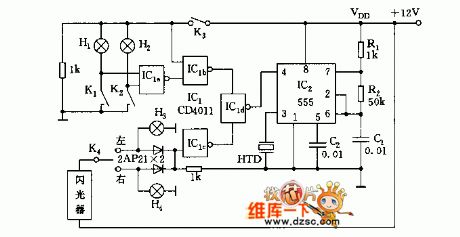
The car alarm circuit
Published:2011/6/17 1:05:00 Author:Seven | Keyword: alarm circuit
View full Circuit Diagram | Comments | Reading(920)
The bus station series indicator circuit
Published:2011/6/18 23:54:00 Author:Seven | Keyword: bus station, indicator
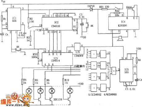
The circuit consists of the 555 single stable time delay circuit, a counter IC2, a decoding displayer IC3, a delay stereo circuit and so on. The single stable circuit consists of 555, Rt, Ct and so on, it's delayed time is td1=1.1RtCt. The counter can preset a 4-bit binary reversible counter CD4516. IC3 is a 4-bit lock-storage 4-16 line decoder. The stereo circuit consists of the music integrated circuit IC4(KD9300) and the loudspeaker. When the switch AN is pressed, the delaying pulse, which is output by IC1, is added on the counter IC2, and IC2 does the +1(or -1) counting, and the output of Q1~Q4 comes into IC3 for decoding. (View)
View full Circuit Diagram | Comments | Reading(1014)
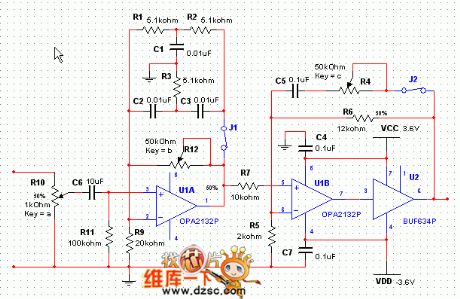
The audio power amplifier circuit of OPA604
Published:2011/6/17 1:18:00 Author:Seven | Keyword: power amplifier
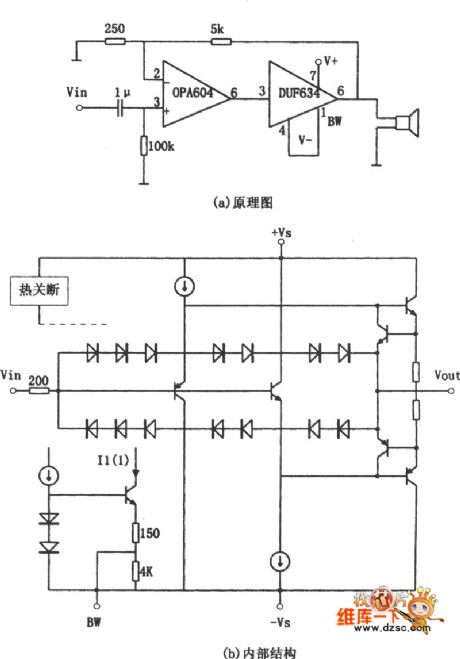
The front stage of the circuit is made of the FET HF op-amp OPA604, the rear stage is made of the high speed buffer BUF634, and a voltage serial passive feedback is used between the two stages of the amplifiers. The magnified multiple of the circuit is determined by two resistors (5kΩ and 250Ω) in the feedback sub-circuit, whose value is l+5kΩ/50Ω≈21. BUF634 is a high speed buffer. (View)
View full Circuit Diagram | Comments | Reading(1643)
The TC9153AP audio control circuit
Published:2011/6/20 22:02:00 Author:Seven | Keyword: audio control circuit
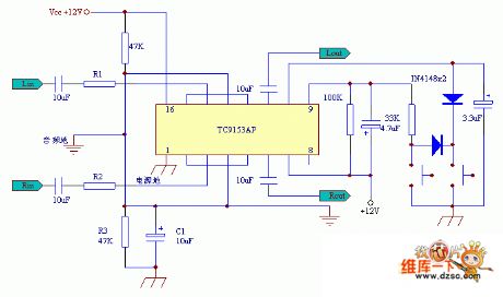
The TC9153AP audio control circuit is shown in the above figure.
(View)
View full Circuit Diagram | Comments | Reading(5036)
The low-noise ECC83 headphone amplifier circuit and el84 valve
Published:2011/6/22 1:48:00 Author:Borg | Keyword: low-noise, headphone amplifier
View full Circuit Diagram | Comments | Reading(3342)
The AT-HA2002 amp audio part principle circuit
Published:2011/6/21 10:04:00 Author:Borg | Keyword: amp, audio part, principle circuit
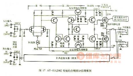
Figure 17. The AT-HA2002 amp audio part principle circuit (View)
View full Circuit Diagram | Comments | Reading(1777)
HA1377--the audio power amplifier circuit
Published:2011/6/23 19:44:00 Author:Seven | Keyword: audio power, amplifier
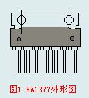
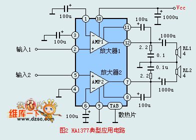
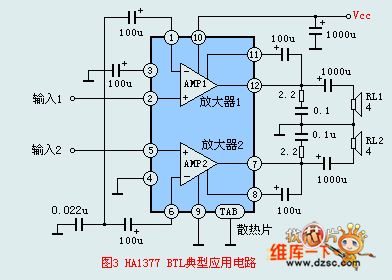
HA1377 is an audio power amplifier circuit produced by Hitachi, there are two teams of amplifier circuits on a silicon chip, the circuit has a big output power, when the voltage is 13.2v and the 4Ω loading is THD=10%, the output power is 5.8W. When TBL is connected, a power of 17W can be got under the above conditions. The circuit is used in portable, desk single channel and stereo dual-channel recorders, etc, the circuit can be in 12-pin single in-line plastic package, the outline is shown in Figure 1.The circuit features:1.the distortion is small.
(View)
View full Circuit Diagram | Comments | Reading(2993)
BA536--The 4.5W dual-channel power amplifier circuit
Published:2011/6/20 20:02:00 Author:Seven | Keyword: dual-channel, power amplifier
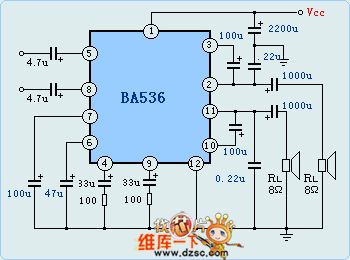
BA536 is a dual-channel power amplifier circuit, which characterizes good balance and little gain difference, the circuit is in 12-pin DIP in-line package, the features of the circuits are as follows. The output powers of each channel are 4.5w(when the loading impedance is 4Ω and the voltage of the power supply is 12v ) and 5.5W(when the loading impedance is 3Ω and the voltage of the power supply is 12v ). The wave rejection rate is 55dB, the distortion is THD=1.5% (when Po=0.5W), the crosstalk is lower than 57dB, the working voltage is 5-12v, which can compose a BTL easily. The limit parameter: Vcc=18V, power consumption: working temperature: -20-75℃.
(View)
View full Circuit Diagram | Comments | Reading(2851)
| Pages:41/54 At 204142434445464748495051525354 |
Circuit Categories
power supply circuit
Amplifier Circuit
Basic Circuit
LED and Light Circuit
Sensor Circuit
Signal Processing
Electrical Equipment Circuit
Control Circuit
Remote Control Circuit
A/D-D/A Converter Circuit
Audio Circuit
Measuring and Test Circuit
Communication Circuit
Computer-Related Circuit
555 Circuit
Automotive Circuit
Repairing Circuit