
Audio Circuit
Index 48
Sample Hold Circuit
Published:2011/5/6 2:55:00 Author:Sue | Keyword: Sample, Hold
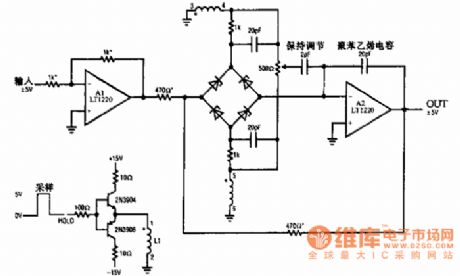
Application: It is used in data acquisition circuit and A/D converting circuit.
(View)
View full Circuit Diagram | Comments | Reading(11)
555 Monostable Trigger Circuit
Published:2011/5/6 2:23:00 Author:Sue | Keyword: Monostable, Trigger
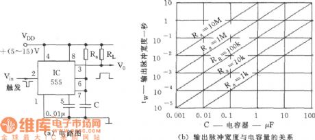
(a) Circuit
(b) Relation between output pulse width and capacitance (View)
View full Circuit Diagram | Comments | Reading(829)
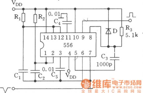
Large Range Variable Duty Ratio Square Wave Generator Circuit
Published:2011/5/6 2:38:00 Author:Sue | Keyword: Large Range, Variable, Duty Ratio, Square Wave, Generator
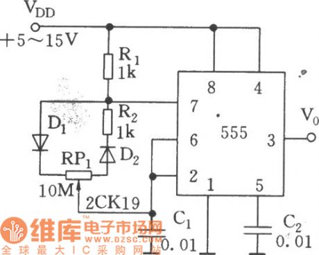
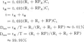
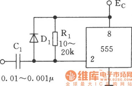
As seen in the figure, 555 and R1,R2,RP1,D1,D2,C1 constitute a astable multivibrator. D1 and D2 serve as guide tubes for charge/discharge circuit.
We can se from the formula above that, no matter how RP1 varies, it has no influence on oscillation period T. The oscillation frequency shown in the figure is about 20Hz. (View)
View full Circuit Diagram | Comments | Reading(1056)
Differential Triggering 555 Circuit
Published:2011/5/6 2:25:00 Author:Sue | Keyword: Differential, Triggering
View full Circuit Diagram | Comments | Reading(753)
The figure of TA7766F low voltage stereo coding integrated circuit
Published:2011/4/22 1:56:00 Author:Crystal Liu | Keyword: low voltage, stereo, coding integrated circuit
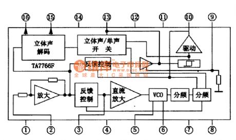
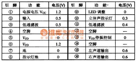
TA7766F low voltage stereocoding integrated circuit is produced by TOSHIBA.1.The internal circuit figure and the pin functions of TA7766F.The integrated package of TA7766F contains amplifying circuit,stereo\single track switch;The circuit of stereo Decoding ,Voltage controlled oscillator circuit,frequency dividing circuit,direct current amplifier and stereo indicator light controller.The integrated blocks within circuit is shown in figure 1.This lC adopt double row flat 16 feet, the integrated circuit encapsulation structure of pin function and data listed see table 1.
2.TA7766F main electric parameters.TA7766F work power voltage range of integrated circuit for 0.9-2V,typical working voltage is 1.5 V.Its ultimate conditions of use in Ta = 25 ℃, the power supply voltage, allow the Vcc = 2V PD = 35OmW, indicator power drive current I (LAMP)5mA .
3.TA7766F typical application circuit.
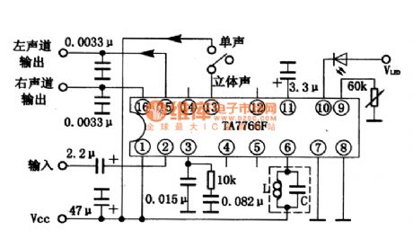
The typical application of manifold blocks TA7766F circuit shown in figure 2.4.Circuit working process.
From TA7766F (2) composite signal input, demodulation of feet after about from (15) channels signal, (16) feet, output, send the latter stage circuit. ⑩ feet external stereo instructions light-emitting diodes that the light emitting diode feet wide by 9 sensitivity resistance can be adjusted. The voltage controlled oscillation in circuit Vco) circuit (by 6 feet external LC resonant circuit can fine-tune Vco frequency.5. Breakdown maintenance tips
When couldn't receive FM stereo programs, and can only receive FM mono programs, stereo indicator light point not bright, but check TA7766F (11) feet wide capacitance, because without short-circuit failure feet (11) if because of capacitance, the yi short-circuit grounding. Stop vibration, stereo decoding circuit doesn't work. Then check (13) feet ChanSheng/stereo conversion switch, if switch can't switch to stereo position, (13) foot has high potentials and Vco also stop vibration without stereo. Step 3 check 6 feet of LC network, when capacitance normal, the radio to the stereo position, re-adjusted L, observe whether indicator lights. Stereo sound If it is not bright and check without problems, then, luminous tube TA7766F measured again all the pins voltage and listed in table 1, comparing the normal whether judge this lC failure. Such as voltage, and check deviation is a deviation feet peripheral components are TA7766F communicqtion problem, then explaining damage.
(View)
View full Circuit Diagram | Comments | Reading(1016)
Time Base Trigger Circuit
Published:2011/5/6 1:11:00 Author:Sue | Keyword: Time Base, Trigger
View full Circuit Diagram | Comments | Reading(867)
6n11 electron tube power amplifier production of information circuit diagram
Published:2011/4/12 9:11:00 Author:Nicole | Keyword: electron tube

The circuit structure of tube preamp have many forms, this preamp adopts improved SRPP circuit + cathode output circuit, shown in Figure 1. Because the SRPP circuit has the features of minimal distortion, wide frequency response and low noise.
The circuit with low output resistance is very popular, the SNR of improved SRPP circuit can improve about 20dB than before, the highest SNR of general SRPP circuit is only 60dB, and the improved SRPP circuit can reach 80dB. Its form voltage gain and resistance capacity coupled amplifier are about the same, dynamic is also nearly the same, electric efficiency is not high, but it is suit for CD and some large dynamic range signal sources, it can be used as input stage, because the efficiency of SRPP circuit is not high, so it adds a first level cathode loaded amplifier, the cathode loaded amplifier has characteristics of low output resistance, bandwidth, low distortion, and it is easy to push any backward stage amplifier.
(View)
View full Circuit Diagram | Comments | Reading(4904)
6sn7 electron tube preamp line circuit diagram
Published:2011/4/17 7:29:00 Author:Nicole | Keyword: electron tube, preamp line
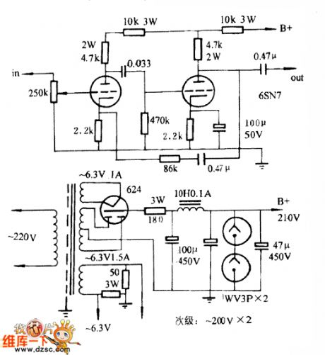
Used 6SN7 as preamp amplification circuit with negative feedback, the figure is as below. It uses 6S8P electron tube of the dawn in this circuit, high voltage power supply adopts 6Z4 as rectifier, and uses two inflatable tubes as voltage regulator, the filament is AC powered, but the filament ground adopts arms resistance balance method to reduce the communication noise.
This circuit is very easy to make, the characteristics of sound is its first class thick and smooth of mediant, but the power is normal and the sound field is weak, it’s unkown whether the intermediate frequency’s performance is too excellent to overshadowed the high and low frequency, its frequency domain extension, dynamics and transient state are not very overstanding, the timbre seems like classic LS3/5A. From the side of Hi-fi, its sound effect is not complete, but it is also pleasurable, especially when we are playing the violin stringed music and person's voice, it is quite satisfying. If this circuit uses the electron tube of the Former Soviet Union’ 6H8C or the US GE’ 6SN7, its power and sound field' analysis can be improved, but the 6SN7 which was made by GE in the 70s is not better than 6H8C in the sound’s smooth, unless we can find the products which are produced in the 60s. Compared to the 6N11 first level cathamplifier and the next SRPP 6N10 preceding stage, its individuality is higher, the medium frequency band is excellent for people auditory impression.
(View)
View full Circuit Diagram | Comments | Reading(13602)
6N10 SRPP preamplifier circuit diagram
Published:2011/4/8 2:42:00 Author:Nicole | Keyword: preamplifier, SRPP
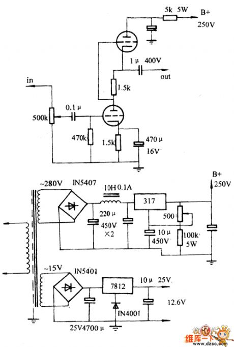
The third preamp uses 6N10 as SRPP circuit, As shown in the figure, this circuit is wide spread, at present, I believe many readers have welded, SRPP is called Shunt Regulator Push-Pull, this circuit has the advantages of excellent linearity, low distortion, high magnification, high dynamic and low output impedance and so on, The performance are better than ordinary typical circuit of common cathode interconnect RC or the last stage as cathode follower, it is in accordance with the conditions of an ideal preamp.
The principle of SRPP is a transistor as the common cathode grounded to enlarge in the below, the gain depends on the anode impedance, most are happened on the top of the transistor, while the upper transistor is a current source, as the changes active load of the following transistor. In addition, the above transistor also can be used as a cathode follower coupler, the signal is outputed to the above transistor grid by the below transistor screen.
(View)
View full Circuit Diagram | Comments | Reading(4264)
Principle Circuit of Digital Amplifier
Published:2011/5/5 9:52:00 Author:Felicity | Keyword: Principle, Digital Amplifier,
The picture above shows the Principle Circuit of Digital Amplifier. (View)
View full Circuit Diagram | Comments | Reading(1012)
Audio frequency selection amplifier circuit compose of SA610ET
Published:2011/5/5 21:45:00 Author:TaoXi | Keyword: Audio, frequency selection
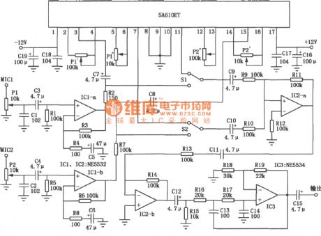
The Audio frequency selection amplifier circuit compose of SA610ET is as shown in the figure. (View)
View full Circuit Diagram | Comments | Reading(1173)
Medium wave AM radio circuit compose of SL34 and SL315
Published:2011/5/5 21:25:00 Author:TaoXi | Keyword: Medium wave, AM radio
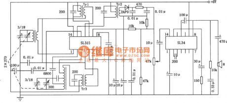
The SL33/34 is designed as the low voltage integrated audio power amplifier, this device has the features of low distortion and Low power consumption, the complete radio circuit is composed of the SL315 integrated frequency conversion intermediate amplification circuit and the SL33/34. The medium wave AM radio circuit compose of SL34 and SL315 is as shown in the figure. (View)
View full Circuit Diagram | Comments | Reading(1077)
170W power amplifier circuit composed of the LM4561 and LM4562
Published:2011/5/5 20:55:00 Author:TaoXi | Keyword: 170W, power amplifier
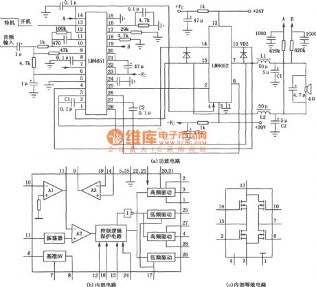
The 170W power amplifier circuit with 4Ω load is as shown in figure (a);
LM4651 is the front circuit of the D class amplifier, it is in the 28-pin DIP package, and the internal equivalent circuit is as shown in figure (c); (View)
View full Circuit Diagram | Comments | Reading(2328)
VCA electronic attenuation circuit
Published:2011/5/5 20:50:00 Author:TaoXi | Keyword: electronic attenuation
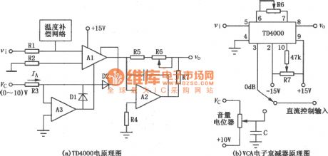
The voltage-controlled amplifier's (VCA) gain is controlled by the voltage, this device can be used in the applications of radio tuner control, automatic audio control, instrumentation preamplifier control, computer acquisition system control, also it can be used as the pulse modulator, the phase detector, the wave filter and the high-precision multiplier.etc.
Circuit of the TD4000 is as shown in figure (a);
The VCA electronic attenuation circuit is shown in the figure (b), it is an application. When the VCA is used as the electronic attenuator, it's features are better than the mechanical attenuator of the chinese broadcasting system, because it does not has the slip noise, easy to control and the attenuation change is continuous. When you adjust the volume manually, the volume potentiometer only need to use the linear potentiometer with Bell characteristics, even if there is noise in the process of using, you can clear the noise by filter. (View)
View full Circuit Diagram | Comments | Reading(2710)
MN67730MH digital DVD audio decoding integrated circuit
Published:2011/5/5 21:49:00 Author:Sharon | Keyword: MN67730MH, digital DVD, audio decoding, integrated
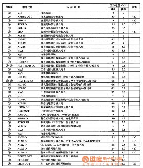
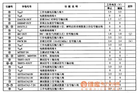
MN67730MH IC pin functions and data
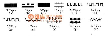
MN67730 IC critical pin wave
MN67730MH is a digital DVD audio decoding integrated circuit produced by Panasonic andwidely used in DVD player movement of Panasonic movement series .
1. Features:MN67730MH integrated circuit includes MPEG-1 decoding circuit, MPEG-2 decoding circuit, AC-3 decoding circuit, linear PCM decoding circuit, constant voltage circuit, clock oscillation circuit, microprocessor interface data bus circuits and other ancillary circuitry.2. IC pin functions and data: MN67730MH integrated circuit is sealed in Quartet 80-pin package. The pin functions and data is listed in the Table, and the critical pin waveform is shown in the figure. (View)
View full Circuit Diagram | Comments | Reading(1064)
Kara OK Tone Circuit
Published:2011/5/4 9:27:00 Author:TaoXi | Keyword: Kara OK Tone
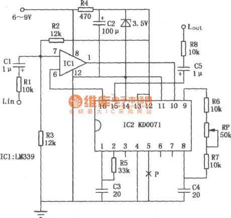
When we using Kara OK to enjoy ourselves, the singer always can't keep up the tunes because of the accompaniment tunes too high or too low. If we install this circuit in the Kara OK machine, so we can easily keep up the tunes. The figure is as shown, theinput signal from the terminal Lin is sendto the 7-pin of ICI voltage comparator, then the signal from 1-pin of ICI send to the 10-pin of the IC2 voice modulation integrated circuit (KD0071).At this moment, one signal return to ICl to compare with the input signal. Another signal send out by the pin-15 of IC2, and connect to the back-stage power amplifier. By adjusting the potentiometer RP between pin-8 and pin-9 of IC2, we can change the oscillation frequency of the circuit, then change the tone of output signal to produce modulation effect. When we are debugging,we need toplace the potentiometer RP in the middle of resistance, then adjust the resistance of resistor R6, R7, turn on/off the ground wire of P point (pin-5 IC2). If the potentiometer RP's resistance decreases, Tone will be low; If the potentiometer RP's resistance increases, Tone will be high.
(View)
View full Circuit Diagram | Comments | Reading(837)
light off reminder circuit composed of 555
Published:2011/5/4 9:28:00 Author:TaoXi | Keyword: light off, remind
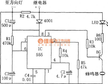
The light off reminder circuit composed of 555 is as shown. This circuit is composed of the monostable delay circuit, drive circuit, buzzer, LED.etc. The output signal of the monostable delay circuit which is composed of the 555 and R1、C3 control the other circuits.
After turned on the light, power of the direction light relay adds to the pin-8 of 555 by diode, so the capacitor C3 is charged by R1. Pin-6's electric potential increases, when the pin-6's electric potential increases to 2/3VDD, 555 overturns and pin-3's output low-level voltage makes BG turn on. And this low-level voltage drives the LED to turn on to remind the driver turns off the light. (View)
View full Circuit Diagram | Comments | Reading(1218)
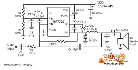
increase to the active subwoofer amplifier (TDA7294) circuit
Published:2011/5/4 9:45:00 Author:TaoXi | Keyword: increase, active subwoofer amplifier
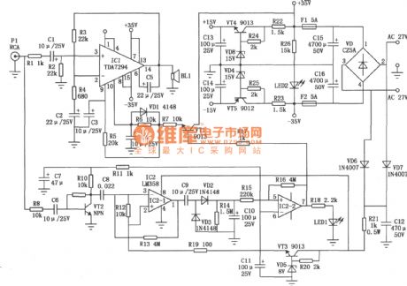
This circuit updates the audio circuit which uses the IC TDA7294. Pin-10 of the TDA7294 has the mute function, when the external power supplies the high-level voltage, the manifold is in working condition; when the external power supplies the low-level voltage, the manifold turns off, at this time the circuit power consumption is very small, pin-14 of IC1 has no output ( Standby mode). General circuits supply the high-level voltage to the pin-10 to keep it in the conduction mode, by developing this pin's functions, you can make it to meet some special requirements for work. That's why this circuit can makes the active subwoofer amplifier to have the function of standby, the circuit is reliable and responsive. (View)
View full Circuit Diagram | Comments | Reading(13006)
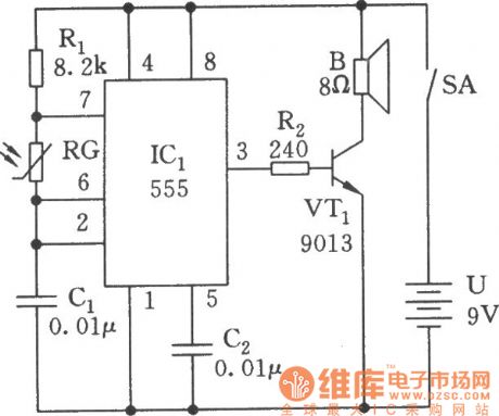
Electronic Lark Song Circuit
Published:2011/5/3 19:30:00 Author:Sue | Keyword: Electronic, Lark Song
View full Circuit Diagram | Comments | Reading(826)
uPC1321V Power Amplifier Circuit
Published:2011/5/3 8:25:00 Author:Felicity | Keyword: Power Amplifier Circuit
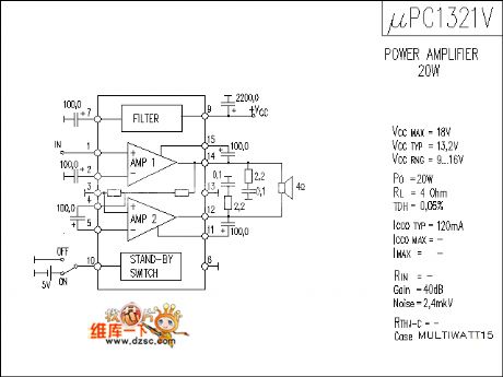
The picture above shows the uPC1321V Power Amplifier Circuit. (View)
View full Circuit Diagram | Comments | Reading(774)
| Pages:48/54 At 204142434445464748495051525354 |
Circuit Categories
power supply circuit
Amplifier Circuit
Basic Circuit
LED and Light Circuit
Sensor Circuit
Signal Processing
Electrical Equipment Circuit
Control Circuit
Remote Control Circuit
A/D-D/A Converter Circuit
Audio Circuit
Measuring and Test Circuit
Communication Circuit
Computer-Related Circuit
555 Circuit
Automotive Circuit
Repairing Circuit