
Audio Circuit
Index 42
The BA328 stereo pre-amplifier circuit
Published:2011/6/20 21:00:00 Author:Seven | Keyword: stereo, pre-amplifier
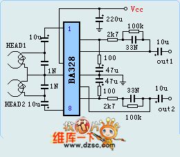
BA328 has two lines of pre-amplifier circuits, it characterizes few external elements and convenient installation,etc. It is in a single 8-pin package. The features of the circuit are as follows: the working voltage is wide, the noise is weak, open loop gain is high and left-right channel balance is good. It is often used in cassette players, car stereo radios and domestic stereo equipment. The limit parameters of BA328 are as follows: the maximum voltage of the power supply is 18v, max power consumption is 540mW, working temperature is -25-70℃.
(View)
View full Circuit Diagram | Comments | Reading(5464)
Audio power amplifier stage with LM-386 circuit
Published:2011/6/16 6:08:00 Author:John | Keyword: Audio power amplifier stage
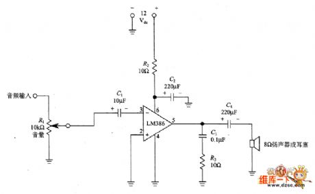
Figure shows the design based on LM-386. It is the LM-386 low-power audio level’s single-ended output configuration. This IC includes a pre-amplifier and power amplifier with the nominal output power of 250mW. LM-386 series audio power IC is simple, but high gain is needed. If it is with unreasonable configuration or if the ground is not properly configured, it may cause self-oscillation.
figure: Audio power amplifier stage with LM-386 circuit (View)
View full Circuit Diagram | Comments | Reading(1577)
The 200MHz cascode amplifier circuit principle diagram
Published:2011/6/20 21:54:00 Author:Seven | Keyword: cascode, amplifier circuit
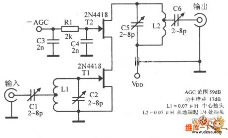
The 200MHz cascode amplifier circuit principle diagram is shown in the above figure.
AGC range:59dB; power gain:17dB;L1=0.07 μH central head; L2=0.07 μH the plug is at the 1/4 point from the earth terminal (View)
View full Circuit Diagram | Comments | Reading(1399)
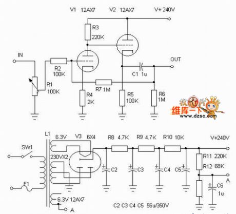
The 6U8+6900 push 421 push-pull circuit
Published:2011/6/20 22:19:00 Author:Seven | Keyword: push-pull circuit
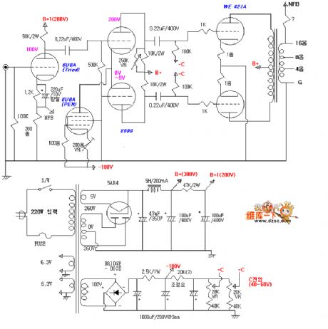
The 6U8+6900 push 421 push-pull circuit is shown as above. (View)
View full Circuit Diagram | Comments | Reading(1943)
The bota circuit
Published:2011/6/20 22:20:00 Author:Seven | Keyword: bota
The bota circuit is shown as above.
(View)
View full Circuit Diagram | Comments | Reading(947)
The stereo sound volume remote control circuit
Published:2011/6/20 11:48:00 Author:Seven | Keyword: stereo sound volume, remote control
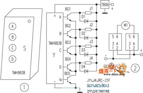
The stereo sound volume remote control circuit is shown as follows:
(View)
View full Circuit Diagram | Comments | Reading(757)
The BA532 audio power amplifier circuit
Published:2011/6/20 20:52:00 Author:Seven | Keyword: audio power amplifier
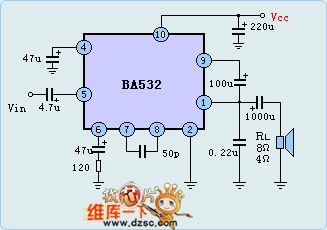
BA532 is a low-frequency power amplifier circuit which is used in OTL circuits, its output power is 5.8w, and there is the loading short, over-voltage and over-heat protection circuit, the circuit is in 10-pin package, the features of the circuit are: When the voltage of the power supply is 13.8v, the loading impedance is 8Ω, when the THD=10%, the output power may reach 5.8w, the wave rejection ratio is 40dB, the pin is the same with BA511A and BA521. The circuit is often used in vehicle stereo cassette players, radios, TV sets and cassette recorder as the power output circuit.
(View)
View full Circuit Diagram | Comments | Reading(2853)
The BTL application circuit composed of BA532
Published:2011/6/20 22:22:00 Author:Seven | Keyword: application circuit, BTL
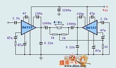
The BTL application circuit composed of BA532 is shown as above.
(View)
View full Circuit Diagram | Comments | Reading(1530)
The surrounded sound generator composed of TA8173AP
Published:2011/6/16 0:52:00 Author:Borg | Keyword: surrounded sound, generator
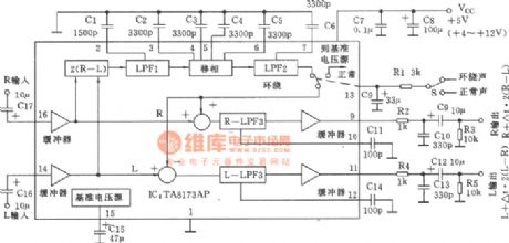
See as the figure, both the output and input are dual-channel, by the switch on 13-pin, we can choose normal sound or surrounded sound. After crossing the buffer, the input R and L signal is split into the main signal and vice signal. The vice signal is sent to the low-pass filter LPFI by R-L, then it shifts the phase, and then it crosses the low-pass filter LPF2 and is added with the main signal by the switch. The R channel signal is to do the same phase addition, so that the signal that we get is sent out by the low-pass filter LPF3 and the buffer. (View)
View full Circuit Diagram | Comments | Reading(2153)
The white noise generator
Published:2011/6/16 0:35:00 Author:Borg | Keyword: noise generator
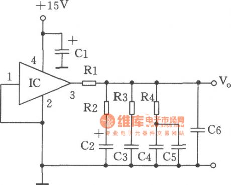
In the figure is the ICMM5837 wide-band white noise generator, the white noise is generated by the 3dB filter of the 10Hz to 40KHz octave. The noise has flat frequency distribution within 20Hz to 20kHz. The output is added on the 1Vp-p noise on the 8.5v DC LEV. This circuit is mainly used to the controllable noise source. Components selecting: integrated circuit IC: MM5837; capacitor CI:100μ25V,C2:1μ50V,C3:0.27μ63V,C4、C5:0.047/63V,C6:0.033μ63V. Resistor RI: 6.8kΩ,R2:3k,R3:1k,R4:300Ω, all of which are l/8WRJ type.
(View)
View full Circuit Diagram | Comments | Reading(1978)
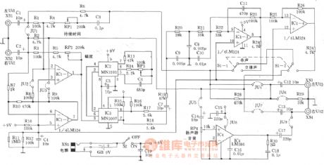
The simple mixing and surround sound generator
Published:2011/6/15 2:45:00 Author:Borg | Keyword: mixing, surround sound
View full Circuit Diagram | Comments | Reading(2401)
Close-door Reminder
Published:2011/5/12 3:06:00 Author:Sue | Keyword: Close-door Reminder
The close-door reminder can send out the sound Please close the door. when one goes in or out of the room, and the sound will stop when the door is closed. It can also be used in places like confidential room, reference room, office and so on.
Working principle:
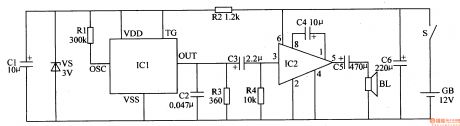
As seen in the figure 6-223, the reminder circuit is composed of power circuit, sound generator and power amplifying circuit.
The power circuit consists of battery GB, door contact switch S, current-limiting resistor R2, zener diode vs and filter capacitor C1,C6.
The sound generator consists of speech integrated circuit IC1, resistor R1,R3 and capacitor C2.
The power amplifying circuit consists of audio power amplifying integrated circuit IC2, capacitor C3-C5, resistor R4 and loudspeaker BL.
When the door is closed, S is disconnected, so the whole circuit isn't working. When the door is opened, S is connected, IC1 receives a voltage of +3V and begins to work. Its OUT terminal outputs sound signal, which will promote BL to make out the sound of Please close the door after being amplified by IC2.
When the door is closed, S is disconnected, and the whole circuit stops working.
Choices of components: R1,R2,R4:1/4W or 1/8W carbon film resistor. R2:1/2W carbon film resistor.
C1,C3-C6:aluminium electrolytic capacitor with a durable pressure of 16V. C2:monolithic ceramic capacitor or dacron capacitor.
VS:1/2W, 3V silicon voltage stabilizing diode.
IC1: Sound integrated circuit with saved signal of Please close the door. , such as HFC5203A. IC2:LM386N audio power amplifying integrated circuit.
BL: 0.5-1W, 8Ω electronic loudspeaker.
S:stroke switch. (View)
View full Circuit Diagram | Comments | Reading(1196)
Seating Position Reminder(1)
Published:2011/5/12 3:02:00 Author:Sue | Keyword: Seating Position, Reminder
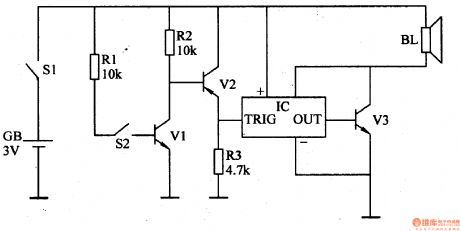
Unproper sitting position can do harm to children's eyesight and health. Now the introduced sitting position reminder can make a sound of di di or language reminding sound to remind the users of proper sitting postion.
Working Principle:
As seen in the figure 6-212, the reminder consists of electronic switch circuit GB, warning circuit and power circuit.
The electronic switch circuit consists of glass mercurial switchS2, transistor V1,V2 and resistor R1-R3.
The power circuit consists of power GB and switch S1.
When S1 is connected, GB offers the whole circuit voltage.
When the user's sitting position is proper, S2 is disconnected and the whole circuit doesn't work.
When the user's sitting position isn't proper(the distance bewteen the user and the dest is closer), S2 is connected and V1,V2 are connected. V2 generates a high voltage to IC's TRIG terminal, making IC begin to work. The OUT terminal will output audio signal which will make the di di warning sound or reminding sound of Please adjust your sitting position to avoid myopia after is is amplified by V3.
Choices of Components:
R1-R3:1/4W or 1/8W carbon film resistor.
V1,V3:S9013 or 3DGl2 silicon NPN transistor; V2: S9012 or 3CG2l silicon PNP transistor.
IC:HFC9301 exclusive integrated circuit with saved di di sound or KD56028 sound integrated circuit with saved sound of Please adjust your sitting position to avoid myopia.
S1: Miniture toggle switch; S2: KG series glass mercurial switch.
BL:8Ω、O·25W electronic loudspeaker.
GB:Two 1.5V size 5 dry batteries. (View)
View full Circuit Diagram | Comments | Reading(958)
Smoking Warning Indicator (3)
Published:2011/5/20 3:36:00 Author:Sue | Keyword: Smoking, Warning, Indicator
When the gas sensor detects no smoke, V1's breakover ability is weak because of lack of VL's infrared light. V2 then is disconnected, and IC doesn't work, BL makes no sound.
When the sensor detects smoke, the smoke will have a strong scattering effect on the infrared light sent by VL, so V1 will absorb the light and have a larger working current, which makes V2 connected and IC will begin to work. Its 7 pin will output sound signal,and BLwill makea warning sound of No Smoking! after the signal is amplified by V3. (View)
View full Circuit Diagram | Comments | Reading(643)
Smoking Warning Indicator (1)
Published:2011/5/19 2:50:00 Author:Sue | Keyword: Smoking, Warning, Indicator
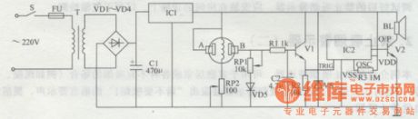
When gas sensor detects no smoke, the resistance value between A and B will be very large, and B's voltage will be low. Then V1 is disconnected, so the loudspeaker doesn't work. When gas sensor detects smoke, the resistance value between A and B will become small, making B's voltage higher, so V1 is connected. Its emitter will output high level, making IC2 begin to work, so loudspeaker BL will make a warning sound of No Smoking! When there is no smoke, the resistance value between A and B becomes large again,so V1 will stop working because of the low voltage of 1.4V.Then the warning sound stops. (View)
View full Circuit Diagram | Comments | Reading(634)
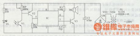
autocycle flasher principium circuit diagram
Published:2011/5/11 1:46:00 Author: | Keyword: autocycle, flasher principium
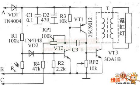
Neon light flasher assumed on autocycle back brand circuit diagram and work principle:assume a neon flashershown as the figureon autocycle back brand, which can increase safety in night,bring attention of the following vechiles, and flick when the autocycle brake.This set takes a neon tube that can justcircle the number plate,illuming it at night.VT1 and VT2 form a complementary instable multi-vibrator.BP1 and C3 decide vibrator work frequency.Signal voltage on RP2 is amplified by VT3 to drive step-up transformer T,then secondary induce high voltage to make the neon light.
elements select:expect indicated elements type,photosensitive resistant can use M45 series,requiring dark resistant>1MΩ,light resistant<10KΩ;pulse transformer T can select E12 type magnetic coreMXQ-2000,primary using 45 circle Φ0.51mm lacquered wire ,secondary using about 1500 circle Φ0.21mm high strength lacquered wire.
(View)
View full Circuit Diagram | Comments | Reading(1125)
The talk back circuit of phones
Published:2011/6/13 21:33:00 Author:Seven | Keyword: talk back
The turnratio of the step-up transformer Tis 1:25, which is coordinating with the LM380 gain of 50, then the gain of all the circuit is 1250. The resistor R0 provides with common module sound volume control. LM380 is a sound frequency integrated amplifier, which has the internal gain of 50(34dB), and the output can automatically base on the half of the power supply voltage, the input stage can engage in DC coupling or AC coupling according to the need. The output stage has short circuit current limitation and heat cutting off protection circuit. To application, the internal characters can minimize the number of the external elements. (View)
View full Circuit Diagram | Comments | Reading(836)
Buzzer circuit
Published:2011/5/19 18:28:00 Author:Christina | Keyword: Buzzer
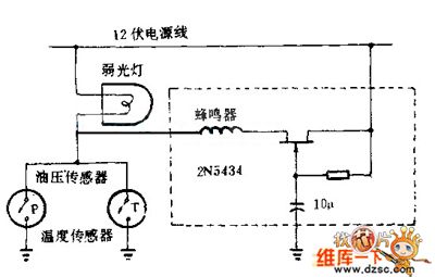
You can not judge if the engine monitoring indicator is turned on in day time, so you can use the buzzer circuit to compensate this shortage. Every time you start the engine, JFET 2N5434 will be conducted at 7 seconds delay time, so in the process of start the car and increase the hydraulic, the buzzer will not ring; at this time the indicator light monitors the oil pressure sensor and the engine temperature sensor. The whole circuit can beinstalled in the abandoned buzzer plastic shell of the bridge.
(View)
View full Circuit Diagram | Comments | Reading(883)
BA6029,BA6209N,BA6209U,BA6209V-The speed-stable circuits of TV sets
Published:2011/5/17 22:27:00 Author:Borg | Keyword: speed-stable circuits, TV sets
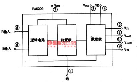
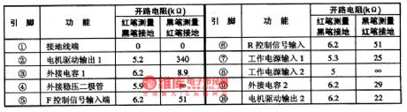
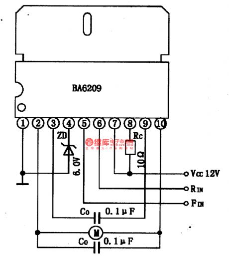
BA6029,BA6209N、BA6209U、BA6209V are speed-stable circuits of TV sets, which are produced by Toyo Corp.,Japan. It is used to drive tape motors, principle motors and tape winding motors, ordering them to stop or wind/rewind. All the internal circuits and typical application circuits of these integrated circuits are almost the same, except for the few differences in packages and parameters. The following is BA6209 as a example.1.The internal circuit and pin functions of BA6209BA6209 can drive motors directly and afford the curren of 1.5A.
(View)
View full Circuit Diagram | Comments | Reading(3203)
BA6191-the 2-channel bilateral-control integrated circuit of motor drive
Published:2011/5/17 22:29:00 Author:Borg | Keyword: 2-channel, bilateral-control
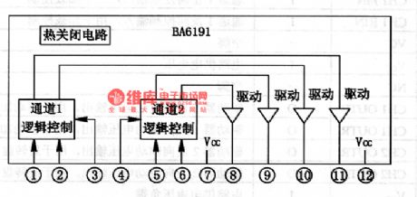
BA6191 is a 2-channel bilateral-control integrated circuit of motor drive produced by Toyo Corp., which is often used in VCD, SVCD and CVD single/multipleplayers as motor drives. 1.the internal circuit BA6191 contains logic control circuit and drive circuit, whose internal circuit is as shown in Figure 1.
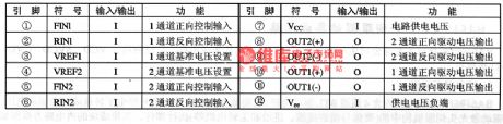
2.pin functionsBA6191 is in 12-lead single in-line package, whose pin functions and data are listed in Table 1. (View)
View full Circuit Diagram | Comments | Reading(856)
| Pages:42/54 At 204142434445464748495051525354 |
Circuit Categories
power supply circuit
Amplifier Circuit
Basic Circuit
LED and Light Circuit
Sensor Circuit
Signal Processing
Electrical Equipment Circuit
Control Circuit
Remote Control Circuit
A/D-D/A Converter Circuit
Audio Circuit
Measuring and Test Circuit
Communication Circuit
Computer-Related Circuit
555 Circuit
Automotive Circuit
Repairing Circuit