
Audio Circuit
Index 46
BA6395AFP BTL-the integrated circuit of 5-channel drive
Published:2011/5/12 20:18:00 Author:Borg | Keyword: integrated circuit, 5-channel
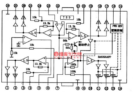
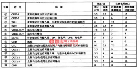
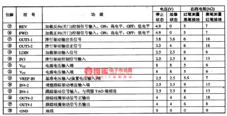
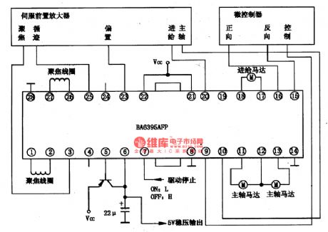
BA6395AFP is an integrated circuit of 5-channel drive produced by Rom Corp., which is used in CD and VCD players of many countries to drive focus coil, tracking coil, spindle motor, axis motor and slide motor, etc.
1.the internal circuit and pin functions of BA6395AFPBA6395AFP chips contains five drive circuits of 5-channel BTL, whose power is large. The internal circuit of the chips is shown in Figure 1. When the temperature is over 175℃, the output current will be impeded.
(View)
View full Circuit Diagram | Comments | Reading(1068)
BA6996FP-the Intergrated Circuit of the Servo drive
Published:2011/5/11 22:22:00 Author:Borg | Keyword: Intergrated Circuit, Servo-drive
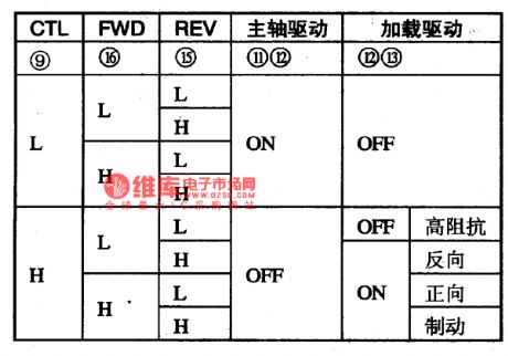
BA6996FP is a servo-driven single door intergrated circuit of laser heads produced by Rom Corp., Japan, which is used as servo-drivers in VCD, SVCD,CVD and DVD.
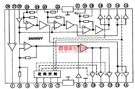
1.internal circuit
BA6996FP contains sub-circuits of 5-channel BTL and logic control, which can switches all kinds of laser head servo-driven signals into two-way driven voltage to drive all the executing components.
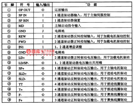
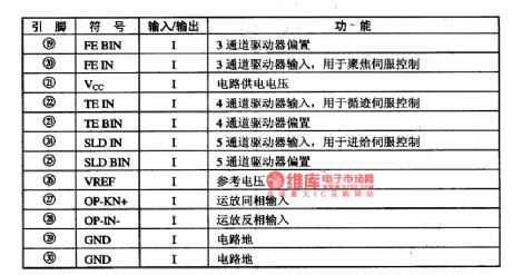
2.pin functions
BA6996FP is encapsulated in dual flat packages with 28-lead, whose pin functions and data are listed in Table 1.
(View)
View full Circuit Diagram | Comments | Reading(815)
PCMl800 digital audio decoding integrated circuit diagram
Published:2011/5/6 4:20:00 Author:Rebekka | Keyword: digital audio decoding , integrated circuit

The functions and data of audio decoder IC PCM1800 are listed in table 1. Table 1 is PCM1800 IC pin functions and data. (View)
View full Circuit Diagram | Comments | Reading(873)
Sitting Position Reminder(2)
Published:2011/5/10 0:37:00 Author:Sue | Keyword: Sitting Position, Reminder
The reminder introduced here will be put on the user's ears or hat. When the user's sitting position is not proper, it can make the warning sound of Please pay attention to your sitting position . It can be used to help office stuff and students to keep proper sitting position and avoid myopia, or to be used as doze reminder for drivers.
Working principle:
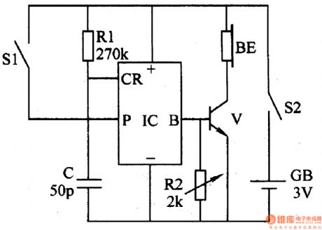
As seen in the figure 6-213, the reminder consists of mercurial switch(as leaning angle sensor)S1, resistor R1,R2, capacitor C, audio integrated circuit IC, transistor V, earphones BE, power switch S2 and battery GB.
When the sitting position is proper, S1 is disconnected and the whole circuit does't work. When user's head lean forward to a certain angle, S1 is connected and IC is triggered to work. After the output audio signal is amplified by V, BL will make a warning sound.
When we change S1's position, the angle to trigger the warning can be changed.
When we change R2's value, the tone of BE's sound can be changed.
Choices of components:
R1:1/8 metal film resistor; R2: After adjusting the tone with variable resistor, we should connect a 1/8 fixed resistor.
C:High frequency ceramic capacitor.
V:S9013 or S8050 silicon NPN transistor.
IC: Audio integrated circuit with saved signal of Please pay attention to your sitting position such as KD56028.
S1:φ3·5mm glass mercurial switch; S2: miniture toggle switch.
BE:Stereophone's inside sounder.
GB:Button cells. (View)
View full Circuit Diagram | Comments | Reading(686)
±100mA output current buffer (LF357) circuit
Published:2011/5/10 2:26:00 Author:TaoXi | Keyword: ±100mA, output current, buffer
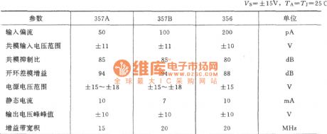
The main parameters (View)
View full Circuit Diagram | Comments | Reading(1334)
HT9246DL-An Intergrated Circuit of Pulse/Tone Dialing
Published:2011/5/10 20:16:00 Author:Borg | Keyword: Intergrated Circuit, Pulse/Tone Dialing

HT9246DL is an intergrated circuit of pulse/tone dialing which is widely used in wirless phones of multi-channels.
1.functions features
The contents of the HT9246DL intergrated circuit:pulse/tone dialing circuit, key switch signal encoding/decoding circuit, silence control circuit, hand-free control circuit, clock oscillatory circuit and other function circuit.
2.fin functions and relevent data
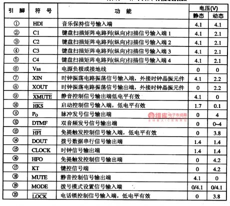
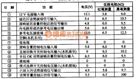
HT9246DL intergrated circuits are pinned in double-line plastic packages with 28 pinnings, whose pin functions and data are listed in Table 1-1. In the table, the pin voltage value of (19) is 4.1 when the dialing is in the pulse way, and 0V when it is in the tone way.
The static state in Table 1-1. Means off-hook, and the dynamic means that the voltage when application circuits corresponding to pinnings are working.
Table 1-1 pin functions and data of the HT9246DL circuit (View)
View full Circuit Diagram | Comments | Reading(851)
Voltage/Current Converting Circuit
Published:2011/5/9 23:46:00 Author:Sue | Keyword: Voltage/Current, Converting
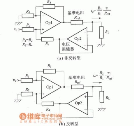
(a)Non Inverted Circuit (b)Inverted Circuit (View)
View full Circuit Diagram | Comments | Reading(677)
MC3361B Narrowband FM integrated circuit diagram
Published:2011/5/9 2:14:00 Author:Rebekka | Keyword: Narrowband FM integrated circuit
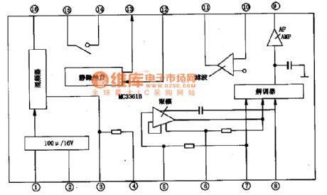
MC3361B type low-power narrowband FM integrated circuit. It is suitable for frequency duplex communication equipment, cordless telephones and remote control applications such as frequency amplifier circuit. MC3361B integrated-circuit block diagram is shown as above.
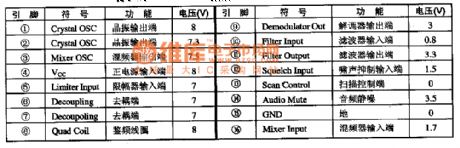
Pin functions and data.
2 MC3361B integrated circuit has two packages: One is the 16-pin dual in-line package; Another way is the surface mount work small 16-pin SMD package. The pin function and data of the IC are listed in Table.
(View)
View full Circuit Diagram | Comments | Reading(1020)
The Intergrated Circuit of BH3868BFSI2C Bus Control BBE and Audio Handling
Published:2011/5/10 10:59:00 Author:Borg | Keyword: Intergrated Circuit, Bus Control, BBE
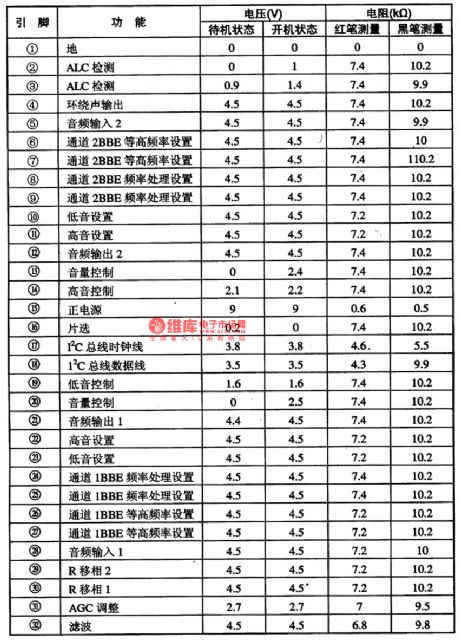
BH3868BFS is an intergrated circuit of 12C bus control BEE and audio handling which is widely used in the color TV set of Changhong CN-15 and other stereo systems, whose pin functions and data are listed in Table 1, and the data were tested in CN-15 TV sets.
Table 1 the pin functions and data of the BH3868BFS intergrated circuit (View)
View full Circuit Diagram | Comments | Reading(704)
Pocket Digital Timing Hypnotic Massager Circuit Composed of 555
Published:2011/5/9 5:09:00 Author:Sue | Keyword: Pocket, Digital Timing, Hypnotic, Massager
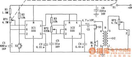
As seen in the figure is the pocket digital timing hypnotic massager circuit composed of 2 555 timers. It can satisfy people's demand on leisure and health. The circuit consists of 3 parts: timer circuit, hypnotic circuit and massager circuit. (View)
View full Circuit Diagram | Comments | Reading(885)
Time-delay Circuit with Watchdog Composed of 555
Published:2011/5/9 5:14:00 Author:Sue | Keyword: Time-delay, Watchdog

Originally this circuit was an electrified time-delay control circuit. The delayed time is decided by R1 and C1. But when watchdog circuit is added, it can be used as observation circuit for certain application systems. (View)
View full Circuit Diagram | Comments | Reading(2148)
Schmitt Trigger Used in Converting Circuit
Published:2011/5/9 5:15:00 Author:Sue | Keyword: Schmitt Trigger, Converting
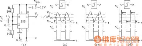
Schmitt trigger which is used in waveform transformation has extensive uses. Figure (a) shows the basic trigger circuit composed of 555. Figure (b),(c),(d) show the converting and transformation of different input signals and waveforms. (View)
View full Circuit Diagram | Comments | Reading(1172)
TTL Interface And Monostable Trigger Circuit
Published:2011/5/9 5:09:00 Author:Sue | Keyword: TTL, Interface, Monostable, Trigger

In a TTL Four-2 input and NOT gate circuit, when there is a positive pulse, after inverse triggering monostable trigger circuit composed of 555 and R1,C1, the output pulse can connect with any TTL circuit or CMOS circuit. (View)
View full Circuit Diagram | Comments | Reading(1413)
Arbitrarily Extended Charging Pulse Counter Switch Circuit
Published:2011/5/9 5:10:00 Author:Sue | Keyword: Arbitrarily Extended, Charging, Pulse, Counter, Switch
As seen in the figure, the counter switch circuit consists of a pulse control electronic switch and a time-delay circuit. (View)
View full Circuit Diagram | Comments | Reading(1219)
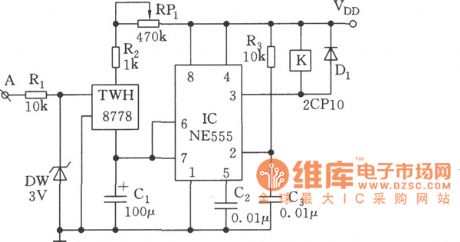
Touch Controlled Silicon Zero Passed Switch Circuit (2)
Published:2011/5/9 5:13:00 Author:Sue | Keyword: Touch, Controlled, Silicon, Zero Passed, Switch
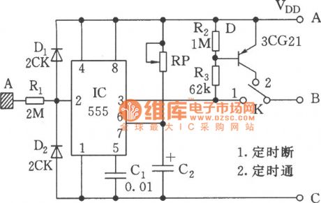
1.Timing disconnection
2.Timing connection (View)
View full Circuit Diagram | Comments | Reading(699)
Voltage Detection Circuit
Published:2011/5/9 5:17:00 Author:Sue | Keyword: Voltage, Detection
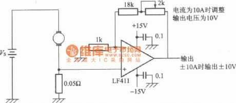
When the current is 10A, the circuit can adjust the output voltage to 10V. When output current is ±10A, the output voltage should be ±10V. (View)
View full Circuit Diagram | Comments | Reading(764)
Typical Application on M50119P Integrated Circuit
Published:2011/5/9 5:16:00 Author:Sue | Keyword: Typical Application on M50119P Integrated Circuit
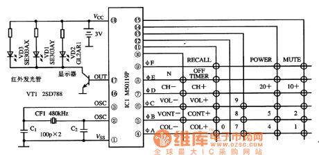
As seen in the figure is the remote controller typical application circuit composed of M50119P integrated circuit. (View)
View full Circuit Diagram | Comments | Reading(1440)
M51131L-audio and microphone sound control integrated circuit diagram
Published:2011/5/8 22:03:00 Author:Nicole | Keyword: audio, microphone, sound control
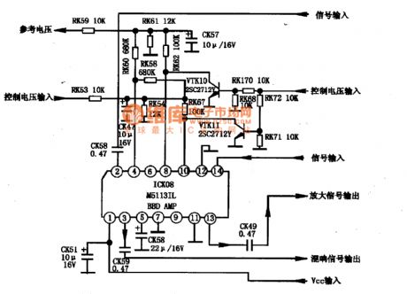
M51131L is a audio and microphone sound control integrated circuit which is produced by Mitsubishi Corp, it is mainly used in TV audio, karaoke audio system.
1. M51131L typical application circuit
The typical application circuit of M51131L integrated block is shown in the figure 1-1. This IC adopts single row 14-foot in-line package, the pin function and data of this integrated circuit is shown in the table1.
The table is the pin function and data of M51131L integrated circuit
The figure1 is the typical application circuit of M51131L integrated block
(View)
View full Circuit Diagram | Comments | Reading(2626)
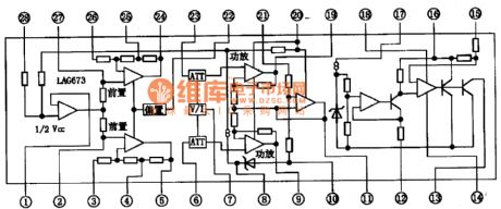
LAC673-single chip stereo paly integrated circuit diagram
Published:2011/5/9 2:42:00 Author:Nicole | Keyword: single chip, stereo, play
LAC673 is a single chip stereo paly integrated circuit which is produced by MITSVMI, it is widely used in import radio walkman.
1. LAC673 internal block and pin function
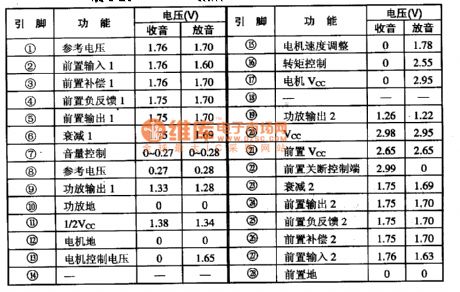
LAC673 integrated circuit contains double preamplifier, double power amplifier, DC electronic volume control circuit, DC motor steady speed circuit. The internal circuit block diagram of this integrated block is shown in the figure1. This IC adopts dual flat type package, the pin function and data of this integrated circuit is shown in the table1.
2. LAC673 typical application circuit
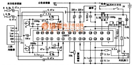
Because LAC673 integrated block is functionally complete, it can form a stereo tape player circuit with a LAC673, if adding a stereo tuner then it can form a stereo radio player circuit. The typical application circuit of LAC673 integrated block is shown in the figure1.
The figure1 is the internal circuit block diagram of LAC673 integrated block
The table1 is the pin function and data of LAC673 integrated circuit
The figure1 is the typical application circuit of LAC673 integrated block
(View)
View full Circuit Diagram | Comments | Reading(1204)
Four-channel electronic switch audio mixer circuit
Published:2011/5/6 22:01:00 Author:TaoXi | Keyword: Four-channel, electronic switch, audio mixer
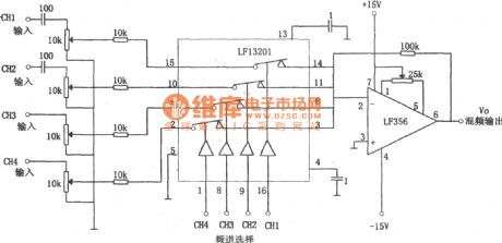
The four-channel electronic switch audio mixer circuit is as shown. The LF13201 is the four-channel analog electronic switch, the LF356 is the low-noise FET input type op amplifier. Four-channel signal is RC coupled or directly coupled by the amplifier, and is added to the electronic switch LF13201's pin-2, pin-7, pin-10 and pin-15, the single-pole double-throw switch is composed of the above pins and the pin-3, pin-6, pin-11, pin-14. The four analog switches are controlled by pin-1, pin-8, pin-9 and pin-16's external control voltage. When the control voltage has high-level voltage, the corresponding switch turns off. The control voltage is provided by the TTL and CMOS driver circuit but not the LF356 and LF13201. (View)
View full Circuit Diagram | Comments | Reading(3972)
| Pages:46/54 At 204142434445464748495051525354 |
Circuit Categories
power supply circuit
Amplifier Circuit
Basic Circuit
LED and Light Circuit
Sensor Circuit
Signal Processing
Electrical Equipment Circuit
Control Circuit
Remote Control Circuit
A/D-D/A Converter Circuit
Audio Circuit
Measuring and Test Circuit
Communication Circuit
Computer-Related Circuit
555 Circuit
Automotive Circuit
Repairing Circuit