
Audio Circuit
Index 49
FM-type Circuit of Wireless Headphones Circuit
Published:2011/5/3 5:18:00 Author:Felicity | Keyword: FM-type Circuit of Wireless Headphones Circuit,
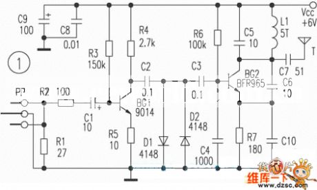
The picture above shows the FM-type Circuit of Wireless Headphones Circuit. (View)
View full Circuit Diagram | Comments | Reading(1099)
Small bed listening system circuit
Published:2011/5/3 2:46:00 Author:TaoXi | Keyword: Small, bed listening system
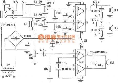
The small bed listening system circuit is as shown. This system uses two TDA2822M and has the features of small, simple and good sound, particularly enhanced the bass, so it is very suitable for the fans who live in the dormitory.
IC1, IC2 are the stereo power amplifier integrated circuit TDA2822M, the two-channel power amplifier circuit is composed of IC1, the audio signal gets into the ICl through the resistance R1, R3 and double potentiometer RP1-1, RPl-2, the amplified audio signal promotes the speaker BL1, BL2 to work. IC2 (BTL circuit) constitutes the bass amplifier, switch Sl controls it. Because the BTL circuit power dissipation is high, you need to add the heatsink on IC2. In addition, because there is no low-pass filter installed on the bass amplifier, so in use, you need to use the audio tone control circuit machine or use the small bass speaker to enhance the bass. (View)
View full Circuit Diagram | Comments | Reading(4358)
Principle Circuit of Stereo Driver
Published:2011/5/3 2:33:00 Author:Felicity | Keyword: Principle Circuit of Stereo Driver ,
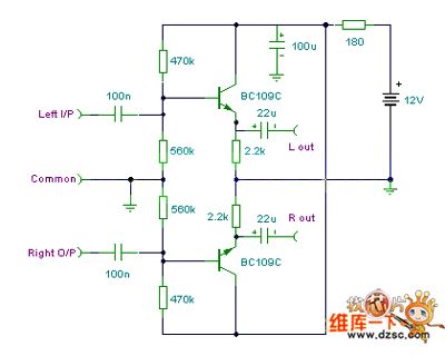
Principle Circuit of Stereo Drivor is showed in the picture above. (View)
View full Circuit Diagram | Comments | Reading(838)
Generator Circuit
Published:2011/5/3 2:25:00 Author:Felicity | Keyword: Generator Circuit,
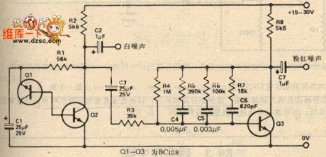
Generator Circuit is showed in the picture above. (View)
View full Circuit Diagram | Comments | Reading(714)
SRS effect processor circuit
Published:2011/4/28 0:51:00 Author:TaoXi | Keyword: SRS, effect processor
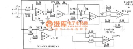
The SRS effect processor circuit's left and right channels output the L, R, n(L+R), ±f(L-R) mixed-signal. L+R means intermediate information, n means mixing ratio ( contrast adjustment); L-R means surround information, let it goes through the 300Hz ~ 10kHz filter, you can get the f(L-R), if you change the filter, you also change the sense of space . The circuit running stereo and Dolby surround software can eliminates the sense of level , and you can feel the surround sound that you never felt.
(View)
View full Circuit Diagram | Comments | Reading(5211)
music-type fridge door-close reminding circuit composed of CIC2851E
Published:2011/4/26 21:47:00 Author:TaoXi | Keyword: music-type, fridge door-close reminding
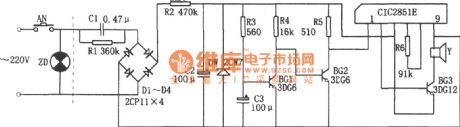
The music-type fridge door-close reminding circuit is as shown. This circuit is composed of the rectifier voltage regulator circuit, delay circuit, music IC CIC2851E and the speaker.etc. The reduce-rectify voltage circuit supplies the 3V power to the whole circuit.
When you open the refrigerator door, switch AN turn on, capacitor C3 charged by the R3 and the base potential of the BG1 increase, after 20 minutes, voltage of C3 makes the BG1 turned on, so BG2 turns off, CIC2851E starts working, the output music signal is amplified by BG3 to drive the speaker Y send out the music of christmas. If the fridge door does not close, the music will not stop. The length of delay time can be selected by master, generally between 5 to 15 seconds. This circuit takes 20 seconds.
The circuit requires the voltage between two ends of DW is about 3V, if the voltage is too high, it is easy to damage the integrated circuits. Resistor R6 is used to adjust the speed of music rhythm, the range of R6 is 20kΩ ≤ R6 ≤ 120kΩ. (View)
View full Circuit Diagram | Comments | Reading(737)
135 film positioner (C180、TWH8751) circuit
Published:2011/4/26 21:44:00 Author:TaoXi | Keyword: film positioner
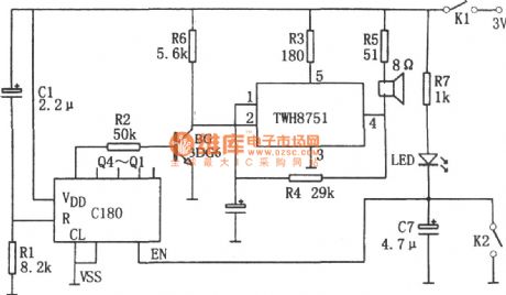
The 135 film positioner (C180、TWH8751) circuit is as shown. This circuit is composed of the counter C180 and TWH8751. And the TWH8751 forms the oscillator with 1kHz oscillation frequency.
The count switch K2 composed of the a wire and the device body at the position of 135 film's holes, when the 135 film moves, each time the contact plate contacts the body, this circuit produces a count signal. When you open this device, the contact plate of first hole contacts the body, C180 has been reset. When the nineth hole of the photo comes, there will be 8 count signal, so the Q4 of C180 has high-level voltage to turn on the BG, pin-4 outputs the signal to drive the speaker to tell master the photo is in position.
When the circuit is debugging, you should close the switch K2 first, then close the power switch K1 to make the LED light, Q1~Q4 have low-level voltage. Then turn on and off the K2 eight times, Q4 has high-level voltage. (View)
View full Circuit Diagram | Comments | Reading(1134)
Using TDA7052 as single-chip radio circuit diagram
Published:2011/4/27 3:46:00 Author:Rebekka | Keyword: single-chip radio circuit
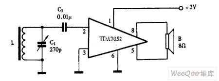
Using TDA7052 as single-chip radio circuit diagram is shown as above. (View)
View full Circuit Diagram | Comments | Reading(4596)
Using TA7641 as wired interphone circuit diagram
Published:2011/4/27 3:43:00 Author:Rebekka | Keyword: wired interphone
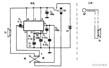
Using TA7641 as wired interphone circuit diagram is shown as above. (View)
View full Circuit Diagram | Comments | Reading(1373)
Using LM386 as multi-purpose radio circuit diagram
Published:2011/4/27 3:32:00 Author:Rebekka | Keyword: multi-purpose radio

Using LM386 as multi-purpose radio circuit diagram is shown as above. (View)
View full Circuit Diagram | Comments | Reading(4248)
Using KD-28 as single-chip radio circuit diagram
Published:2011/4/27 3:29:00 Author:Rebekka | Keyword: single-chip radio
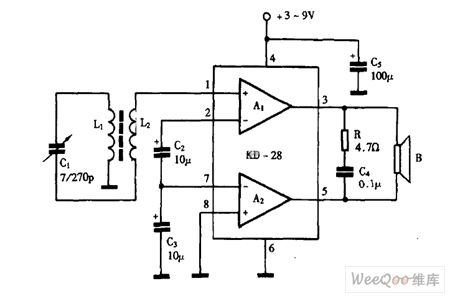
Using KD-28 as single-chip radio circuit diagram is shown as above. (View)
View full Circuit Diagram | Comments | Reading(1295)
Using LM386 as single-chip radio circuit diagram
Published:2011/4/27 3:28:00 Author:Rebekka | Keyword: single-chip radio
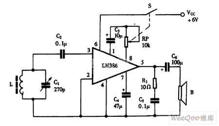
Using LM386 as single-chip radio circuit diagram is shown as above. (View)
View full Circuit Diagram | Comments | Reading(8043)
Using CXA1191 German Desheng radio circuit diagram
Published:2011/4/27 3:07:00 Author:Rebekka | Keyword: German Desheng, radio circuit
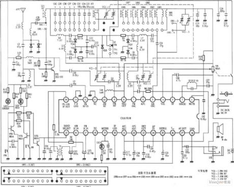
Using CXA1191 German Desheng radio circuit diagram is shown as above. (View)
View full Circuit Diagram | Comments | Reading(8326)
FM wireless headset circuit diagram
Published:2011/4/27 3:03:00 Author:Rebekka | Keyword: FM wireless headset
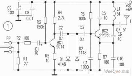
FM wireless headset circuit diagram is shown as above. (View)
View full Circuit Diagram | Comments | Reading(1245)
McIntosh C22 electron tube preamp circuit diagram
Published:2011/4/20 9:09:00 Author:Nicole | Keyword: McIntosh, electron tube, C22
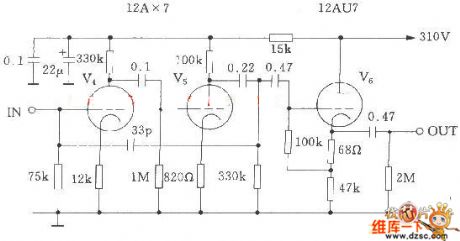
View full Circuit Diagram | Comments | Reading(5628)
Light emission and audio probe circuit
Published:2011/4/14 4:36:00 Author:Nicole | Keyword: light emission, audio probe
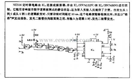
NE556 timer circuit is connected into oscillator by IC3, and controlled by IC1(SN74132N) and IC2(SN7486N). It can use audio vibration with digital logic point static state, it is convenient for blind experimental personnel. When it happens a logic abrupt change form 1 to 0 or 0 to 1, once the duration is beyond 50ns, this circuit can detect, and send out a report with dodo . LED is usedfor naked-eye observatio, when the input is logic 1, then LED light emits. (View)
View full Circuit Diagram | Comments | Reading(1004)
Bus stop indicator (CD4516、CD4514、555、KD9300) circuit
Published:2011/4/26 3:20:00 Author:TaoXi | Keyword: Bus stop, indicator

The bus stop indicator (CD4516、CD4514、555、KD9300) circuit is as shown. This circuit is composed of the 555 monostable delay circuit, counter IC2, decode monitor IC3 and the audio delay circuit.etc.
The monostable delay circuit is composed of the 555 and Rt, Ct, the delay time is td1=1.1RtCt. Counter IC2 can be preset the 4-bit reversible counter CD4516. IC3 is the 4-bit latch 4-16 line decoder. The audio circuit is composed of the music integrated circuit IC4 (KD9300) and the speaker.etc.
If you press the switch AN, IC1 outputs the delay pulse to counter IC2, IC2 pluses 1 (minuses 1) count, the output Q1~Q4 get into the IC3 to be decoded, then feedback to the IC3 by the IC5.
Each time the car go into a station, the driver press the AN to help the passengers to get off easily. (View)
View full Circuit Diagram | Comments | Reading(3064)
The TDA1521 subwoofer circuit and the speaker drawing circuit
Published:2011/4/26 7:11:00 Author:TaoXi | Keyword: subwoofer, speaker drawing

The TDA1521 subwoofer circuit and the speaker drawing circuit is as shown. (View)
View full Circuit Diagram | Comments | Reading(1938)
Multi-function digital radio circuit
Published:2011/4/26 8:06:00 Author:TaoXi | Keyword: Multi-function, digital radio

Circuit Principle
The AM-FM switch is one kind of FM AM conversion circuit that is composed of the Q2, Q3, R5-R8 and c7, power switch SW3 turns on, Q2 conducts and 03 cuts off, the A/F port outputs the high-level voltage, the voltage from R107 to the pin-15 of u1, so pin-15 of u1 has the high-level voltage and automatically switch to FM band.
The FM high frequency signal which is received by the rod antenna is also amplified by the c101 to the Q101, and then pass the bandpass filter (compose of c104, L101, c105, c106) to pin-12 of u1, and then the FM signal of pin-12 is amplified by the selected frequency amplifier and the frequency selection circuit (compose of PVC, C109, L103). The oscillator circuit is composed of PVC, c110, L104, the LO signal inputs from pin-7 and outputs from pin-14.
The audio signal of u1's pin-23 is coupled by the c123 and outputs from pin-24. w1 is the electronic volume control potentiometer, it controls the level of u1's pin-4 to control the volume. The output audio signal of u1's pin-23 send to the internal power amplifier of u1's pin-24, then the amplified audio signal from pin-27 drives the speaker or headphone. (View)
View full Circuit Diagram | Comments | Reading(2299)
555 multi-purpose car alarm circuit
Published:2011/4/26 8:17:00 Author:TaoXi | Keyword: multi-purpose, car alarm circuit
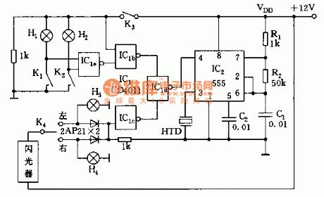
As the figure shown, alarm circuit is composed of a 555 and a four 2-input NAND gate circuit. When the oil pressure is too low and the brake pressure is too low, this circuit will issue the warning sound; When the car is steering, this circuit will issue the intermittent sound to tell the driver turn off the turn-light. (View)
View full Circuit Diagram | Comments | Reading(1166)
| Pages:49/54 At 204142434445464748495051525354 |
Circuit Categories
power supply circuit
Amplifier Circuit
Basic Circuit
LED and Light Circuit
Sensor Circuit
Signal Processing
Electrical Equipment Circuit
Control Circuit
Remote Control Circuit
A/D-D/A Converter Circuit
Audio Circuit
Measuring and Test Circuit
Communication Circuit
Computer-Related Circuit
555 Circuit
Automotive Circuit
Repairing Circuit