
Audio Circuit
Index 40
KA2211 audio IC circuit
Published:2011/6/30 19:24:00 Author:TaoXi | Keyword: audio, IC
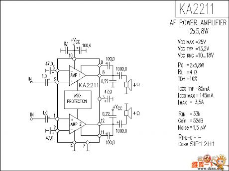
The KA2211 audio IC circuit is as shown in the figure:
(View)
View full Circuit Diagram | Comments | Reading(827)
KA2213 audio IC circuit
Published:2011/6/30 19:26:00 Author:TaoXi | Keyword: audio, IC
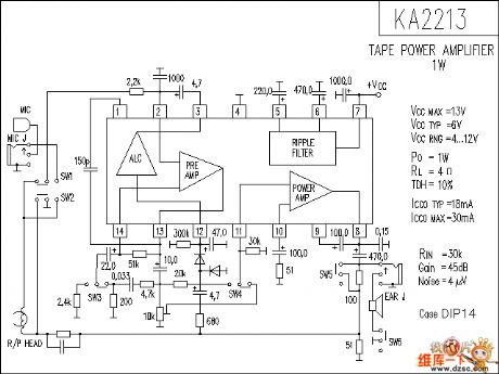
The KA2213 audio IC circuit is as shown in thefigure:
(View)
View full Circuit Diagram | Comments | Reading(1218)
KA2214 audio IC circuit
Published:2011/6/30 19:27:00 Author:TaoXi | Keyword: audio, IC
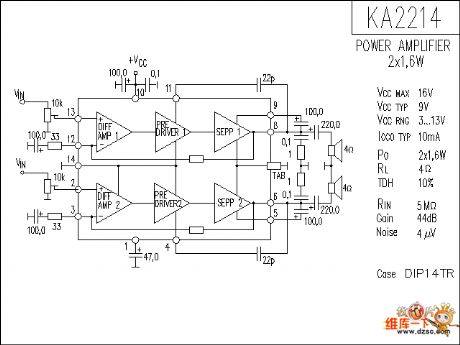
The KA2214 audio IC circuit is as shown in the figure:
(View)
View full Circuit Diagram | Comments | Reading(858)
KA22135 audio IC circuit
Published:2011/6/30 19:27:00 Author:TaoXi | Keyword: audio, IC
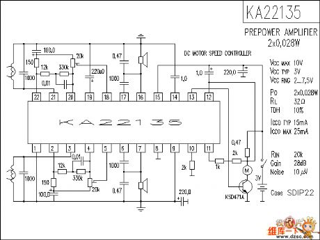
The KA22135 audio IC circuit is as shown in the figure:
(View)
View full Circuit Diagram | Comments | Reading(859)
LA1185 audio IC circuit
Published:2011/6/30 19:28:00 Author:TaoXi | Keyword: audio, IC
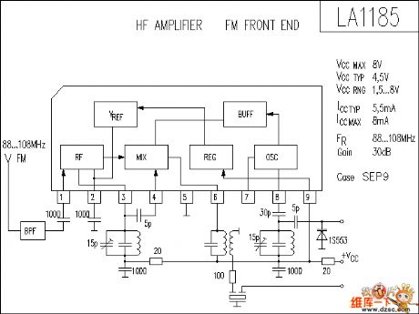
The LA1185 audio IC circuit is as shown in the figure:
(View)
View full Circuit Diagram | Comments | Reading(3620)
LA1186N audio IC circuit
Published:2011/6/30 19:29:00 Author:TaoXi | Keyword: audio, IC
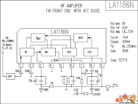
The LA1186N audio IC circuit is as shown in the figure:
(View)
View full Circuit Diagram | Comments | Reading(2491)
LA1260 audio IC circuit
Published:2011/6/30 19:30:00 Author:TaoXi | Keyword: audio, IC
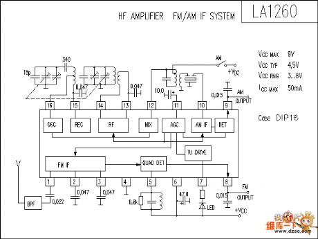
The LA1260 audio IC circuit is as shown in the figure:
(View)
View full Circuit Diagram | Comments | Reading(5869)
LA1265 audio IC circuit
Published:2011/6/30 19:31:00 Author:TaoXi | Keyword: audio, IC
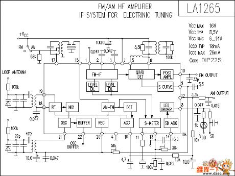
The LA1265 audio IC circuit is as shown in the figure:
(View)
View full Circuit Diagram | Comments | Reading(4841)
The touched stereo circuit
Published:2011/6/29 6:37:00 Author:Seven | Keyword: touched stereo
The touched stereo circuit is shown as above.
(View)
View full Circuit Diagram | Comments | Reading(1013)
The low-noise, high-efficiency PWM step-down converting power supply composed of MAX887H
Published:2011/6/15 6:59:00 Author:Borg | Keyword: low-noise, high-efficiency, step-down
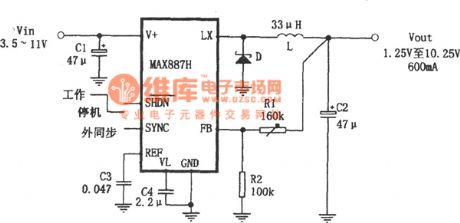
In the figure is an adjustable step-down power supply which is based on the low-noise, high-efficiency PWM and it has a few external elements. The features of the circuit are: (1) the input voltage is 3.5v~11.5v, the output voltage is 1.25v~10.25v; (2) the output current is 600mA, and the static current is 200μA. And when it is standby, the current is only 2.5μA; (3) the switching efficiency is 95%; (4) the stable working frequency of MAX887 is 300kHz, which effectively reduces the sizes and costs of the external elements. The whole circuit can be very small, which is suitable for micro-equipment. (View)
View full Circuit Diagram | Comments | Reading(805)
LM3886 production amplifier circuit
Published:2011/6/19 4:00:00 Author:John | Keyword: amplifier
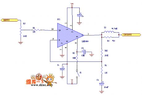
LM3886 is used to make amplifier. LM3886 is a National Semiconductor’s high-fidelity power amplifier IC with over-voltage protection and over-temperature protection. Its external circuit is simple and easy to make. Its performance is as follows: VCC = ± 28V OUTPUT = 68W/4Ω, 38W/8Ω VCC = ± 35V OUTPUT = 50W/8Ω peak power: 135W SNR ≥ 92db conversion rate: 19V/us intermodulation distortion: 0.04% 11-lead TO -220 mute function SPiKeTM protection LM3886 comes in two models: LM3886TF and LM3886T. The former one is with insulated heat sink and the latter one is not insulated. (View)
View full Circuit Diagram | Comments | Reading(2594)
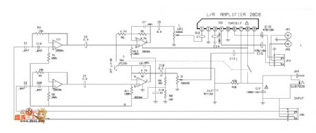
LM1036 + TDA1521 simplest high-quality power amplifier circuit
Published:2011/6/21 0:11:00 Author:John | Keyword: amplifier

LM1036 + TDA1521 simplest high-quality power amplifier circuit is shown.
(View)
View full Circuit Diagram | Comments | Reading(8242)
TDA1517 amplifier circuit
Published:2011/6/21 0:10:00 Author:John | Keyword: amplifier
TDA1517 amplifier circuit is shown.
(View)
View full Circuit Diagram | Comments | Reading(7720)
TDA2030A amplifier circuit
Published:2011/6/21 0:11:00 Author:John | Keyword: amplifier
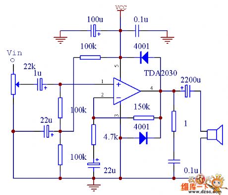
TDA2030A amplifier circuit is shown.
(View)
View full Circuit Diagram | Comments | Reading(8355)
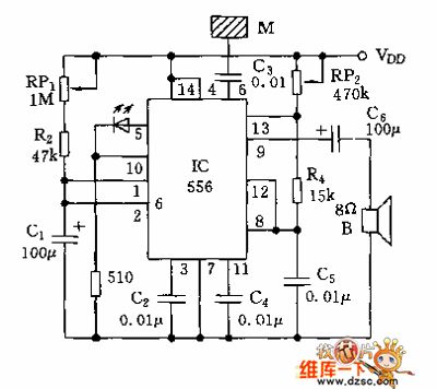
Oscillation and impact acousto-optic alarm circuit diagram
Published:2011/6/23 21:25:00 Author:Nicole | Keyword: Oscillation, impact, acousto-optic alarm
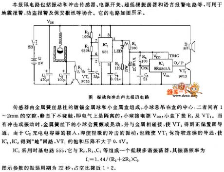
The sensor is composed of tinned gold ball which is hung on gold spring wire and small gold box, the ball is hung on the center of the box, it has 1~2mm gap, it can not be touched in the condition of state, namely, the electricity is isolated, the ball is connected to power supply VDD, the box is connected to R1 and VT1. When it has impact or oscillation, the ball will thrill or shake, and it is connected to the gold, VT1 obtains positive bias and turns on. Due to C2 charging capacitor is connected, even slight impact or oscillation, VT1 also can keep constant turn-on, then IC1, IC2 will obtain ground loop, VT1's saturated voltage drop is not higher than 0.4V.
IC1 adopts time base circuit 555, the low frequency multivibrator is made of IC1 and R2, R3, R4, the oscillation frequency is fc=1.44/(R2+2R3)C3.
(View)
View full Circuit Diagram | Comments | Reading(1791)
The audio signal generator of HFC5203A
Published:2011/6/26 5:31:00 Author:Borg | Keyword: audio signal, generator

In the figure is the audio signal generator, which can be used to detect radios, loudspeakers and other repairing instruments, and it characterizes little size, light weight, low power, simple structure, easy carry, and it's different from other signal generators that can only launch single frequency, it can output the continuous and repeated audio signals that are stored in the circuit storage. (View)
View full Circuit Diagram | Comments | Reading(917)
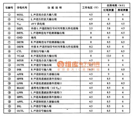
BA38805 audio phase and harmonic distortion correction integrated circuit
Published:2011/6/22 7:27:00 Author:Christina | Keyword: audio phase, harmonic distortion, correction, integrated circuit
The BA3880S is one kind of audio phase and harmonic distortion correction integrated circuit that is produced by the ROHM company. It can be used in wide range of applications such as the domestic and imported sound systems, the TV sound systems and the computer audio systems.
1.Features
The BA38805 can compensate the distortion which is caused by the power amplifier and speaker characteristics to reproduce the original audio signal.
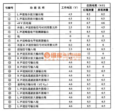
2.Pin functions and data
The BA38805 is composed of the left and right sound channels mixed amplifier, the left and right sound channels voltage control amplifier, the left and right sound channels peak level detector, the the left and right sound channels high-pass and low-pass filter, and the reference voltage circuit.
Table 1 The pin functions and data of the BA38805
(View)
View full Circuit Diagram | Comments | Reading(1006)
BA3880AS audio processing integrated circuit
Published:2011/6/22 8:40:00 Author:Christina | Keyword: audio processing, integrated circuit
The BA3880AS is designed as one kind of audio processing integrated circuit that is produced by the Toyo company, and it can be used in the TV audio, the home audio, the multimedia audio and the car audio systems.
1.Features
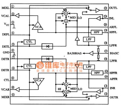
The BA3880AS has two channels of audio signal processing circuits with the same function, the audio signal processing circuit has the functions of the left and right sound channels stereo signal mix, and the sound processing. Every channel of audio signal processing circuit is composed of the reversed phase amplifier circuit, the high-pass and low-pass filter circuit, the mixed amplifier circuit, the peak level detection circuit and other accessibility circuit. The block diagram of the internal circuit is as shown in figure 1.
Figure 1 The internal circuit block diagram of the BA3880AS
2.Pin functions and data
The BA3880AS uses the 22-pin dual-row DIP package, the pin functions and dataare as shown in table 1.
Table 1 The pin functions and data of the BA3880AS
(View)
View full Circuit Diagram | Comments | Reading(973)
The self-made AC auto regulator circuit
Published:2011/6/25 1:54:00 Author:qqtang | Keyword: self-made, auto regulator
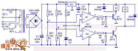
Circuit principle: the circuit principle of the regulator is shown in the figure. It consists of sub-circuits of power supply, Vref, voltage sampling comparing and so on. The mains is input from 1-head and 2-head of the transformer, the 3-head and 4-head are the self-coupling regulating heads, the 5-head and 6-head are the power supply of the control circuit and sampling head. When the mains voltage is normal, as the voltage on point C is 3V all the time(i.e it is got from the step-down of R1 and the regulation of DW), both the voltages on A and B are higher than 3V, so both A1 and A2 output low LEV; when the mains power is down, the voltages on 5-head and 6-head are also falling down.
(View)
View full Circuit Diagram | Comments | Reading(941)
The 100~200W full-automated regulator profile circuit of the dual relays
Published:2011/6/25 20:56:00 Author:qqtang | Keyword: full-automated regulator, profile circuit
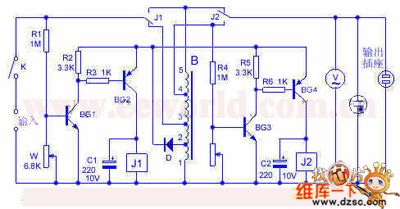
Circuit principles: the grid power supply is connected with the 3-pin of transformer B by the switch and the normally closed spot J. R1 is the sampling resistor, BG1 and BG2 compose the control circuit, which changes the control spot by adjusting W. When the grid voltage is lower than 220V, the normally closed spot makes transformer B form a step-up style. When the output voltage is not higher than 220V, J gets through the 5-pin of the transformer. If the voltage is higher than 220v, J2 is pulling in and connected with the 4-pin of the transformer. When the grid voltage is over 220V, R1 is sampling, which pushes J1 to pull in and connect with 5-pin of the transformer, and the step-down style is formed.
(View)
View full Circuit Diagram | Comments | Reading(982)
| Pages:40/54 At 202122232425262728293031323334353637383940Under 20 |
Circuit Categories
power supply circuit
Amplifier Circuit
Basic Circuit
LED and Light Circuit
Sensor Circuit
Signal Processing
Electrical Equipment Circuit
Control Circuit
Remote Control Circuit
A/D-D/A Converter Circuit
Audio Circuit
Measuring and Test Circuit
Communication Circuit
Computer-Related Circuit
555 Circuit
Automotive Circuit
Repairing Circuit