
Audio Circuit
Index 34
TEANA A33-EL Reversing Light Circuit
Published:2011/7/14 8:40:00 Author:Joyce | Keyword: TEANA, Reversing Light
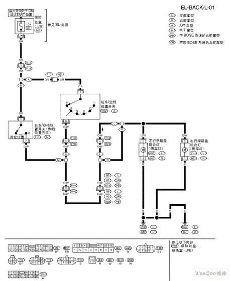
TEANA A33-EL Reversing Light Circuit (View)
View full Circuit Diagram | Comments | Reading(756)
TEANA A33-EL Stoplight Circuit One
Published:2011/7/14 8:40:00 Author:Joyce | Keyword: TEANA , Stoplight
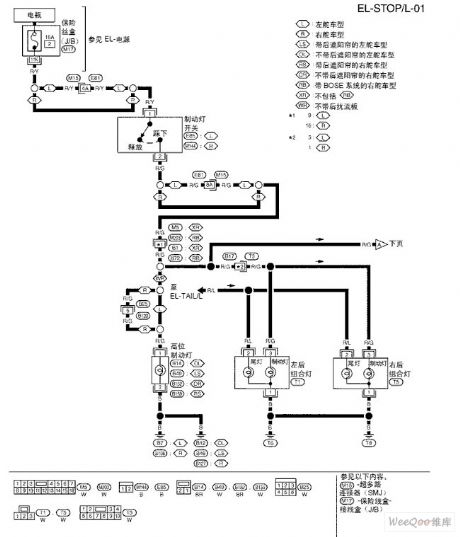
TEANA A33-EL Stoplight Circuit One (View)
View full Circuit Diagram | Comments | Reading(696)
TEANA A33-EL Headlamp(Xenon) Circuit One
Published:2011/7/14 8:41:00 Author:Joyce | Keyword: TEANA , Headlamp
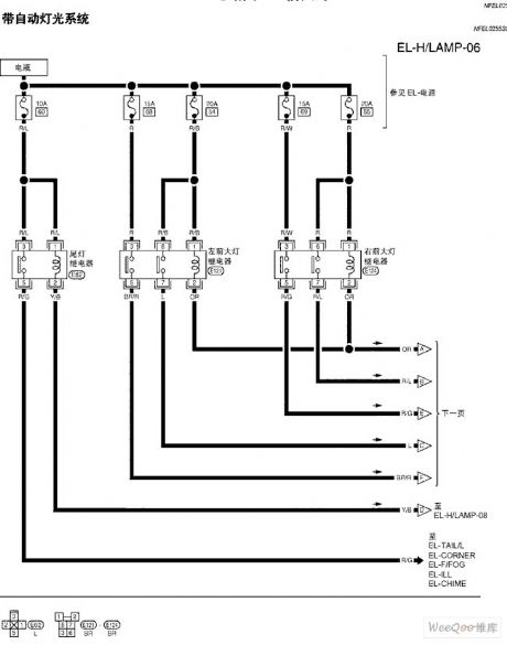
TEANA A33-EL Headlamp(Xenon) Circuit (View)
View full Circuit Diagram | Comments | Reading(698)
TEANA A33-EL Headlamp(Xenon) Circuit Two
Published:2011/7/14 8:41:00 Author:Joyce | Keyword: TEANA , Headlamp
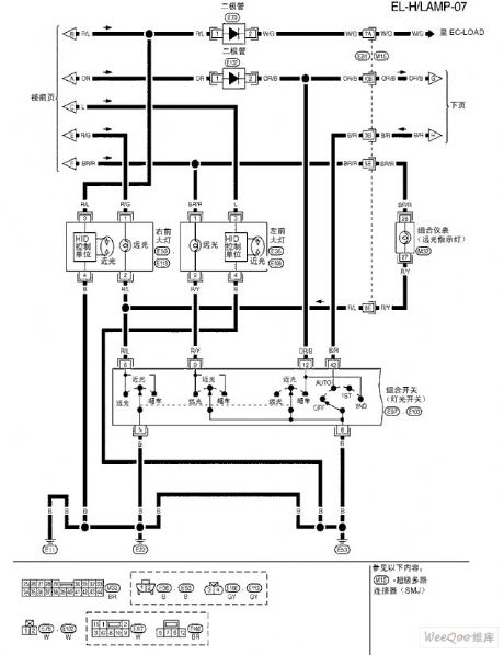
TEANA A33-EL Headlamp(Xenon) Circuit (View)
View full Circuit Diagram | Comments | Reading(693)
TEANA A33-EL Headlamp(Xenon) Circuit Three
Published:2011/7/14 8:41:00 Author:Joyce | Keyword: TEANA , Headlamp
TEANA A33-EL Headlamp(Xenon) Circuit (View)
View full Circuit Diagram | Comments | Reading(710)
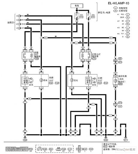
TEANA A33-EL Headlamp(Xenon) Circuit Four
Published:2011/7/14 8:42:00 Author:Joyce | Keyword: TEANA , Headlamp
TEANA A33-EL Headlamp(Xenon) Circuit (View)
View full Circuit Diagram | Comments | Reading(585)
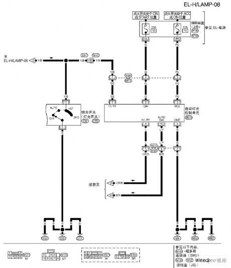
TEANA A33-EL Headlamp(Xenon) Circuit Five
Published:2011/7/14 8:42:00 Author:Joyce | Keyword: TEANA, Headlamp
TEANA A33-EL Headlamp(Xenon) Circuit (View)
View full Circuit Diagram | Comments | Reading(737)
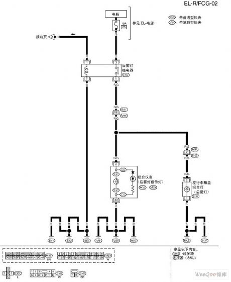
TEANA A33-EL Front Foglight Circuit
Published:2011/7/14 8:39:00 Author:Joyce | Keyword: TEANA , Front Foglight
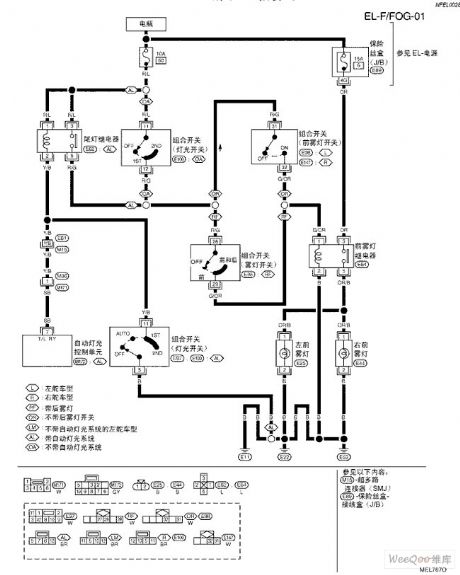
TEANA A33-EL Front Foglight Circuit (View)
View full Circuit Diagram | Comments | Reading(615)
TEANA A33-EL Rear Foglight Circuit One
Published:2011/7/14 8:40:00 Author:Joyce | Keyword: TEANA , Rear Foglight
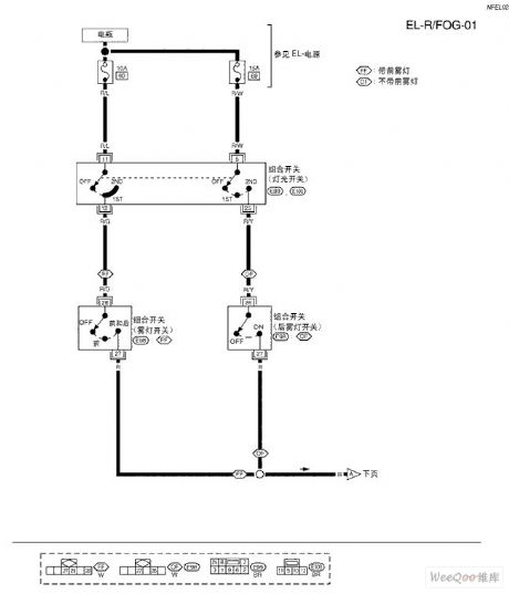
TEANA A33-EL Rear Foglight Circuit (View)
View full Circuit Diagram | Comments | Reading(627)
TEANA A33-EL Rear Foglight Circuit Two
Published:2011/7/14 8:39:00 Author:Joyce | Keyword: TEANA , Rear Foglight
TEANA A33-EL Rear Foglight Circuit (View)
View full Circuit Diagram | Comments | Reading(695)
Visitor or Family Member Differentiated Doorbell Circuit
Published:2011/7/14 0:35:00 Author:Joyce | Keyword: Visitor , Family Member , Differentiated Doorbell
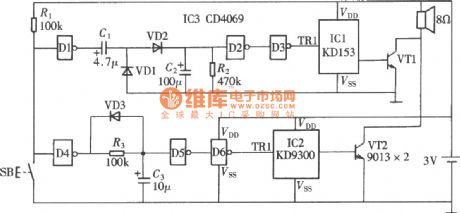
As shown in the figure is a visitor or family member differentiated doorbell(CD4069、KD9300) circuit, which can tell whether it is a visitor or a family member by hearing the times of the doorbell rings. (View)
View full Circuit Diagram | Comments | Reading(873)
Sprinkler Sound Effects Artificial Circuit
Published:2011/7/14 0:36:00 Author:Joyce | Keyword: Sprinkler , Sound Effects , Artificial
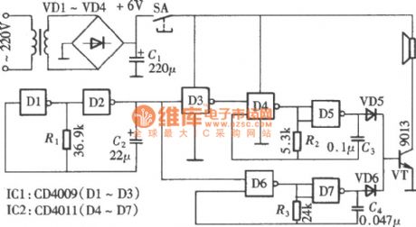
Sprinkler sound effects artificial circuitis composedof a CD4069 and a CD4011, which form three groups of multivibrator with different frequencies. After mixing and modulating, it will produce a sound simulating that of water sprayer. The circuit is as shown in the figure. Two gates of CD4069 in the circuit D1, D2 compose a low frequency multivibrator with R1 and C2, whose function is to control the two audio oscillators to work by turns through cyclical change of the output pulse. (View)
View full Circuit Diagram | Comments | Reading(886)
Increasing-volume Close-the-door Reminder Circuit
Published:2011/7/14 0:34:00 Author:Joyce | Keyword: Increasing-volume Close-the-door, Reminder
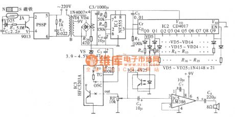
As shown in the figure is an increasing-volume close-the-door reminder circuit. It is used in confidential rooms of banks or other organizations to remind people to shut the door when in and out. When the door remains unclosed for 10s after it is opened, it will give a reminder every two seconds Please close the door with increasing-volume of sound, it will not stop until it is closed. (View)
View full Circuit Diagram | Comments | Reading(889)
9W Audio Power Amplifying Circuit of μPC2002
Published:2011/7/13 8:22:00 Author:Michel | Keyword: 9W Audio Power, Amplifying Circuit
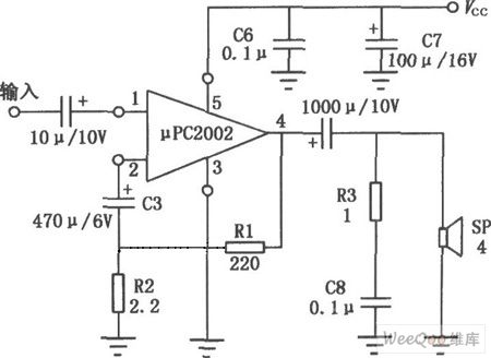
μPC2002 is audio power amplifying IC and it uses 5 feets single in-line plastic package and its pin's shape is divided into H and V type.This circuit output power is large and its distoration is small,the noise is low and the impulsive sound is low when it starts up. It also has surge-protector of the power supply,over-voltage and short-circuit overload protection. Thus it's widely used in car stereos, audio power amplifier of recorders.And its typical application circuit is shown as above. (View)
View full Circuit Diagram | Comments | Reading(1441)
Telephone audio amplification and recording device
Published:2011/6/30 21:51:00 Author:zj | Keyword: Telephone, audio amplification, recording

View full Circuit Diagram | Comments | Reading(749)
Telephone automatic recording control circuit
Published:2011/7/15 3:15:00 Author:Fiona | Keyword: automatic recording control
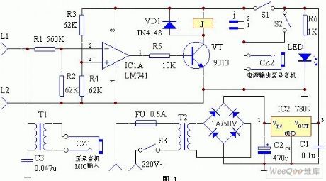
Voltage comparator which is compose of integrated circuit IC1 ( LM741) and external components is used for monitoring the telephone line voltage between L1 and L2. When the ordinary dial-up telephone is in hook state,the voltage between L1 and L2 is about 60V;when having a ringing current,it adds communication signal about 100V;when picking up the telephone receiver,the voltage between L1 and L2 drops to about 10V. Using this voltage change can judge out the telephone working state.Every time when picking up the telephone receiver,the control circuit automatically charges the recorder,then the recorder begins recording;when hanging up the telephone,the recorder automatically turns off the power to stop the recording.
(View)
View full Circuit Diagram | Comments | Reading(940)
Program Controlled Gain Amplifier Circuit
Published:2011/7/18 6:27:00 Author:Sue | Keyword: Program Controlled, Gain Amplifier
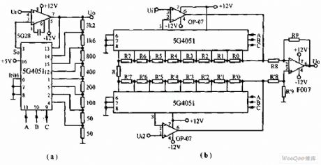
The circuit is differential input program controlled gain amplifier circuit. 5G4051 works as a single-pole eight-throw switch. When its pin 6 has low level, it is corresponding to one state of A,B,C. When we connect the channel and change one state, the feedback resistance value will be changed once and the corresponding voltage gain will be changed once. The states of the two 5G4051 are changing simultaneously and the output voltage will be differential amplified by F007. (View)
View full Circuit Diagram | Comments | Reading(980)
High-precision Linear Amplifier Circuit
Published:2011/7/18 1:26:00 Author:Sue | Keyword: High-precision, Linear, Amplifier
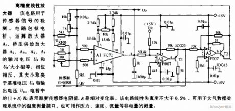
The circuit is used to detect sensor signal. The circuit consists of bridge, operational amplifier A1, bridge voltage supply amplifier A2,A3. The output voltage UR,UR' of A2,A3 have the same value and opposite phases. Their values are decided by the base voltage UR and output voltage UO. In the bridge, (1+δ)R4 stands for the resistance value of the temperature sensor. δ is the relative variable ratio.The circuit's linear distortion is not larger than 0.5%, which can be use as the temperature measurement interface in air data processing system. It can also be used to measure the non electrical quantity such as pressure, speed and flow rate. (View)
View full Circuit Diagram | Comments | Reading(875)
MOSFET Tube Drive Digital Modulation Output Circuit
Published:2011/7/18 3:02:00 Author:Sue | Keyword: MOSFET Tube, Drive, Digital Modulation, Output
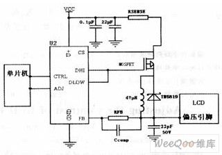
The picture shows the MOSFET tube drive digital modulation output circuit. (View)
View full Circuit Diagram | Comments | Reading(1057)
Dual Track Loudspeaker Protection Circuit
Published:2011/7/18 0:46:00 Author:Sue | Keyword: Dual Track, Loudspeaker, Protection
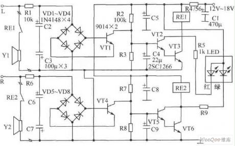
The picture shows the dual track loudspeaker protection circuit. It is designed that the left and right tracks are working independently. In the picture(to take the left track for example), R2, C4 and VT2,VT3 compose starting delay circuit which can prevent the large starting current from shocking the loudspeaker.
Component choice:We can choose Φ3mm high-brightness two-tone LED as LED. Because of the reason that LED has different working currents, so R5,R9 have adjustable parameters. At the same time, LED and current-limiting resistor R5,R9 are connected to relay RE1,RE2 in parallel, which can prevent inverse peak voltage and can prevent VT2,VT3,VT5,VT6 frombeing punctured. The best choice for C4,C9 is low-leakage tantalum capacitor. (View)
View full Circuit Diagram | Comments | Reading(1927)
| Pages:34/54 At 202122232425262728293031323334353637383940Under 20 |
Circuit Categories
power supply circuit
Amplifier Circuit
Basic Circuit
LED and Light Circuit
Sensor Circuit
Signal Processing
Electrical Equipment Circuit
Control Circuit
Remote Control Circuit
A/D-D/A Converter Circuit
Audio Circuit
Measuring and Test Circuit
Communication Circuit
Computer-Related Circuit
555 Circuit
Automotive Circuit
Repairing Circuit