
Audio Circuit
Index 24
Audio_mlxer
Published:2009/7/22 22:08:00 Author:Jessie
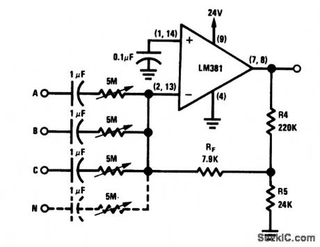
In many audio applications,it is desirable to provide a mixer tocombine or select several inputs,Such applications include public-address systems,where more than one microphone is used,tape recorders,hi-fi phonographs,guitar amplifiers,etc.This circuit provides for mlxlng of 600-Ω dynamic microphones, each with an output level of 10 mV The circuit operates from a 24-V Supply and delivers 5-V output,with a dynamic range of 80 dB. (View)
View full Circuit Diagram | Comments | Reading(1896)
Diode_diode_coupler
Published:2009/7/22 22:00:00 Author:Jessie
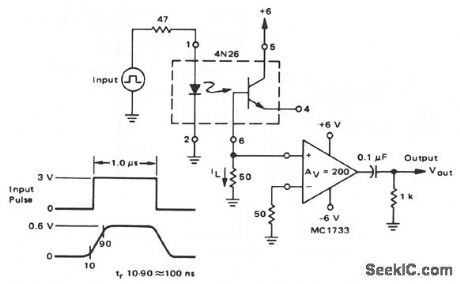
This circuit shows a 4N26 that is used as a diode/diode coupler. The 4N26 emitter is left open, the load resistor is connected between base and ground, and the collector is tied to the supply. Using the 4N26 in this way reduces the switching time from about 2 or 3 μs to 100 ns. (View)
View full Circuit Diagram | Comments | Reading(3902)
Discrete_component_audio_amplifier_7_to_35_W
Published:2009/7/22 4:07:00 Author:Jessie
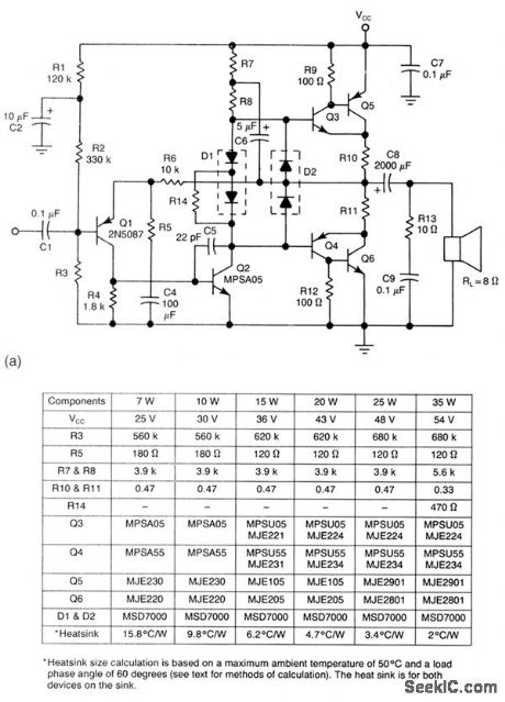
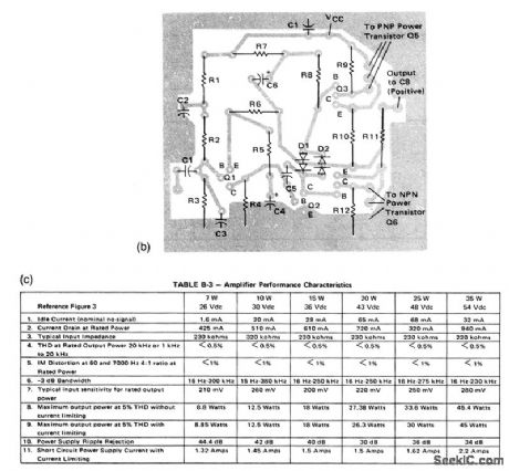
This circuit provides a 7- to 35-W output, depending on power source and component values (as shown), with overload protection. Figures 1-18B and 1-18C show the PC-board layout and performance characteristics, respectively. (View)
View full Circuit Diagram | Comments | Reading(1206)
Discrete_component_audio_amplifier_3_to_5_W_npn_driver
Published:2009/7/22 4:05:00 Author:Jessie
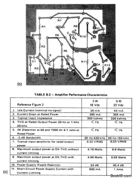
This circuit provides a 3- or 5-W output, depending on power source and component values, with an npn driver, and overload protection. Figures 1-17B and 1-17C show the PC-board layout and performance characteristics, respectiVely.
(View)
View full Circuit Diagram | Comments | Reading(1127)
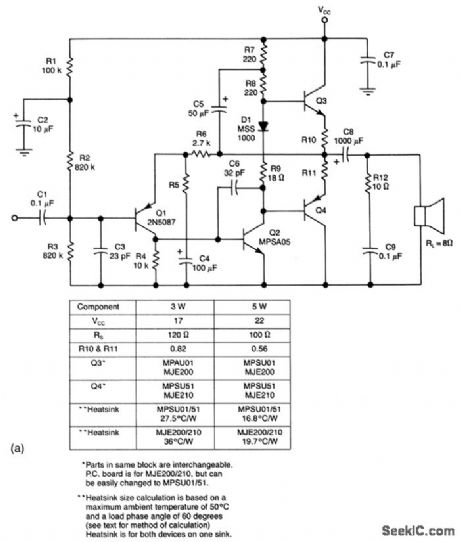
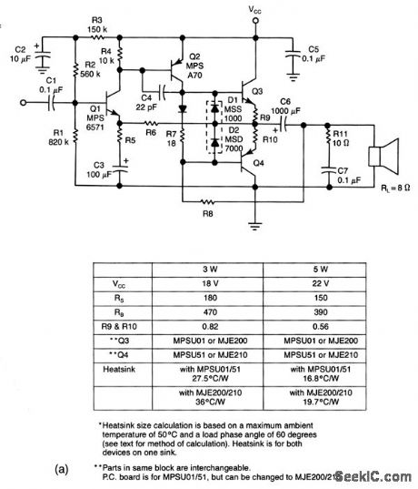
Discrete_component_audio_amplifier_3_to_5_W
Published:2009/7/22 4:03:00 Author:Jessie
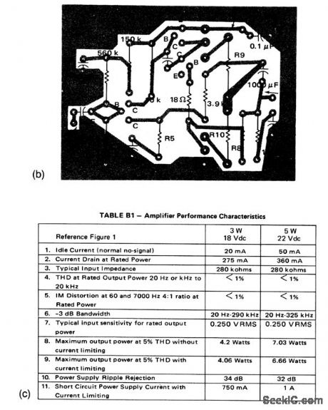
This circuit provides a 3- or 5-W output, depending on power source and component values, with a pnp driver and overload protection. Figures 1-16B and 1-16C show the PC-board layout and performance characteristics, respectively. (View)
View full Circuit Diagram | Comments | Reading(823)
Audio_amplifiers_with_short_circuit_protection
Published:2009/7/22 4:01:00 Author:Jessie
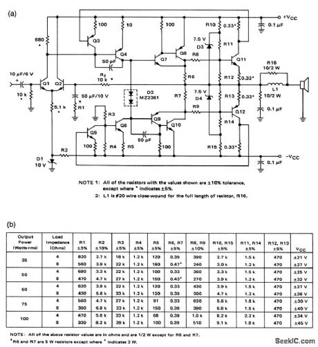
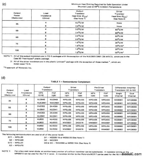
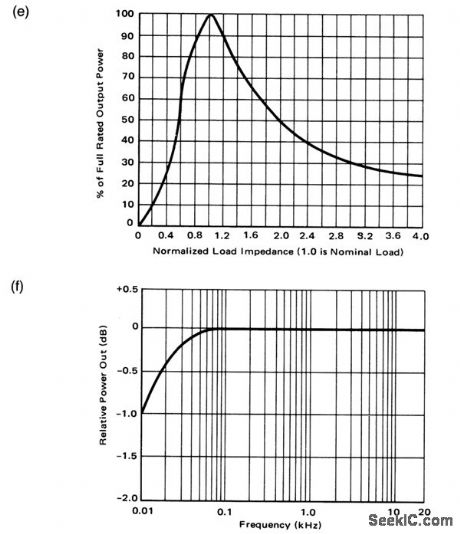
This circuit makes optimum use of economy transistors in discrete-component amplifiers that will operate safely under any usable load conditions, including shorts. Figures 1-15B, 1-15C, and 1-15D show the transistor complement, resistor values/power-supply voltages, and heatsink requirements, respectively, for various power outputs from 35 to 100 W. Input sensitivity is 1 Vrms into 10 kΩ for full-rated output power. Frequency response is less than 3-dB rolloff from 10 Hz to 100 kHz, referenced to t kHz. Power bandwidth is the full-rated output power ±2 dB from 20 Hz to 20 kHz. Figures 1- 15E and 1- 15F show the load sensitivity and power bandwidth. Total harmonic distortion (THD) is less than 0.2% at any power level between 100 mW and full-rated output and at any frequency between 20 Hz and 20 kHz. Inter modulation distortion is less than 0.2% at any power level from 100 mW to the full-rated output (60 Hz and 7 kHz mixed 4 to 1 )
(View)
View full Circuit Diagram | Comments | Reading(1547)
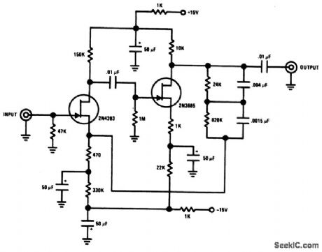
Hi_fi_tone_control_with_high_impedance_input
Published:2009/7/22 5:27:00 Author:Jessie
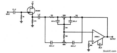
The JFET provides both high input impedance and low noise to buffer an op-amp feedback-type tone control. (View)
View full Circuit Diagram | Comments | Reading(1625)
Amplifier_for_piezoelectric_transducers
Published:2009/7/22 4:32:00 Author:Jessie
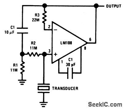
This circuit shows an LM108 amplifier for high-impedance ac transducers, such as a piezoelectric accelerometer. The circuit has input resistance that is much greater than the dc return resistor values. This is accomplished by bootstrapping the resistors to the output. With such an arrangement, the lower cutoff frequency of a capacitive transducer is determined more by the RC output of R1 and C1 than by resistor values and the equivalent capacitance of the transducer. (View)
View full Circuit Diagram | Comments | Reading(3488)
Tone_control_with_20_dB_midband_gain
Published:2009/7/22 4:29:00 Author:Jessie
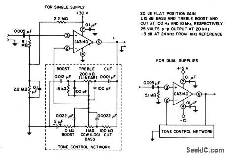
This circuit has boost and cut specifications similar to that of Fig. 1-22.The wideband gain is equal to the ultimate boost or cut, plus one (in this case a gain of 11). For a 20-dB boost and cut, the input loading is essentially equal to the resistance from terminal 3 to ground. (View)
View full Circuit Diagram | Comments | Reading(1091)
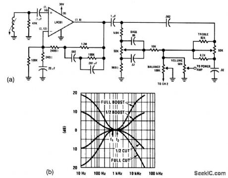
Baxandall_tone_control
Published:2009/7/22 4:28:00 Author:Jessie
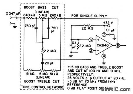
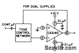
This circuit provides unity gain at midband and uses standard linear potentiometers. Bass/treble, boost, and cut are ±15 dB at 100 Hz and 10 kHz, respectively. Full peak-to-peak output is available up to at least 20 kHz. Amplifier gain is -3 dB down from the flat position (70 kHz). (View)
View full Circuit Diagram | Comments | Reading(0)
12_W_audio_amplifier_with_discrete_output_and_IC_input
Published:2009/7/22 4:25:00 Author:Jessie
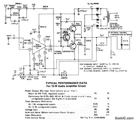
This circuit has a true complementary-symmetry output with a programmable IC amplifier input. (View)
View full Circuit Diagram | Comments | Reading(1027)
Discrete_component_Darlington_audio_amplifier
Published:2009/7/22 4:21:00 Author:Jessie

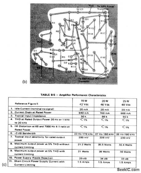
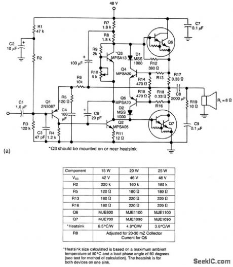

This circuit provides a 15-, 20-, or 25-W output, depending on the power source and component values (as shown), with overload protection, using Darlingtons in the output stages. Figures 1-20B and 1-20C show the PC-board layout and performance characteristics, respectively. (View)
View full Circuit Diagram | Comments | Reading(2944)
NAB_tape_preamp_with_fast_turn_on
Published:2009/7/22 20:34:00 Author:Jessie
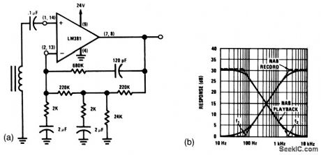
This circuit requires only 0.1 second for turn-on, Compare to Fig. 1-29.When recording, the frequency response is the complement of the NAB playback equalization, making the composite record and playback response flat (Fig.1 -30B). (View)
View full Circuit Diagram | Comments | Reading(1125)
Typical_tape_playback_amplifier
Published:2009/7/22 20:20:00 Author:Jessie

This circuit requires about 5 seconds to turn on (for the gain and supply voltages shown). The turn-on time is approximately
(View)
View full Circuit Diagram | Comments | Reading(897)
Ultra_high_gain_audio_amplifier
Published:2009/7/22 20:18:00 Author:Jessie
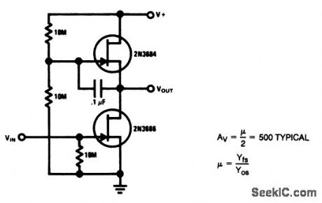
Sometimes called the JFET μ amp, this circuit provides a very low-power, high-gain amplifying function. Because μ of a JFET increases as drain current decreases, the lower drain current is, the more gain you get. However, dynamic range is sacrificed with increasing gain. (View)
View full Circuit Diagram | Comments | Reading(0)
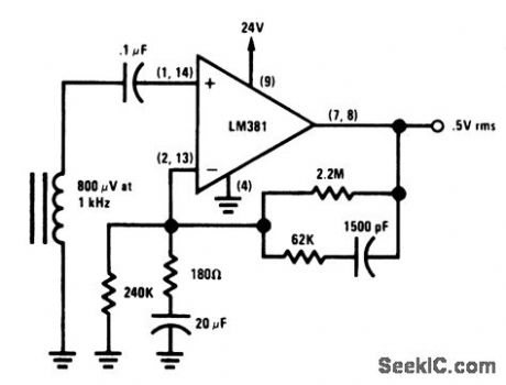
Magnetic_pickup_phono_preamp
Published:2009/7/22 20:16:00 Author:Jessie

This preamplifier provides proper loading to a reluctance-type phono cartridge. The circuit provides about 25 dB of gain at 1kHz (2.2-mV input for 100-mV output), and features S+ S/N ratio of better than -70 dB (referenced to 10-mV input at 1kHz). The feedback provides for RIAA equalization with a dynamic range of 84 dB (reference to 1kHz). (View)
View full Circuit Diagram | Comments | Reading(1270)
Stereo_magnetic_phono_preamp_and_tone_controls
Published:2009/7/22 21:15:00 Author:Jessie
This circuit requires only 0.1 second for turn-on, Compare to Fig. 1-29.When recording, the frequency response is the complement of the NAB playback equalization, making the composite record and playback response flat (Fig.1 -30B). (View)
View full Circuit Diagram | Comments | Reading(1567)
Minimum_component_phono_amp
Published:2009/7/22 22:11:00 Author:Jessie
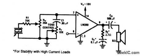
This circuit shows an LM380 power-amplifier IC used as a phono amplifier The circuit has a voltage-divider volume control, with high-frequency rolloff tone control, and provides about 2.5 W to an 8-Ω speaker. (View)
View full Circuit Diagram | Comments | Reading(2000)
Line_operated_IC_audio_amplifier
Published:2009/7/23 21:10:00 Author:Jessie
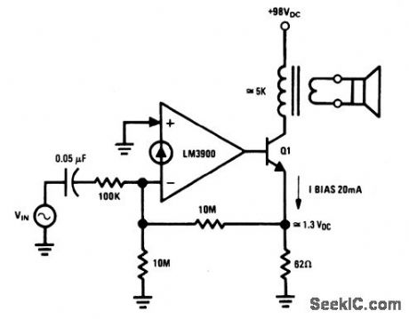
This amplifier operates from a +98-V supply (the rectified line voltage). Such amplifiers are often found in consumer products. Virtually any high-voltage transistor (capable of about 100 V from collector to emitter) can be used for Q1, which is biased and controlled by the LM3900 Norton amplifier (chapter 11). The magnitude of the dc biasing voltage, which appears across the emitter resistor of Q1 is controlled by the resistor between the (-) input of the LM3900 and ground. (View)
View full Circuit Diagram | Comments | Reading(857)
Video_distribution_amplifier_
Published:2009/7/23 20:22:00 Author:Jessie
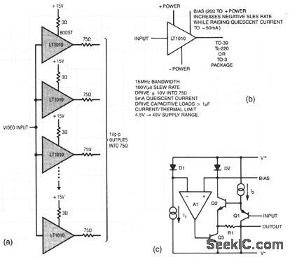
The resistors in the output lines are included to isolate reflections from unterminated lines. If the line characteristics are known, the resistors can be deleted. To meet NTSC gain-phase requirements, a small-value boost resistor is used. Figures 3-27B and 3-27C show the LT1010 characteristics. (View)
View full Circuit Diagram | Comments | Reading(1258)
| Pages:24/54 At 202122232425262728293031323334353637383940Under 20 |
Circuit Categories
power supply circuit
Amplifier Circuit
Basic Circuit
LED and Light Circuit
Sensor Circuit
Signal Processing
Electrical Equipment Circuit
Control Circuit
Remote Control Circuit
A/D-D/A Converter Circuit
Audio Circuit
Measuring and Test Circuit
Communication Circuit
Computer-Related Circuit
555 Circuit
Automotive Circuit
Repairing Circuit