
Audio Circuit
Index 35
Reversed-phase Combiner Amplifier Circuit
Published:2011/7/18 1:10:00 Author:Sue | Keyword: Reversed-phase, Combiner, Amplifier
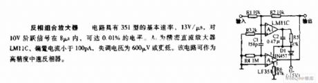
The circuit has a 351-type basic rate of 13V/μs which can reach 0.01% level when 10V step signal is beyond 8μs. A1 is precise direct current amplifier LM11C with a bias current lower than 100pA and a offset voltage equal to or lower than 600μV. The circuit can work as high-precision intermediate speed phase inverter. (View)
View full Circuit Diagram | Comments | Reading(874)
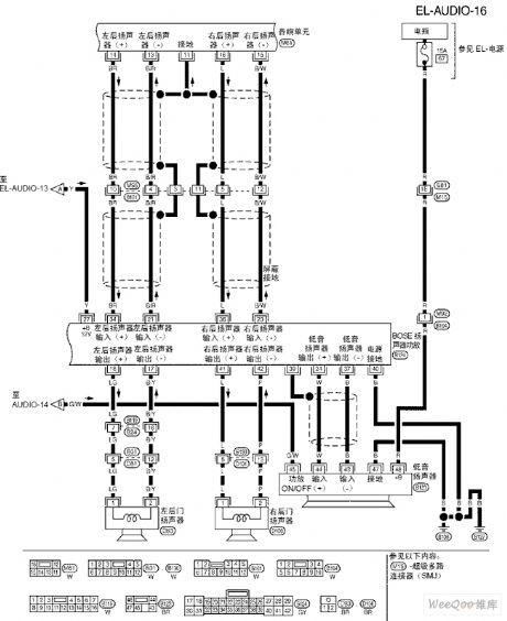
TEANA A33-EL Sound (BOSE System)Circuit Three
Published:2011/7/14 20:58:00 Author:Joyce | Keyword: TEANA , Sound , BOSE System
TEANA A33-EL Sound (BOSE System)Circuit (View)
View full Circuit Diagram | Comments | Reading(794)
TEANA A33-EL Sound (BOSE System)Circuit Six
Published:2011/7/14 20:57:00 Author:Joyce | Keyword: TEANA , Sound , BOSE System
TEANA A33-EL Sound (BOSE System)Circuit (View)
View full Circuit Diagram | Comments | Reading(796)
TEANA A33-EL Sound (BOSE System)Circuit Five
Published:2011/7/14 20:56:00 Author:Joyce | Keyword: TEANA , Sound , BOSE System
TEANA A33-EL Sound (BOSE System)Circuit (View)
View full Circuit Diagram | Comments | Reading(749)
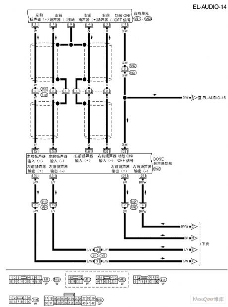
TEANA A33-EL Sound (BOSE System)Circuit Four
Published:2011/7/14 20:55:00 Author:Joyce | Keyword: TEANA , Sound , BOSE System
TEANA A33-EL Sound (BOSE System) Circuit (View)
View full Circuit Diagram | Comments | Reading(771)
TEANA A33-EL Sound (BOSE System)Circuit Two
Published:2011/7/14 20:54:00 Author:Joyce | Keyword: TEANA , Sound , BOSE System
TEANA A33-EL Sound (BOSE System)Circuit (View)
View full Circuit Diagram | Comments | Reading(760)
TEANA A33-EL Sound (BOSE System)Circuit One
Published:2011/7/14 20:53:00 Author:Joyce | Keyword: TEANA , Sound , BOSE System
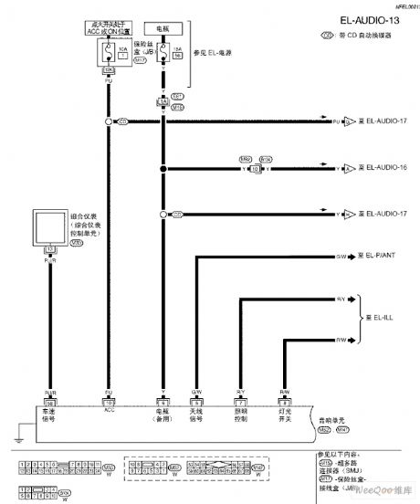
TEANA A33-EL Sound (BOSE System)Circuit (View)
View full Circuit Diagram | Comments | Reading(744)
TEANA A33-EL Sound Remote Control Circuit
Published:2011/7/14 20:51:00 Author:Joyce | Keyword: TEANA , Sound, Remote Control
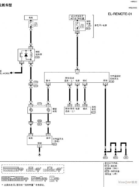
TEANA A33-EL Sound Remote Control Circuit (View)
View full Circuit Diagram | Comments | Reading(713)
High Quality Dual Channel Mega Bass Circuit
Published:2011/7/15 1:40:00 Author:Joyce | Keyword: High Quality , Dual Channel, Mega Bass
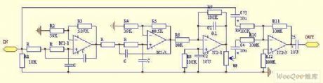
Principle of the circuit: After the input signal goes through low pass processing with changing slope of 24 db/oc by a four-order low pass filter composed of IC1-1 and other peripheral components (fc = 70 Hz, A = 8.2 db in the circuit), it is buffered and amplified for 10 times by the inverting AC amplifier which is IC2-1 centered before it is output. Low frequency signals which have been greatly enhanced and the original signals will be sent to IC2-3 through C4, C3 respectively to be mixed, and the mixed signals will be output via C5. W controls the mixing amount of low frequency signals and original signals. In order to guarantee the output signals through C5 are authentic when W is shut up, its gain at this stage is set to be 0 dB.
(View)
View full Circuit Diagram | Comments | Reading(3158)
AN262—the record/playback preamplifier integrated circuit
Published:2011/7/15 21:31:00 Author:Borg | Keyword: record/playback preamplifier, integrated circuit
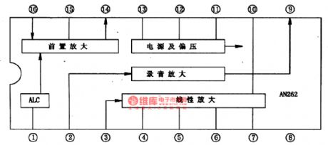
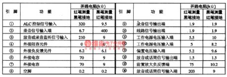
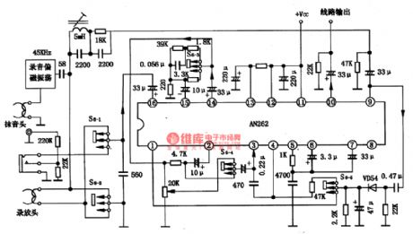
AN262 is a record/playback preamplifier integrated circuit produced by Panasonic, which is used in radios and video recorders, it is also used in compounded stereos.1. the internal circuit and pin functionsAN262 contains the playback and microphone preamplifier circuit, ALC circuit, recording amplifier circuit, playback amplifier circuit, power supply circuit and so on. The IC is in 16-pin dual-line amplifier circuit, whose internal circuit is shown in figure 1 and pin functions and data in table 1.
(View)
View full Circuit Diagram | Comments | Reading(2308)
AN26OP AM frequency converter and FM/AM integrated circuit
Published:2011/7/17 21:56:00 Author:Borg | Keyword: frequency converter, integrated circuit
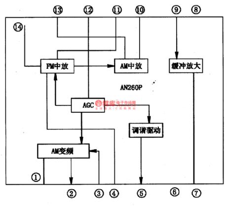
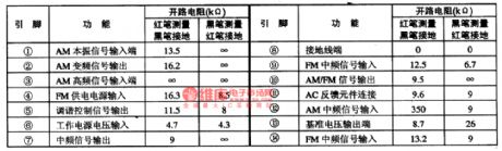
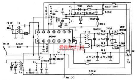
The AN260P is the AM frequency transmission, FM and AM INTREQ integrated circuit, which is used in radios, recorders and grouped stereo circuits.1. the internal circuit and pin functions of AN260PAN260P contains the tuning indication drive, voltage stabilizer, FM intermediate frequency amplifier and AGC amplifier circuit. FM and AM intermediate amplifiers are both connected with the filter.AN260P is in the 14-pin dual in-line package, whose internal circuit is in figure 1.
(View)
View full Circuit Diagram | Comments | Reading(2073)
AK4524—the digit audio signal decoding integrated circuit
Published:2011/7/17 22:04:00 Author:Borg | Keyword: signal decoding, integrated circuit
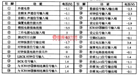
AK4524 is a digit audio signal decoding integrated circuit produced by Panasonic, which is used in Sony PIP color TV sets.\ AK4524 contains the digit audio signal decoding and D/A converter, and it is fixed with the shift circuit. When the IC is used in Sony SCC-P33DA/CA, the pin functions and data of the circuit is listed in table 1.
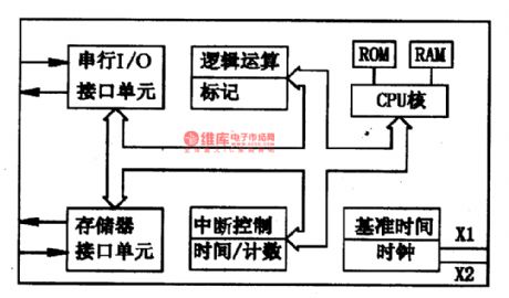
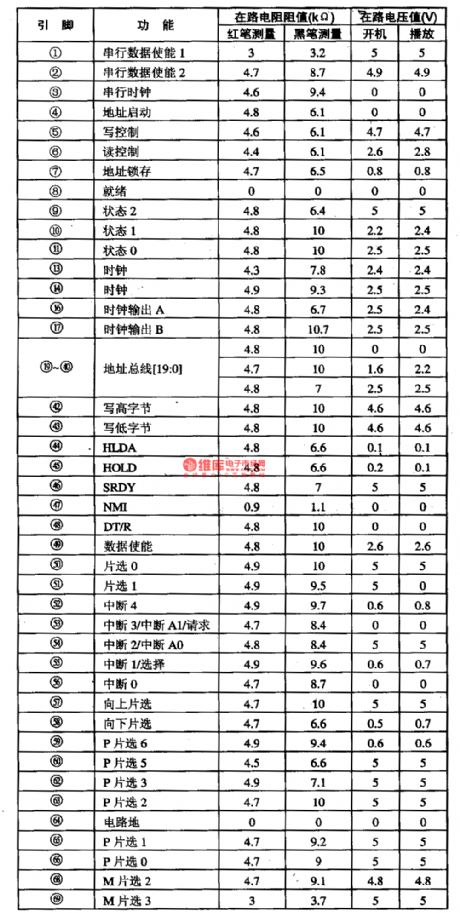
The AMl86ZM25KC single chip microcomputer integrated circuitAMl86ZM25KC is a 16-bit CMOS specific microcomputer integrated circuit.
(View)
View full Circuit Diagram | Comments | Reading(1216)
IAP722-the FM high frequency resonance integrated circuit
Published:2011/7/15 21:07:00 Author:Borg | Keyword: high frequency, resonance integrated circuit
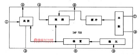
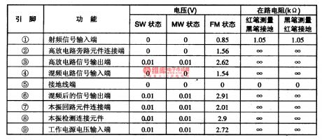
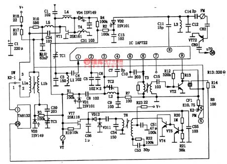
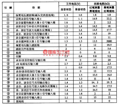
IAP722 is a FM high frequency resonance integrated circuit, which is used in low voltage radios and walkmen.1. the internal circuit and pin functions of IAP722IAP722 contains the FM AGC, local oscillation, mix, buffering amplifier and other circuits. The IC is in 9-pin single line package, whose internal circuit is shown in figure 1-1, and pin functions and data is listed in table 1-1.
Figure 1-1 the internal circuit of IAP722Table 1-1 pin functions and data of IAP722
2. the typical application circuit of IAP722
(View)
View full Circuit Diagram | Comments | Reading(979)
the bridge sidetone removing circuit
Published:2011/7/17 22:07:00 Author:Borg | Keyword: bridge, sidetone removing
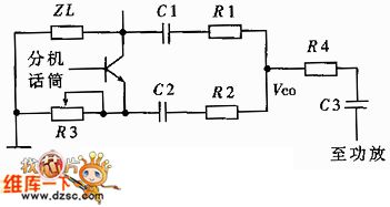
The bridge sidetone removing circuit is shown as above.
(View)
View full Circuit Diagram | Comments | Reading(829)
The phase offset sidetone circuit
Published:2011/7/17 22:11:00 Author:Borg | Keyword: phase offset, sidetone
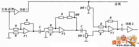
The phase offset sidetone circuit is shown as above.
(View)
View full Circuit Diagram | Comments | Reading(819)
The acousto-optic circuit diagram of electron gun targeting
Published:2011/6/23 23:01:00 Author:Nicole | Keyword: acousto-optic, electron gun, targeting

The optical control monostable trigger circuit is composed of 555 and luminescence resistance RG, RP, R2, C1. When there is no light, RG is high resistance, time base circuit 555's 3 foot is low level, then LED1, LED2 which have blue light are lighted, the audio circuit does not work; when the infrared beam which is emitted by infrared electron gun hits the uminescence resistance RG of the small hole's target circuit, RG turns to low resistance, 555's 2 foot is low level(<1/3 VDD), the monostable circuit reverses, 3 foot turns to high level, then LED3, LED4(blue)are turned off, LED3, LED4(green)are turned on, at the same time, the audio circuit is triggered, it sends out sound. The acousto-optic duration time is decided by the temporary stability time of the monostable circuit, namely, td=1.1R2C1.
(View)
View full Circuit Diagram | Comments | Reading(1174)
CX20023--the single chip stereo playback integrated circuit
Published:2011/7/12 3:36:00 Author:Borg | Keyword: single chip, stereo, playback, integrated circuit
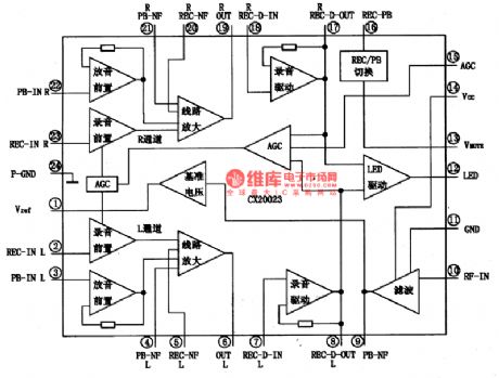
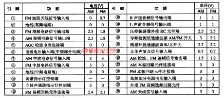
CX20023 is a single chip stereo record/playback integrated circuit, which is often used in walkmen and domestic stereos.1.the internal circuit and pin functions of CX20023CX20023 contains two lines of same microphone recording preamplifier and wire recording amplifier, tape playback balance amplifier, recording LEV auto control and other circuits, whose internal circuit is shown in figure 1. This IC is in the pin in-line plastic structure package, whose pin functions and data are listed in table 1.
(View)
View full Circuit Diagram | Comments | Reading(1170)
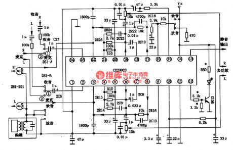
KA2292-the single chip stereo radio integrated circuit
Published:2011/7/12 7:38:00 Author:Borg | Keyword: single chip, stereo radio

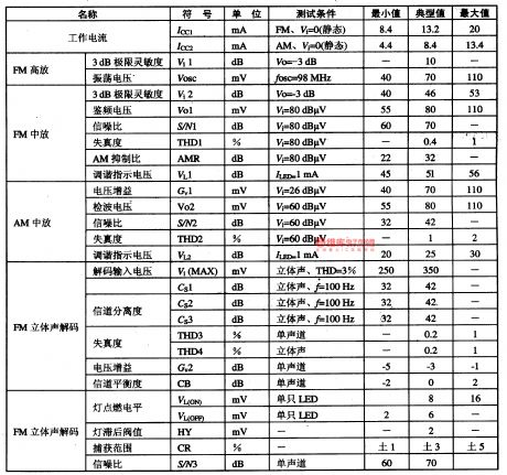
1. Main functions of KA2292 The FM part of KA2292 includes circuits of FM high-frequency amplifier, local machine oscillating FM mix, FM INTREQ, modulation orthographic discrimination, FM tuning indicator, audio amplifier and so on. The AM part of KA2292 includes circuits of high frequency amplifier, local oscillation, AM mix, AM INTREQ, AM detection, AGC producing, AM tuning indicator and audio amplifier, etc. The stereo sound decoding part of KA2292 includes circuits of PLL amplifier, phase comparing and so on.
(View)
View full Circuit Diagram | Comments | Reading(1757)
K9450M--the sound 1st intermediate bandpass filter integrated circuit
Published:2011/7/13 21:24:00 Author:Borg | Keyword: intermediate bandpass, integrated circuit
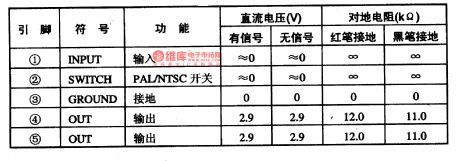
K9450M is the sound 1st intermediate bandpass filter integrated circuit, which is widely used in Konka large screen color TV set of S serial.1.function featuresK9450M integrated circuit contains PAL/NTSC switch control circuit, sound 1st intermediate bandpass filter circuit and other additional function circuits, K9450 is often working with K627K/D, which is used to separate the sound and picture signals, so the sharpness of the picture and the purity of the sound can be improved.2.pin functions and dataK9450M is in the 5-pin single in-line package.
(View)
View full Circuit Diagram | Comments | Reading(717)
TEANA A33-EL Lighting Circuit Five
Published:2011/7/14 9:17:00 Author:Joyce | Keyword: TEANA , Lighting
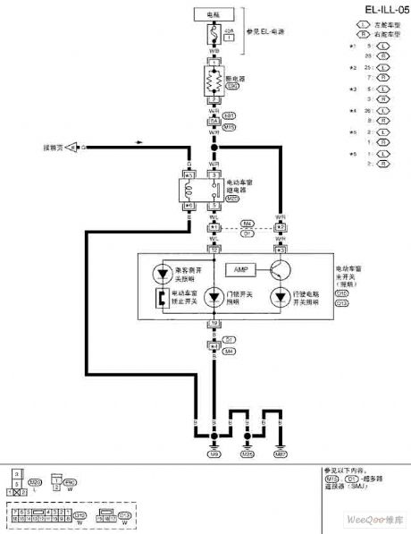
TEANA A33-EL Lighting Circuit (View)
View full Circuit Diagram | Comments | Reading(625)
| Pages:35/54 At 202122232425262728293031323334353637383940Under 20 |
Circuit Categories
power supply circuit
Amplifier Circuit
Basic Circuit
LED and Light Circuit
Sensor Circuit
Signal Processing
Electrical Equipment Circuit
Control Circuit
Remote Control Circuit
A/D-D/A Converter Circuit
Audio Circuit
Measuring and Test Circuit
Communication Circuit
Computer-Related Circuit
555 Circuit
Automotive Circuit
Repairing Circuit