
Audio Circuit
Index 39
Multifunctional Music Doorbell Circuit
Published:2011/7/8 1:30:00 Author:Joyce | Keyword: Multifunctional, Music Doorbell
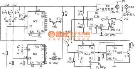
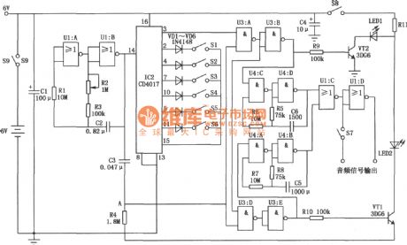
Multifunctional music doorbell has three functions.First, it can set a password; second, it has the function of avoiding disturbance; thirdly, it can inform whether the host is in. The circuit is as shown in the figure. It constitutes of a password setting circuit, control switch and doorbell music circuit. IC1,IC2 is CD4017; IC3a is one flip-flop of the double D flip-flop CD4013. It composes a monostable trigger with R8, C4 . (View)
View full Circuit Diagram | Comments | Reading(985)
Touch Flash Buzzer Circuit
Published:2011/7/8 2:48:00 Author:Joyce | Keyword: Touch , Flash , Buzzer
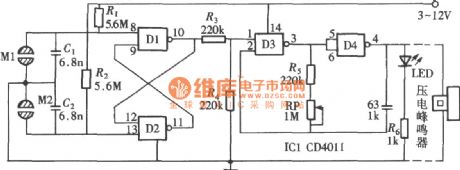
As shown in the circuit is a touch flash buzzer circuit composed of a four-two input end NAND gate CD4011. (View)
View full Circuit Diagram | Comments | Reading(1073)
Multitone Buzzer Circuit
Published:2011/7/8 3:38:00 Author:Joyce | Keyword: Multitone, Buzzer
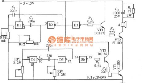
As shown in the figure, the multitone buzzer is composed of a six inverse buffer converter CD4049.It can produce a lot of tones if it is adjusted. In this circuit, four gates of CD4049 form two groups of multivibrator respectively. The buzzer will produce sound after being driven by output of the logic control gate after buffering and transforming. (View)
View full Circuit Diagram | Comments | Reading(1412)
Electronic Music Box Circuit
Published:2011/7/8 3:55:00 Author:Joyce | Keyword: Electronic , Music Box
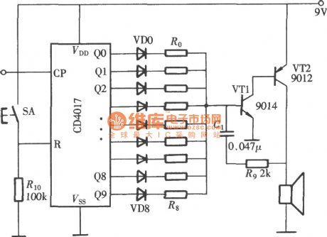
As shown in the figure is an electronic music box circuit composed of CD4017 (View)
View full Circuit Diagram | Comments | Reading(4124)
Unbalanced transmission mode circuit diagram
Published:2011/6/26 13:17:00 Author:Sophia | Keyword: Unbalanced transmission mode
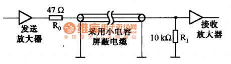
(View)
View full Circuit Diagram | Comments | Reading(797)
buffer circuit of isolated capacitive load of OPA606
Published:2011/7/7 1:10:00 Author:chopper | Keyword: buffer, isolated, capacitive load
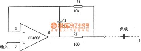
The picture shows the buffer circuit of isolated capacitive load.The general operational amplifier will greatly effect the circuit stability,and its dynamic performance will decline seriously when it is connected to capacitive load.However,the circuit shown in picture is able to drive capacitive loads,because the circuit uses the FET input-based media isolation broadband op-amp OPA606 to form amplifier,and to idealized the load ability of amplifition circuit. (View)
View full Circuit Diagram | Comments | Reading(1225)
TA8105N monolithic stereo playback integrated circuit
Published:2011/7/5 1:12:00 Author:chopper | Keyword: monolithic, stereo, playback, integrated circuit
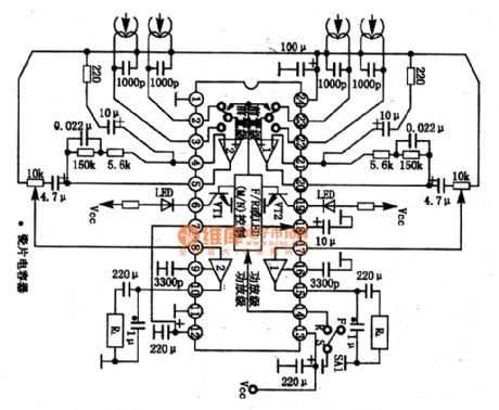
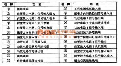
TA8105N is a monolithic playback integrated circuit produced by Company TOSHIBA,and it is applied to mini acoustic system like low-voltage walkman and so on.1.inner circuit and function of pins The inner circuit of TTA8105/N integrated package includes two same preposing equilibrium amplifier circuits,power amplifier circuit and tape track switching circuit. TTA8105/N integrated circuit is of two package structure,TA8105/N adopts dual inline 2 pinned package,TA8105F adopts dual inline 24 pinned flat package.
(View)
View full Circuit Diagram | Comments | Reading(1692)
The reinforced bass metronome circuit composed of the CD4017
Published:2011/6/14 2:44:00 Author:TaoXi | Keyword: reinforced bass metronome
The bass metronome can reinforce each beat, and it can increase the bass intensities of 2, 3, 4, 6 and 9. This metronomehas thelight display function by using the red LED and green LED, the red LED is used as the lighting instruction of the reinforced bass beat, and the non-reinforced bass beat is instructed by the green LED, so the user can identify which one is the reinforced bass beat easily. The reinforced bass metronome circuit is as shown in the figure. The whole circuit is composed of four CMOS digital integrated circuits. (View)
View full Circuit Diagram | Comments | Reading(1406)
Electrocardiogram (ECG) Amplifying Circuit
Published:2011/7/1 2:41:00 Author:Joyce | Keyword: Electrocardiogram , (ECG) , Amplifying
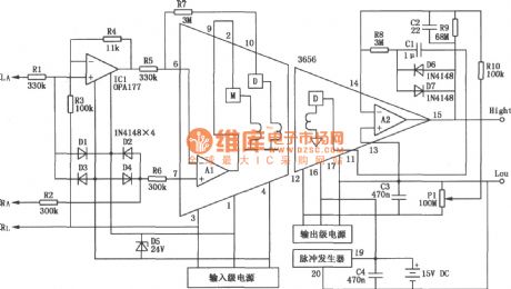
Cardiovascular disease has become a very common disease, and with the speeding pace of life and people’s increasing awareness of life standard and health, they need to exam and protect their hearts at any time and to carry out timely treatment in emergency. As shown in the electrocardiogram (ECG) amplifying circuit, it does not only use transformer coupling isolated amplifier 3656 , but also uses a piece of precision operation amplifier OPA177 (offset voltage≤ 10μV ,the offset voltage drift is 0.1 μV / ℃,the open-loop gain is greater than 130 dB, and the static typical current is 1.5 mA). (View)
View full Circuit Diagram | Comments | Reading(1709)
Mosfet 50 W Audio Power Amplifier Circuit
Published:2011/7/1 3:44:00 Author:Joyce | Keyword: Mosfet , 50 W, Audio, Power Amplifier
As shown in the figure is a Mosfet 50 W audio power amplifier circuit. (View)
View full Circuit Diagram | Comments | Reading(8522)
Mosfet 80 W Audio Power Amplifier Circuit
Published:2011/7/1 3:42:00 Author:Joyce | Keyword: Mosfet, 80 W , Audio , Power Amplifier
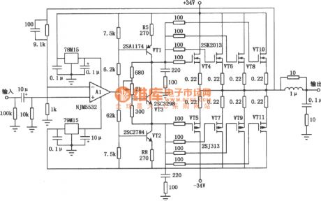
As shown in the figure is a Mosfet 80 W audio power amplifier circuit. (View)
View full Circuit Diagram | Comments | Reading(7741)
500W Transistor Power Amplifier Circuit
Published:2011/7/1 3:40:00 Author:Joyce | Keyword: 500W , Transistor , Power Amplifier
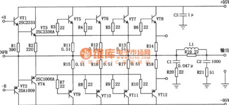
As shown in the figure is a 500W transistor power amplifier circuit. (View)
View full Circuit Diagram | Comments | Reading(14740)
Mosfet Power Amplifier Circuit
Published:2011/7/1 3:35:00 Author:Joyce | Keyword: Mosfet, Power Amplifier

As shown in the figure is a power amplifier circuit consisting of MOSFET tube.The second differential motion in the circuit uses medium power MOSFET 2SJ77 , and the current mirror circuit uses 2SK214. The working current is 6 mA. Since the voltage of power supply is high( ±50V), the transistor will get hot, so a small radiator should be connected. (View)
View full Circuit Diagram | Comments | Reading(6455)
100W Mosfet Power Amplifier Circuit
Published:2011/7/1 3:12:00 Author:Joyce | Keyword: Mosfet, power amplifier
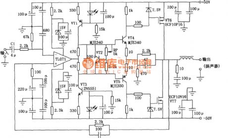
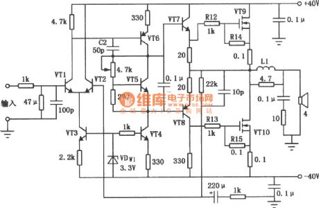
MOSFET power amplifier circuit is mainly used in high-power AV circuits. As shown in the figure is the 100 W MOSFET power amplifier circuit. The input stage of the circuit uses JEFT input op-amp TL071, which has a high input impedance and conversion rate. VT1 and VT3 are complementary constant current source loads of op-amp TL071. VT4 and VT5 compose a typical driver stage, and it has a good linearity and fast response. The output stage VT6 and VT7 use MOSFET tube. They have beautiful timbre and the amplification factor is 5. C1 uses metallized polypropylene capacitor to avoid distortion. (View)
View full Circuit Diagram | Comments | Reading(11545)
The FM l2 wave band radio circuit of Desheng ll9700
Published:2011/7/3 22:28:00 Author:Borg | Keyword: wave band, Desheng
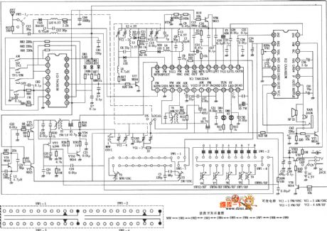
The FM l2 wave band radio circuit of Desheng ll9700 is shown as above.
(View)
View full Circuit Diagram | Comments | Reading(1451)
LA3160 audio IC circuit
Published:2011/7/1 0:55:00 Author:TaoXi | Keyword: audio IC

The LA3160 audio IC circuit is as shown in the figure:
(View)
View full Circuit Diagram | Comments | Reading(3037)
LA3161 audio IC circuit
Published:2011/7/1 0:58:00 Author:TaoXi | Keyword: audio IC
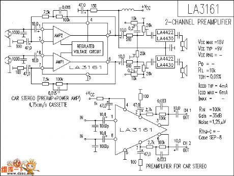
The LA3161 audio IC circuit is as shown in the figure:
(View)
View full Circuit Diagram | Comments | Reading(4278)
LA3220 audio IC circuit
Published:2011/7/1 1:06:00 Author:TaoXi | Keyword: audio IC
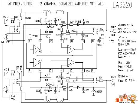
The LA3220 audio IC circuit is as shown in the figure:
(View)
View full Circuit Diagram | Comments | Reading(3637)
The vehicle loudspeaker circuit
Published:2011/6/30 5:02:00 Author:Seven | Keyword: vehicle loudspeaker
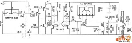
In the figure is the vehicle loudspeaker circuit. The left side of the figured dotted line is the loudspeaker circuit of the former car, SI is the key of the loudspeaker on the steering wheel. S2 is the added single-pole double-throw switch, which is used in the shift of the electric loudspeaker and the audio loudspeaker in the former car. The the switch S is at the position of 2 , by pressing the switch SI, the capacitor Cl is charged, the triodes of VT1 and VT2 are conducting, the relay JI is pulling in, and the normally open connector J1-1 is closed and offers power to the circuit for 15s. IC1 is the specialized audio integrated circuit HL-169, whose working time is 2.8s.
(View)
View full Circuit Diagram | Comments | Reading(886)
The audio control circuit of HN911
Published:2011/6/30 4:50:00 Author:Seven | Keyword: audio control
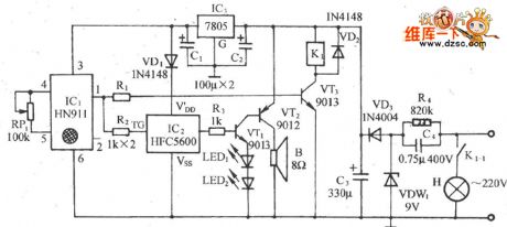
See as the figure, the circuit consists of the heat releasing infrared detection module, relay control light circuit, curses making circuit and AC step-down rectifier circuit, etc. When there are people coming in the chapel, the internal lighting lamp is glowing automatically and the Buddhist scriptures sound is generated; when the people are out, the light and sound are both gone. The circuit can be used in the chapel and sutra mansion for automatic duty and anti-thief.
(View)
View full Circuit Diagram | Comments | Reading(1020)
| Pages:39/54 At 202122232425262728293031323334353637383940Under 20 |
Circuit Categories
power supply circuit
Amplifier Circuit
Basic Circuit
LED and Light Circuit
Sensor Circuit
Signal Processing
Electrical Equipment Circuit
Control Circuit
Remote Control Circuit
A/D-D/A Converter Circuit
Audio Circuit
Measuring and Test Circuit
Communication Circuit
Computer-Related Circuit
555 Circuit
Automotive Circuit
Repairing Circuit