
Audio Circuit
Index 25
Minimum_component_RIAA_phono_amp
Published:2009/7/23 20:07:00 Author:Jessie
This circuit shows an LM380 used as a phono amplifier with RIAA playback characteristics. Figure 1-36B shows the playback response. (View)
View full Circuit Diagram | Comments | Reading(1061)
Minimum_component_phono_amp_with_common_mode_volume_and_tone_controls
Published:2009/7/23 20:06:00 Author:Jessie
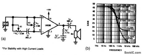
This circuit has a distinct advantage over the circuit of Fig. 1 -33. When transducers of high source-impedance are used, the full input impedance of the amplifier is realized. The circuit also has an advantage with transducers of low source impedance because the signal attenuation of the input voltage divider is eliminated.Figure 1 -35B shows the tone-control response. (View)
View full Circuit Diagram | Comments | Reading(981)
Minimum_component_phono_amp_with_common_mode_volume_control
Published:2009/7/23 1:36:00 Author:Jessie
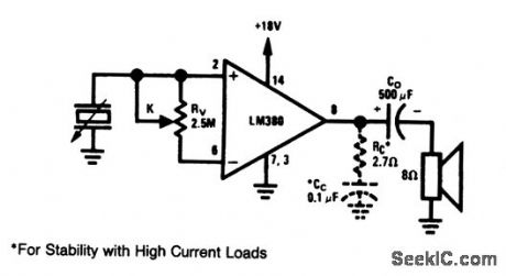
This circuit shows an LM380 as a phono amplifier with common-mode volume control.When in the full-volume position, the only source-loading impedance is the IC input impedance. This reduces to one-half the amplifier input impedance at the zero-volume position. (View)
View full Circuit Diagram | Comments | Reading(974)
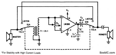
Minimum_component_intercom
Published:2009/7/23 20:19:00 Author:Jessie

With switch S1 in the Talk position, the master-station speaker acts as the microphone. A T1 turns ratio of25 and an IC gain of 50 allows a maximum loop gain of 1250. RV provides a common-mode volume control. Switching S1 to Listen reverses the role of the master and remote speakers. Nationd Sem conductor Linear Appficatons Handbook 1991, p 200. (View)
View full Circuit Diagram | Comments | Reading(1123)
High_frequency_video_switch
Published:2009/7/23 20:19:00 Author:Jessie
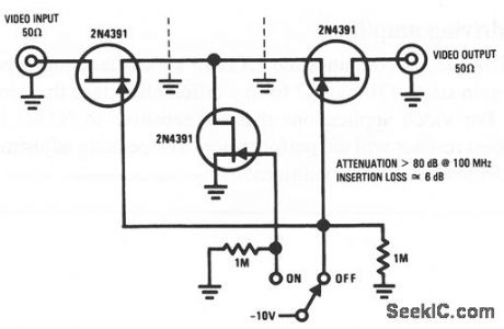
This circuit is similar to that of Fig. 3-22, except that this circuit is used when complete attenuation (rather than variable gain) is required in video applications. The 2N4391 provides a low on-resistance of 30Ωand a high off-impedance. With proper layout (separating input from output by the maximum allowable distance), and an ideal switch, the attenuation and insertion loss shown can be achieved with no difficulty. (View)
View full Circuit Diagram | Comments | Reading(916)
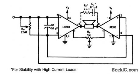
Minimum_component_bridge_amplifier_with_voltage_divider_input
Published:2009/7/23 20:18:00 Author:Jessie
This circuit shows a bridge-amplifier configuration with a voltage-divider input (rather than the common-mode input of Fig. 1-37). With the circuit of Fig. 1-39, if the source voltage Vs (pin 14) is more than 3 inches from the power-source filter capacitor, pin 14 should be decoupled with a 1-μF tantalum capacitor. (View)
View full Circuit Diagram | Comments | Reading(1571)
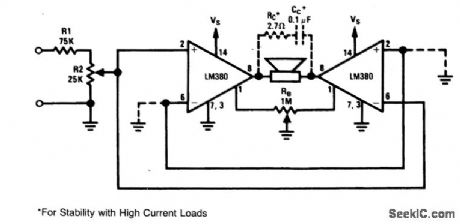
Minimum_component_bridge_amplifier_with_quiescent_balance_control
Published:2009/7/23 20:14:00 Author:Jessie
The quiescent output voltage of the LM380 is specified at 9 ±1V with an 18-V supply. Therefore, under worst-case conditions, it is possible for the circuit of Fig. 1-37 to have 2-V across the load. With an 8-Ω speaker, this 0.25 A of direct current might be excessive. Three alternatives are available:1) take care to match the quiescent voltages, 2) use a non-polar capacitor in series with the load (speaker), 3) use the offset balance control (Fig. 1-38). (View)
View full Circuit Diagram | Comments | Reading(893)
Video_voltage_follower
Published:2009/7/23 20:28:00 Author:Jessie
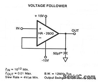
This circuit uses an HA-2600 wideband op amp with very high input impedance and low output impedance. The load capacitor is recommended to prevent high-frequency oscillations (possibly from external wiring). Capacitor values up to 100 pF have little effect on bandwidth or glow rate. Figure 3-29B shows an offset adjustment (if required). (View)
View full Circuit Diagram | Comments | Reading(803)
Precision_high_speed_op_amp_for_video_applications
Published:2009/7/23 20:24:00 Author:Jessie
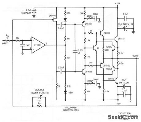
This circuit features a 1500-V/μs slew rate, full output to 8 MHz, ±10-V drive into a 10-Ω load, and is short-circuit protected at ± 1 A. RF layout techniques and a ground plane are mandatory, and the 2N4440s must have heatsinks. The 200-Ω resistors are adjusted for best square-wave output. The 15- to 60-pF peaking-capacitor adjustment should be optimized under loaded output conditions.
(View)
View full Circuit Diagram | Comments | Reading(1055)
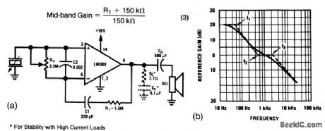
Boosted_gain_amplifier
Published:2009/7/23 20:22:00 Author:Jessie
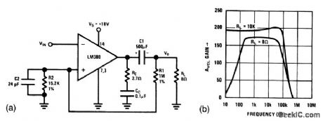
For applications that require gains higher than the internally set gain of 50, it is possible to apply positive feedback around the LM380 for closed-loop gains of up to 300. As shown in Fig. 1-41B, this circuit has a gain of about 200 (well beyond the audio range) when the load is 10 kΩ. When the load is a typical 8-Ω speaker, the circuit provides a gain of over 170 (beyond the audio range). (View)
View full Circuit Diagram | Comments | Reading(1343)
Noncomplementary_audio_noise_reduction_system
Published:2009/7/23 21:15:00 Author:Jessie
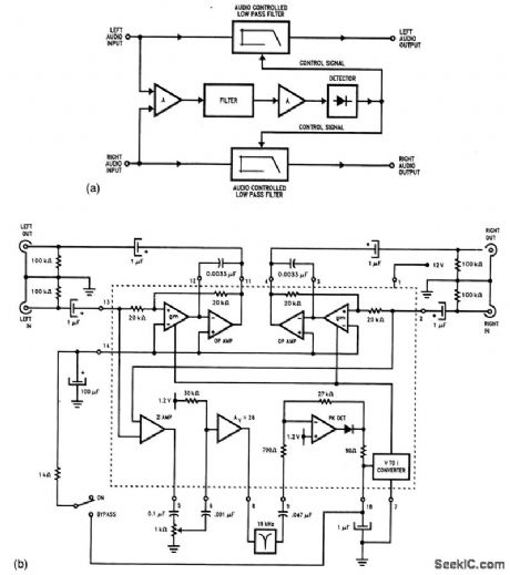
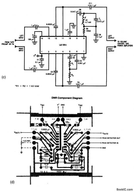
Figure 1-49A shows the block diagram, and Figs. 1-49B and 1-49C show the full schematic details of noncomplementary or dynamic noise-reduction (NR) systems. Complementary NR systems require that certain frequencies be emphasized during recording, then de-emphasized during playback in a comple-mentary mode. That is, if highs are emphasized during recording, highs are de-emphasized during playback. These noncomplementary circuits can be applied to any stereo audio system, without regard as to how the material was recorded.Both the left and right audio paths are controlled by signals derived from the mixed audio input (after filtering, amplification, and detection), all of which occurs in the LM1894. The circuits must be placed immediately after the source preamp, and before any circuit that includes user controls (volume, tone, etc.). L8 in Fig. 1-49C is part of a 19-kHz notch filter, and is adjusted to remove the FM pilot signal. R1 and R2 in Fig. 1 -49C set overall gain, as does the 1-kΩ pot in Fig. 1-49B. The 1-kΩ pot is adjusted for best noise reduction of a given program material. Figure 1-49D shows the PC layout for the circuit of Fig. 1-49B. (View)
View full Circuit Diagram | Comments | Reading(2540)
Transformerless_microphone_preamplifier_with_low_noise_inputs
Published:2009/7/23 21:13:00 Author:Jessie
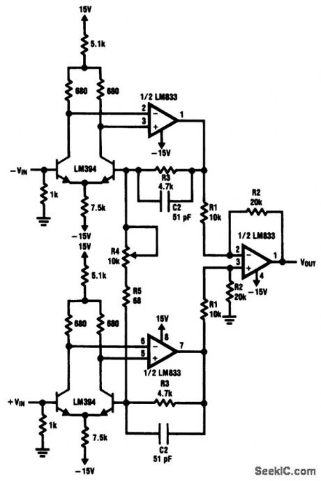
This circuit is similar to that of Fig. 1-47, except that two LM394s are used as input devices for the LM833 gain stages. The equivalent input noise of the Fig. 1-48 circuit is about 340 nV over a 20-Hz to 20-kHz band (-129 dB referred to 1V). (View)
View full Circuit Diagram | Comments | Reading(1632)
Ultra_low_noise_RIAA_preamp
Published:2009/7/23 21:18:00 Author:Jessie
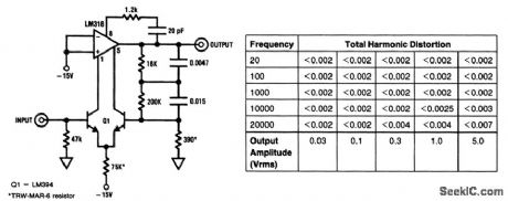
This circuit uses an LM394 and an LM318 to form an ultra-low noise preamp. Noise referred to a 10-mV input signal is -90 dB down, measuring 0.55μV and 70 pA in a 20-kHz bandwidth. The noise figure is less than 2 dB when the amplifier is used with standard phono cartridges, which have an equivalent wideband (20 kHz) noise of 0.7μV. Worst-case dc output offset voltage is about 1V with a 1-kΩ cartridge. THD for various output amplitudes is shown in the table. (View)
View full Circuit Diagram | Comments | Reading(3630)
Dc_coupled_tape_head_preamps_four_head
Published:2009/7/23 21:17:00 Author:Jessie
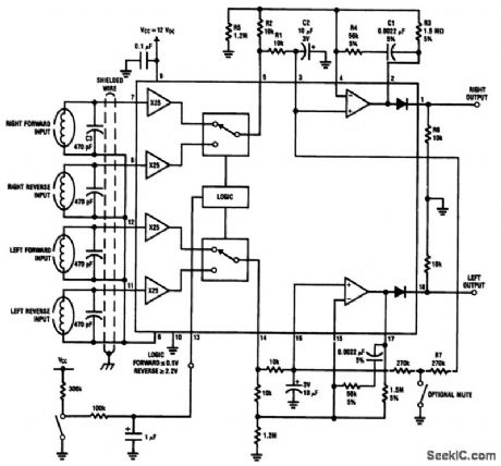
This circuit shows a dc-coupled, four-head stereo preamp using an LM1937. The desired pair of heads (for forward and reverse operation, where the heads are not mechanically repositioned) is controlled by the logic voltage at pin 13. The circuit characteristics are the same as for the circuit of Fig. 1-50. (View)
View full Circuit Diagram | Comments | Reading(862)
Dc_coupled_tape_head_preamps_two_head
Published:2009/7/23 21:16:00 Author:Jessie
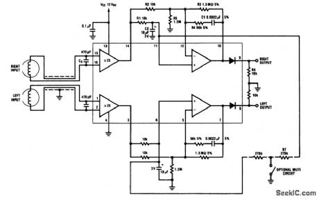
This circuit shows a dc-coupled, two-head stereo preamp using an LM1897. The circuit characteristics are: a GBW of 76 dB at 20 kHz, an S/N ratio of 62 dB (CCIR/ARM), distortion 0.03% at 1kHz, power-supply rejection greater than 95 dB, channel separation of60 dB, and a typical turn-on delay of 0.4 s. (View)
View full Circuit Diagram | Comments | Reading(3005)
Minimum_component_audio_amplifier
Published:2009/7/23 21:21:00 Author:Jessie
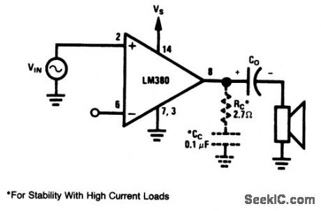
Because the LM380 has internal biasing and compensation, this basic audio amplifier requires only an output-coupling capacitor (typically 500μF). Of course, such an amplifier has no tone- or volume-control (Figs. 1-33 through 1-36).The circuit can supply about 2.5 W into an 8-Ω speaker, with a VS of 12V or greater. The RC and CC components suppress 5- to 10-MHz oscillation that can occur during the negative swing into a high-current load. Although such oscillation will not pass through the speaker, the radiated signals can produce interference in RF-sensitive equipment. (View)
View full Circuit Diagram | Comments | Reading(1540)
Microphone_preamp_with_low_supply_voltage
Published:2009/7/23 21:20:00 Author:Jessie
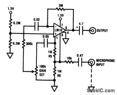
This preamp operates from a single 1.5-V cell, and can be located rightat the microphonQ. The circuit has 60-dB gain with a 10-kHz bandwidth, unloaded, and 5-kHz bandwidthwhile loadedwith 500Ω.The input impedance is10 kΩ. (View)
View full Circuit Diagram | Comments | Reading(862)
Audio_mixer_or_selector
Published:2009/7/23 21:22:00 Author:Jessie
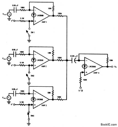
This circuit uses the four Norton amplifiers of an LM3900 to form an audio-mixing or selection circuit (Norton amplifier circuits are also shown in chapter 11). With this circuit,particular amplifiers can be gated off with dc-control signals applied to the (+) inputs. Amplifier 3 is active, with SW3 closed, while amplifiers 1 and 2 are driven into saturation by the +V input applied through the 5.1 -M resistors. (View)
View full Circuit Diagram | Comments | Reading(2474)
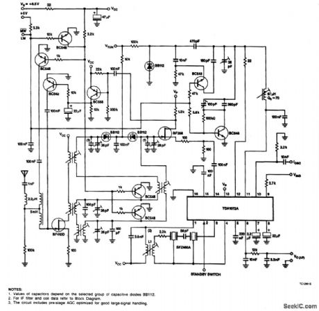
CAR_RADIO_WITH_CAPACITIVE_DIODE_TUNING_AND_ELECTRONIC_MW_LW_SWITCHING
Published:2009/7/6 2:09:00 Author:May
View full Circuit Diagram | Comments | Reading(1611)
20_dB_AUDIO_ROOSTER
Published:2009/7/5 23:32:00 Author:May
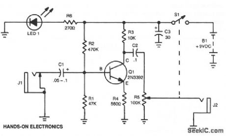
The amphrer's gain is nominally 20 dB.It frequency response is determined primarily by the value of just a few components-primarily C1 and R1.The values in the schematic diagram provide a response of ±3.0 dB from about 120 to over 20,000 Hz. Actually, the frequency response is flat from about 170 to well over 20,000 Hz;it's the low end that deviates from a flat frequency response. The low end's rotloff is primarily a function of capacitor C1, since R1's resistive value is fixed.If C1's value is changed to 0.1μF,the low end's corner frequency-the frequency at which the low end rolloff starts-is reduced to about 70 Hz. If you need an even deeper low end rolloff, change C1 to a 1.0-μF capacitor. If it's an electrolytic type, make certain that it's installed into the circuit with the correct polarity-with the positive terminal con-nected to Q1's base terminal. (View)
View full Circuit Diagram | Comments | Reading(868)
| Pages:25/54 At 202122232425262728293031323334353637383940Under 20 |
Circuit Categories
power supply circuit
Amplifier Circuit
Basic Circuit
LED and Light Circuit
Sensor Circuit
Signal Processing
Electrical Equipment Circuit
Control Circuit
Remote Control Circuit
A/D-D/A Converter Circuit
Audio Circuit
Measuring and Test Circuit
Communication Circuit
Computer-Related Circuit
555 Circuit
Automotive Circuit
Repairing Circuit