
Audio Circuit
Index 26
AUDIO_CIRCUIT_BRIDGE_LOAD_DRIVE
Published:2009/7/5 23:29:00 Author:May

This circuit shows a method which increases the power capability of a drive system for audio speakers. Two HA-2542s are used to operate on half cycles only, which greatly increases their power handling capability. Bridging the speaker, as shown, makes 200 mA of output current available to drive the load. The HA-5102 is used as an ac-coupled, low noise preamplifier, which drives the bridge circuit. (View)
View full Circuit Diagram | Comments | Reading(879)
TUNABLE_AUDIO_FILTER
Published:2009/7/5 22:13:00 Author:May
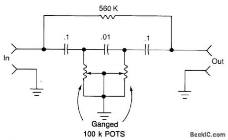
This filter covers the upper part of the audio passband and can be used to eliminate unwanted high frequencies from audio signals. (View)
View full Circuit Diagram | Comments | Reading(2074)
AUDIO_POWERED_NOISE_CUPPER
Published:2009/7/5 22:04:00 Author:May
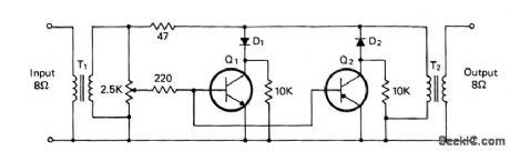
T1 and T2 are 600 to 8 ohm transformers (any transistor radio output transformers with 500 to 4 ohm impedance may be used). Q1 is a 2N2222 npn transistor, and Q2 is a 2N2907 pnp transistor. D1 and D2 1N270 signal diodes (HEP 134 or 135). Two transistors, powered by the audio power contained within the signal, will clip signal peaks which exceed the threshold established by the 2.5 K potentiometer. The diodes isolate the positive and negative clipping circuits represented by the npn and pnp transistors, respectively. A desired audio operating level can be established and the potentiometer needs little or no further adjustment. (View)
View full Circuit Diagram | Comments | Reading(1350)
PRECISE_AUDIO_CLIPPER
Published:2009/7/5 22:00:00 Author:May
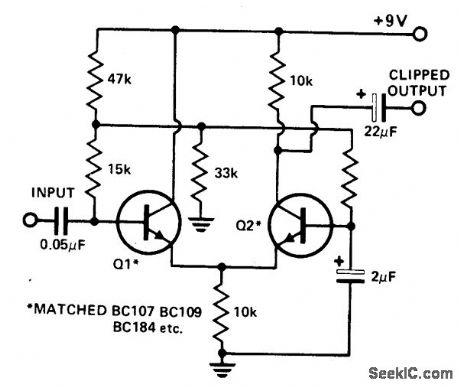
A differential amplifter makes an excellent audio clipper and can provide precise, symmetrical clipping. The circuit shown commences clipping at an input of 100 mV. The output commences clipping at ±3V. Matching Q7 and Q2 is necessary for good symmetrical clipping. (If some asymmetry can be tolerated, this need not be done.) (View)
View full Circuit Diagram | Comments | Reading(2500)
AUDIO_SQUELCH_CIRCUIT
Published:2009/7/5 22:00:00 Author:May
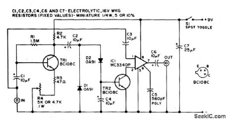
This simple audio squelch unit suppresses all input signals below a preset threshold. (View)
View full Circuit Diagram | Comments | Reading(3568)
SONAR_AUDIO_SELECTION_GATE
Published:2009/7/23 22:08:00 Author:Jessie
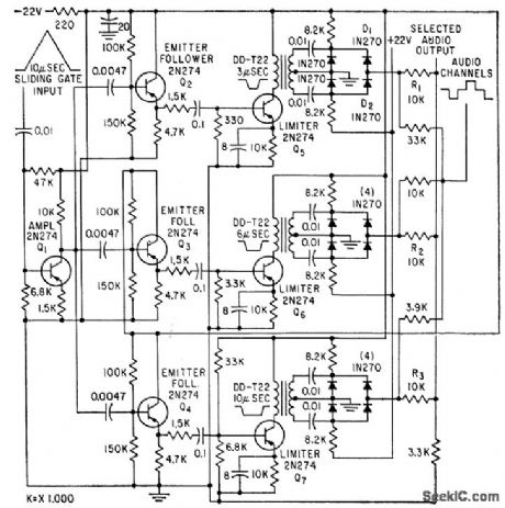
Triangular sliding gate of sonar target classifier selects from channel positions the sample chosen for monitoring by sonar operator-trainee, with smooth transition from one channel to another.-M. H. Damon, Jr., Tape Target Classifier Trains Sonar Operators, Electronics, 33:13, p 65-69. (View)
View full Circuit Diagram | Comments | Reading(1128)
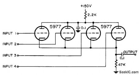
FIVE_INPUT_VIDEO_MIXER
Published:2009/7/23 23:28:00 Author:Jessie

Combines five radar marker inputs.-NBS, Handbook Preferred Circuits Navy Aeronautical Electronic Equipment, Vol. 1, Electron Tube Circuits, 1963, p N4-2. (View)
View full Circuit Diagram | Comments | Reading(945)
FOUR_TRIGGER_VIDEO_MIXER
Published:2009/7/23 23:27:00 Author:Jessie
Common-cathode arrangement with 47K cathode resistor allows nonadditive mixing of four positive trigger pulses having amplitudes in vicinity of 50 v.-NBS, Handbook Preferred Circuits Navy Aeronautical Electronic Equipment, Vol. 1, Electron lube Circuits, 1963, p N4-1. (View)
View full Circuit Diagram | Comments | Reading(987)
PREFERRED_PULSE_EMITTER_FOLLOWER
Published:2009/7/23 23:33:00 Author:Jessie
Two-stage cascaded emitter-follower is intended primarily as video line driver for positive pulses. Will drive load impedances as low as 50 ohms. Input impedance is about 80000 ohms in parallel with 25 pf. May be modified for negative inputs by replacing Q1 and Q2 with complementary pnp types and reversing polarity of collector supply. Voltage amplification is 0.975 and power gain is 30 db.-NBS, Handbook Preferred Circuits Navy Aeronautical Electronic Equipment, Vol. II, Semiconductor Device Circuits, 1962, PSC 21 (originally PC 221) p 21-2. (View)
View full Circuit Diagram | Comments | Reading(1500)
VOLTAGE_CONTROLLED_GAIN
Published:2009/7/23 23:38:00 Author:Jessie
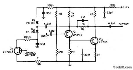
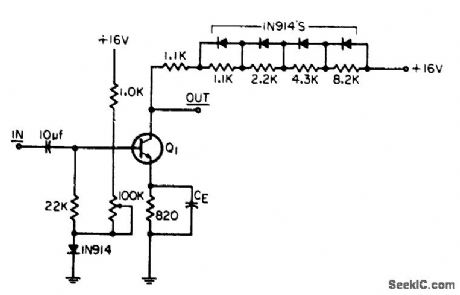
Silicon diodes serve to vary gin of wideband video amplifier over range from 2 to 32 db, with bandwidth remaining almost constant at 12 Mc and input impedance constant at 10K.-R. S. Hughes, A Wideband Video Amplifier with Variable Gain, EEE, 12:8, p 54-55. (View)
View full Circuit Diagram | Comments | Reading(0)
THREE_INPUT_IFF_MIXER
Published:2009/7/23 23:37:00 Author:Jessie
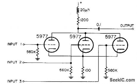
Common-plate connection serves for combining three iff signals. Common cathode resistor provides some degeneration.-NBS, Handbook Preferred Circuits Navy Aeronautical Electronic Equipment, Vol. 1, Electron Tube Circuits, 1963, p N4-3. (View)
View full Circuit Diagram | Comments | Reading(737)
TWO_INPUT_THREE_OUTPUT_MIXER
Published:2009/7/23 23:36:00 Author:Jessie
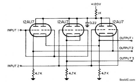
Combines two inputs and distributes them to each of three independent outputs, which are con netted to separate indicators.-NBS, Handbook Preferred Circuits Navy Aeronautical Electronic Equipment, Vol. 1, Electron Tube Circuits, 1963, p N4-3. (View)
View full Circuit Diagram | Comments | Reading(1075)
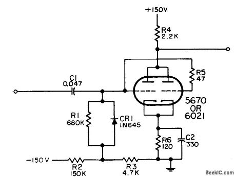
PREFERRED_LOW_LEVEL_PULSE_CATHODE_FOLLOWER
Published:2009/7/23 23:35:00 Author:Jessie
Used to couple output of low-level video stage to resistive load in applications where high-duty-factor signal makes direct coupling desirable.-NBS, Handbook Preferred Circuits Navy Aeronautical Electronic Equipment, Vol. I, Electron Tube Circuits, 1963, PC 22, p 22-2. (View)
View full Circuit Diagram | Comments | Reading(789)
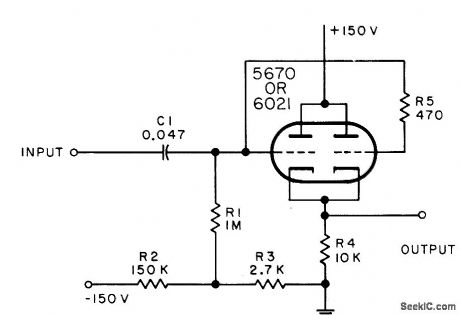
PREFERRED_TRIODE_DRIVER
Published:2009/7/23 23:35:00 Author:Jessie
Used to amplify video signals for intensity modulation of cathode-ray tube. Accepts positive inputs and gives negative output. Amplification is 5.-NBS, Handbook Preferred Circuits Navy Aeronautical Electronic Equipment, Val. I, Electron Tube Circuits, 1963, PC 27, p 27-2. (View)
View full Circuit Diagram | Comments | Reading(1879)
TWO_INPUT_MIXER
Published:2009/7/23 23:41:00 Author:Jessie

Used to combine range and heading markers in radar system.-NBS, Handbook Preferred Circuits Navy Aeronautical Electronic Equipment, Vol. 1, Electron Tube Circuits, 1963, p N4-1. (View)
View full Circuit Diagram | Comments | Reading(1072)
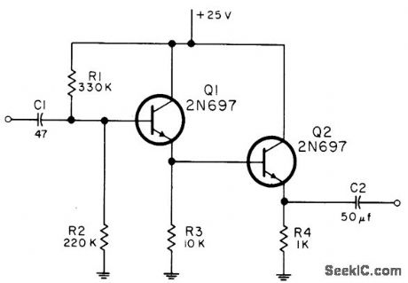
COMPRESSION_AMPLIFIER
Published:2009/7/23 23:39:00 Author:Jessie
Single transistor serves as compression amplifier having 50 db dynamic range, for nonsaturating amplification of widely ranging video signals. Provides minimum output of 1 v for 20 my input, but does not saturate with 6 v input. Circuit gain is minimum of 1 and maximum of 15. Two circuits are cascaded in actual application.-R. W. Cotterman, One Transistor, 50 Db Dynamic Range Compression Amplifier, EEE, 13:5, p 46. (View)
View full Circuit Diagram | Comments | Reading(1)
DUAL_GRID_PENTODE_MIXER
Published:2009/7/23 23:42:00 Author:Jessie
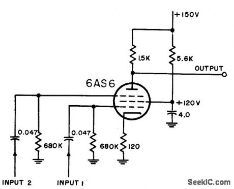
Uses 6AS6, in which suppressor grid has cutoff characteristic similar to control grid. Pulses of higher amplitude, such as markers, should be impressed on suppressor grid, since its transconductance is about one-fourth that of control grid. Chief drawback is need for large screen bypass capacitor.-NBS, Handbook Preferred Circuits Navy Aeronautical Electronic Equipment, Vol. 1, Electron Tube Circuits, 1963, p N4-9. (View)
View full Circuit Diagram | Comments | Reading(2596)
MIXER_LIMITER
Published:2009/7/23 23:42:00 Author:Jessie

Common-plate mixer uses diode-limiting coupling circuit to nullify adding feature. Bias voltage on diode sets limiting level-NBS, Handbook Preferred Circuits Navy Aeronautical Electronic Equipment, Vol. 1, Electron Tube Circuits, 1963, p N4-8. (View)
View full Circuit Diagram | Comments | Reading(974)
THREE_INPUT_TWO_PENTODE_MIXER
Published:2009/7/23 23:44:00 Author:Jessie
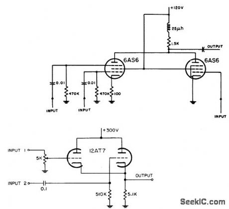
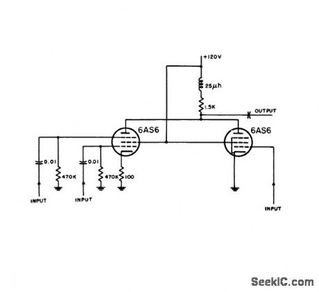
Distance markers and iff signals are inserted at separate grids on one tube, while radar video from input 3 is impressed on control grid of other pentode.-NBS, Handbook Preferred Circuits Navy Aeronautical Electronic Equipment, Vol. l, Electron Tube Circuits, 1963, p N4-4. (View)
View full Circuit Diagram | Comments | Reading(1166)
PREFERRED_COMMON_CATHODE_MIXER
Published:2009/7/23 23:43:00 Author:Jessie
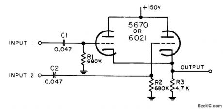
Combines video signals and pulses from two inputs, as for radar video, beacon signals, range markers, range strobes, and azimuth markers. Mixer is nonadditive and noninverting, can handle fast rise times, but amplification is less then unity and it cannot handle negative inputs.-NBS, Handbook Preferred Circuits Navy Aeronautical Electronic Equipment, Vol. I, Electron Tube Circuits, 1963, PC 23, p 23-2. (View)
View full Circuit Diagram | Comments | Reading(832)
| Pages:26/54 At 202122232425262728293031323334353637383940Under 20 |
Circuit Categories
power supply circuit
Amplifier Circuit
Basic Circuit
LED and Light Circuit
Sensor Circuit
Signal Processing
Electrical Equipment Circuit
Control Circuit
Remote Control Circuit
A/D-D/A Converter Circuit
Audio Circuit
Measuring and Test Circuit
Communication Circuit
Computer-Related Circuit
555 Circuit
Automotive Circuit
Repairing Circuit