
Audio Circuit
Index 29
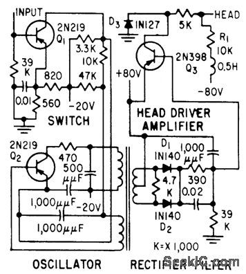
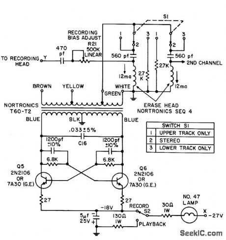
MAGNETIC_RECORDER_FOR_8_MM_MOVIE_CAMERA
Published:2009/7/24 4:46:00 Author:Jessie
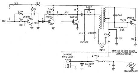
Silicon transistors serve as amplifiers and oscillator for recording on magnetic stripe. Frequency response is 100 to 1,0000 cps.-S. B. Gray, appliances and Housewares, Electronics, 36:20, p 46-49. (View)
View full Circuit Diagram | Comments | Reading(1287)
INSTRUMENTATION_RECORDER
Published:2009/7/24 4:46:00 Author:Jessie
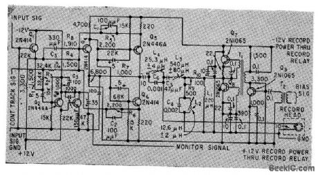
Bandpass is 250 cps to 250 kc. Uses input emitter-follower, head driver, bias amplifier, and monitor amplifier. Square-wave bias signal is supplied to each channel from master oscillator.-D. R. Steele, More Bandwidth for Magnetic Recorders, Electronics, 33:2, p 44-47. (View)
View full Circuit Diagram | Comments | Reading(833)
ZERO_SPEED_TAPE_PLAYBACK_OSCILLAIOR
Published:2009/7/24 4:45:00 Author:Jessie
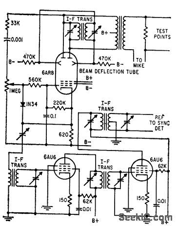
Permits playback of recorded high-frequency signals at exntremely slow speeds so highest frequency component is within limited band. width of pen recorder. 100,kc excitation oscillator and reference amplifier use beam defection tube.-M. E. Anderson, Magnetic Head Reads Tape at Zero Speed, Electronics, 32:10, p 58-60. (View)
View full Circuit Diagram | Comments | Reading(802)
INDEPENDENT_CONTROL_MVBR_TESTS_TRANSPORT
Published:2009/7/24 4:44:00 Author:Jessie
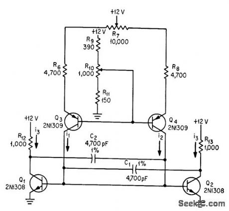
Timing resistors of conventional astable are replaced by adjustable constant-current sources using transistors Q3 and Q4. R7 controls mark/space ratio and R10 con trols frequency.-C. J. Dakin, Novel Multivibrators Test Tape Transports, Electronics, 37:7, p 40-43. (View)
View full Circuit Diagram | Comments | Reading(859)
MEASURING_TAPE_WOW_AND_FLUTTER
Published:2009/7/24 4:44:00 Author:Jessie
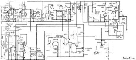
Circuit uses 40-kc carrier,calibrated cro,and various spectrum cutout filters to show all drift, wow, and flutter components from d-c to 4,000 cps for magnetic tape recorder.-J. T. Mullin, Precise Measurement of Wow and Flutter, Electronics, 32:26, p 100-102. (View)
View full Circuit Diagram | Comments | Reading(1004)
CRYSTAL_CONTROLLED_BLOCKING_OSCILLATOR
Published:2009/7/24 4:56:00 Author:Jessie
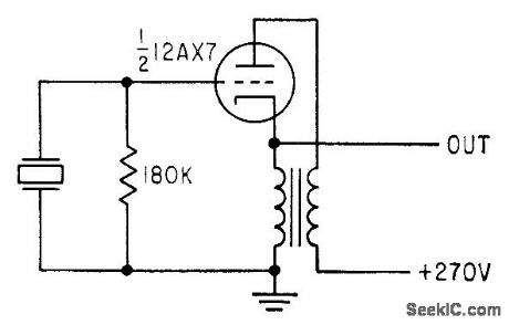
Used for recording 50-kc reference base on magnetic tape in 10-channel instrumentation system. Circuit is ordinary plate-to-cathode coupled blocking oscillator with crystal substituted for capacitor. If free-running frequency (without crystal) is lower than crystal frequency by no more than 40%, oscillator locks to crystal frequency.-P. S. Gengston, Blocking Oscillator is Crystal Controlled, Electronics, 31:25, p 88-90. (View)
View full Circuit Diagram | Comments | Reading(1012)
DIGITAL_DATA_WRITE_AMPLIFIER
Published:2009/7/24 4:55:00 Author:Jessie
Delivers 8-ma swing to record head. Rise time is 15 millisec, sufficient for nonreturn-to-zero re cording at 20 kc, using head with 50-mh inductance. Carrier-type amplifier overcomes usual stability and level problems associated with d-c amplifiers.-R. F. Shaw, Universal Tape Amplifiers for Digital Data Systems, Electronics, 31:41, p 91-93. (View)
View full Circuit Diagram | Comments | Reading(829)
SHOCKLEY_DIODE_MVBR_TESTS_TRANSPORTS
Published:2009/7/24 4:54:00 Author:Jessie
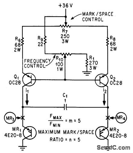
For testing tape transports, frequency can be varied over 15:1 range and mark/space ratio from 1:15to 15:1. Shockley diodes MR1 and MR2 serve as changeover switch. Two additional diodes, at MR3 and MR4, are needed if reverse voltage rating of diodes is less than their striking voltage.-C. J. Dakin, Novel Multivibrators Test Tape Transports, Electronics, 37:7, p 40-43. (View)
View full Circuit Diagram | Comments | Reading(1017)
ERASE_AND_BIAS_OSCILLATOR
Published:2009/7/24 4:53:00 Author:Jessie
Provides ample power for 60 db erasure of saturated tape, using 10 ma of 80-kc erase signal. Total power output is 1.5 W at efficiency of 60%. Bias current is same frequency.- Transistor Manual, Seventh Edition, General Electric Co., 1964, p 278. (View)
View full Circuit Diagram | Comments | Reading(1802)
COMPRESSOR
Published:2009/7/24 4:52:00 Author:Jessie
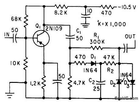
Has unity gain, expansion of 3 db, and compression of 12 db. Gain adjustments are automatic, Used to maintain even recording level during tape-recorded interviews.-E. C, miller, Audio Volume Compressor, Electronics, 33:2, p 62. (View)
View full Circuit Diagram | Comments | Reading(0)
Combined_contrast_and_backlight_supply_for_LCD_displays
Published:2009/7/24 5:23:00 Author:Jessie
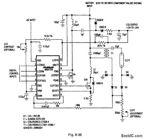
Figure 8-36 shows a MAX753 connected to provide both the contrast and backlight for LCD displays. The dc contrast voltage (-12 V to -24 V) is generated with a hybrid of boost regulator, plus Charge pump, under supervision of an on-board five-bit D/A converter, thus permitting microprocessor control of brightness. The circuit operates over a 6-V to 20-V range, draws 3-mA quiescent current, and is capable of 3-W output. MAXIM ENGINEERING JOURNAL, VOL. 3, 1994, P. 53.
(View)
View full Circuit Diagram | Comments | Reading(845)
WIRELESS_AM_MICROPHONE
Published:2009/6/30 2:59:00 Author:May
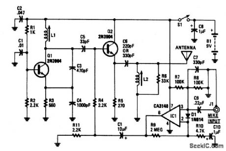
Transistor Q1 and its associated components comprise a tuneable rf oscillator. The rf signal is fed to transistor Q2, the modulator. Operational amplifier IC1 increases the audio signal and applids it through resistor R4 to the base of Q2. Tune an AM radio to an unused frequency between 800 to 1600 kHz. Tune L1 for a change in the audio level coming from the radio. Peak the output by adjusting L2. If L1 is disturbed, it may be necessary to readjust L2 for peak performance. Depending on the impedance of the microphone audio sensitivity can be increased by decreasing the value of R10 and vice versa. (View)
View full Circuit Diagram | Comments | Reading(1303)
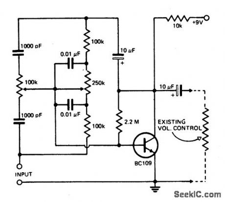
TONE_CONTROL_CIRCUIT
Published:2009/6/30 2:55:00 Author:May
A simple single-transistor circuit will give approximately 15 dB boost or cut at 100 Hz and 15 kHz respectively. A low noise audio type transistor is used, and the output can be fed directly into any existing amplifier volume con-trol to which the tone control is to be fitted. The gain of the circuit is near unity when con-trols are set in the flat position. (View)
View full Circuit Diagram | Comments | Reading(227)
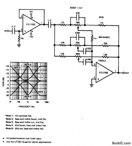
THREE_BAND_ACTIVE_TONE_CONTROL
Published:2009/6/30 2:49:00 Author:May
View full Circuit Diagram | Comments | Reading(0)
MICROPHONE_PREAMPLIFIER_WITH_TONE_CONTROL
Published:2009/6/30 2:47:00 Author:May
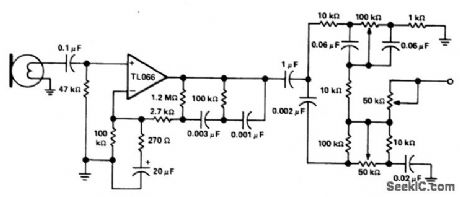
View full Circuit Diagram | Comments | Reading(1264)
NOISELESS_AUDIO_SWITCH
Published:2009/6/30 2:17:00 Author:May
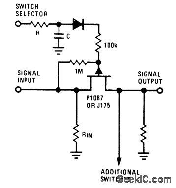
Deglitched current-mode switch using JFET can be placed directly on printefficircuit board instead of front panel, to minimize hum pickup and crosstalk.JFET allows transition time of drive to be adjusted with series resistor R and shunt capacitor C to provide noiseless switching of AF signals.Diode type is not critical. Any number of switches can be ganged.- Audio Handbook, National Semiconductor, Santa Clara, CA, 1977, p2-62. (View)
View full Circuit Diagram | Comments | Reading(3175)
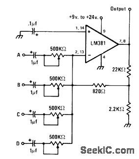
FOUR_CHANNEL_MIXER_1
Published:2009/6/30 2:16:00 Author:May
Combines AF signals from one to four sources into single audio signal for input of LM381 opamp that serves also as preamp. Shield mixer circuit and use shielded cable for all input leads to avoid pickup of 60-Hz field by high-gain opamp. Increasing supply voltagefrom minimum of 9V boosts outputsig-nal voltage.-J. A Sandier, 9 Easyto Build Projects under $9, Modern Electronics, July 1978, p 53-56. (View)
View full Circuit Diagram | Comments | Reading(1989)
60_dB_RANGE_FOR_AUDIO
Published:2009/6/30 2:03:00 Author:May
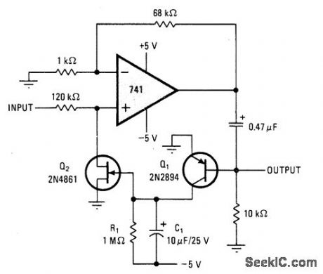
JFET acts as voltage-controlled resistor in peak-detecting control loop of 741 opamp. Input range is 20 mV to 20V, with response time of 1.2 ms and delay of 0.4.s.Outputisabout 1.4V P-P over entire 60-dB range,-N,Heckt、Automatic Gain Control Has 60~Decibel Range、Electronics,March 31,1977、p 107 (View)
View full Circuit Diagram | Comments | Reading(1249)
FOUR_CHANNEL_MIXER
Published:2009/6/30 1:53:00 Author:May
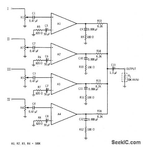
All four sections of RCA CA3048 quad differential amplifier are utilized in linear mixer providing gain of 20 dB for each channel. Designed for use with load of 10K or larger. All inputs are high impedance.-E. M Noll, Linear IC Principles, Experiments, and Projects, Howard VV. Sams, Indianapolis, IN, 1974, p 173 and 179. (View)
View full Circuit Diagram | Comments | Reading(0)
THREE_INPUT_MIXER
Published:2009/6/29 23:46:00 Author:May
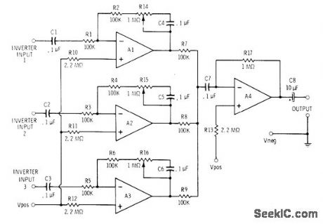
Motorola MC3401P or National LM3900 quad opamp serves for three input amplifiers each having adjustable gain range of 1 to about 11 and input impedance above about 100,000 ohms. Common outputs feed fourth opamp section connected as high-impedance amplifier. Maximum overall gain for mixeramplifier is about 300. Use well-filtered 9-15 V supply or battery capable of supplying 25 mA.-C. D. Rakes, Integrated Circuit Projects, Howard W. Sams, Indianapolis, IN, 1975, p 21-22. (View)
View full Circuit Diagram | Comments | Reading(2692)
| Pages:29/54 At 202122232425262728293031323334353637383940Under 20 |
Circuit Categories
power supply circuit
Amplifier Circuit
Basic Circuit
LED and Light Circuit
Sensor Circuit
Signal Processing
Electrical Equipment Circuit
Control Circuit
Remote Control Circuit
A/D-D/A Converter Circuit
Audio Circuit
Measuring and Test Circuit
Communication Circuit
Computer-Related Circuit
555 Circuit
Automotive Circuit
Repairing Circuit