
Audio Circuit
Index 28
STEREO_MULTIPLEX_PHASE_MODULATOR
Published:2009/7/24 3:19:00 Author:Jessie
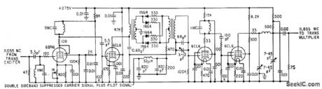
Circuit serves for frequency-modulating main terrier signal by stereophonic subcarrier in four-diode ring modulator to which 19-kc pilot subcarrier is also applied. Resultant signal is phase-modulated at same 11.055-Mc carrier frequency as input signal.-Modifying and F-M Transmitter for Compatible Stereo Multiplex, Electronics, 34:28, p 60-62. (View)
View full Circuit Diagram | Comments | Reading(1453)
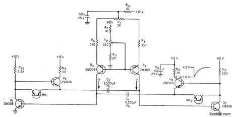
DRIVER
Published:2009/7/24 3:18:00 Author:Jessie
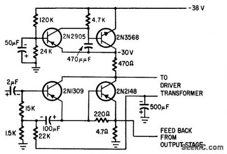
Upper pair of transistors provides voltage regulation, filtering, turn-on time delay, and decoupling for audio driver transistors below.-S. Messin and T. E. Nawalinski, A Solid Stale Stereo Set Built in Modules, Electronics, 38:16, p 88-92. (View)
View full Circuit Diagram | Comments | Reading(1171)
COMPACTRON_FOR_STEREO
Published:2009/7/24 3:17:00 Author:Jessie
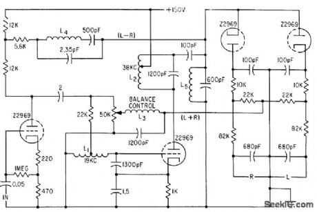
Z2969 compactron performs functions of two triodes and two diodes in circuit for adapting f-m receivers to stereo.-L. Dillon, Single Compactron Adapts Receiver for Stereo, Electronics, 34:43, p 62-64. (View)
View full Circuit Diagram | Comments | Reading(754)
PIN_DIODE_PROVIDES_120_DB_ACC_RANGE
Published:2009/7/24 3:26:00 Author:Jessie
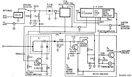
Dynamic signal range exceeds 120 db in fully transistorized Fisher TFM-1000 stereo set. Will receive signals as low as 1.5 microvolts without distortion, yet 0.5-V signals can be handled without overload or spurious response. Solid-state pin diode servos as gain-controlled attenuator. Separate 10.7-Mc tuned amplifier delivers agc voltage that, along with d-c amplifier, controls pin diode. Action of tuned amplifier is delayed until antenna signal is 1 mV.-F. L. Mergner, P-i-n Diode und FET's Improve F-M Reception, Electronics, 39:17, p 114-118. (View)
View full Circuit Diagram | Comments | Reading(887)
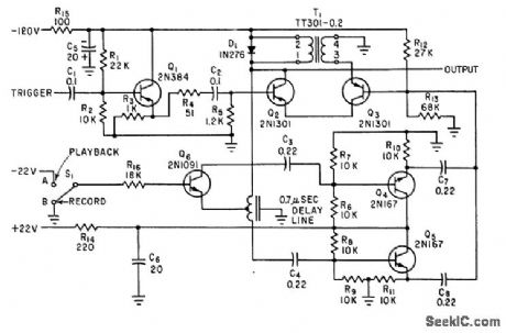
EIGHI_TRANSISTOR_MVBR
Published:2009/7/24 4:51:00 Author:Jessie
Emitter-followers Q5 and Q6 increase gain by providing low. impedance path for recharging timing capacitors. R7 controls mark/space ratio and R10 controls frequency.-C. J. Dakin, Novel Multivibrators Test Tape Transports, Electronics, 37:7, p 40-43. (View)
View full Circuit Diagram | Comments | Reading(859)
25_75_KC_FREQUENCY_MODULATOR
Published:2009/7/24 4:50:00 Author:Jessie
Frequency changes are linear within 1% with changes in input voltage. Circuit can easily be modified for other frequency ranges. Designed for use with magnetic tape recorders. Cf is primary frequency-determining element.-P. S. Bengston, Frequency Modulator Covers 25.75 Kc, Electronics, 31:31, p 100-106. (View)
View full Circuit Diagram | Comments | Reading(855)
MAG_TAPE_PRINT_THROUGH_SUPPRESSOR
Published:2009/7/24 4:50:00 Author:Jessie
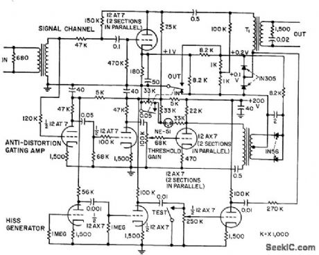
Echoes occurring before and after true signal in recorded magnetic tape stored for some lime, called print-through, and noticeable chiefly during soft musical passages and during recorded speech or singing, are sup pressed by biased. diode type of quieting are that silences audio channel whenever signal drops to 40 db below peak. Each diode is back-biased 0.1 V. If program peaks are 10 V, diodes become nonconducting for all signals more than 40 db below this peak. To prevent loss of desired signal near the zero axis, signals above the threshold are amplified, recti0ed, filtered, and used in time-constant circuit to keep diodes conducting throughout each spoken word.-D. Cronin, Squelch Circuit Mutes Magnetic Tape Echoes, Electronics, 31:19, p 66-67. (View)
View full Circuit Diagram | Comments | Reading(886)
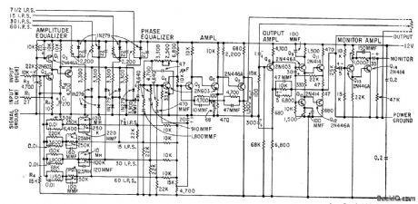
RECORDING_AMPIJFIER
Published:2009/7/24 4:49:00 Author:Jessie
Has sufficient input impedance for medium-high-impedance magnetic microphone. Includes equalization to produce flat response with Nortronics low-impedance recording head when playback preamp is adjusted for NAB equalization at tape speed of 7.5 inches per second.- Transistor Manual, Seventh Edition, General Electric Co., 1964, p 272. (View)
View full Circuit Diagram | Comments | Reading(1943)
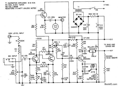
BATTERY_OPERATED_DICTATING_MACHINE
Published:2009/7/24 4:47:00 Author:Jessie
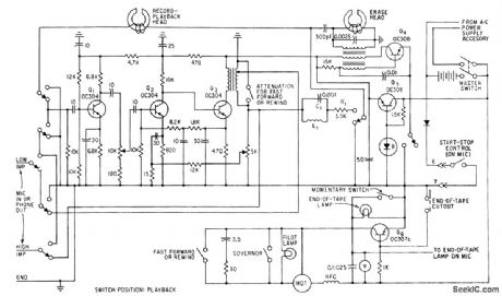
Amplifier voltage is regulated by Q5 and zener diode. Q6 functions as on-off switch controlled either by microphone switch or by metallic coating at both ends of two-track tape.-L. Hannemann, Pocket-size Dictating Machine, Electronics, 33:44, p 73. (View)
View full Circuit Diagram | Comments | Reading(814)
FET_REDUCES_PREAMP_NOISE
Published:2009/7/24 4:33:00 Author:Jessie
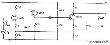
When impedance of source Vg is high, field-effect transistors reduce overall signal-to-noise folio in preamp for reproduce head of tope re corder.-J. J. Rado, Designing Input Circuits with Lowest Possible Noise, Electronics, 36:31, p 46-49. (View)
View full Circuit Diagram | Comments | Reading(892)
MAGNETIC_TRANSDUCER_PREAMP
Published:2009/7/24 4:31:00 Author:Jessie
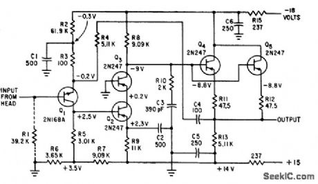
Gain is constant at 49 within 2% for ac source impedances ranging front 0 to 5,000 ohms, such as magnetic read heads. Gain remains con stunt within 3 db from 10 cps to 1 Mc.-S. R. Parris, Wideband Transistor Preamplifier Handles Low-Resistance Transducers, Electronics, 34:11, p 57-59. (View)
View full Circuit Diagram | Comments | Reading(1057)
SYNCHRONOUS_DETECTOR_FOR_ZERO_SPEED_TAPE_PLAYBACK
Published:2009/7/24 4:30:00 Author:Jessie
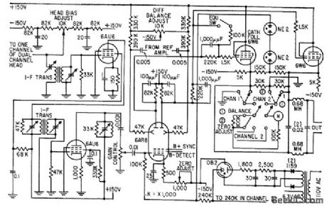
Tuned amplifiers with 200-kc center frequency and 20.kc bandwidth separate second harmonic signal containing intelligence from composite head output signal. Output of 6AR8 coupled to push-pull stage gives balanced output.-M. E. Anderson, Magnetic Head Reads Tape at Zero Speed, Electronics, 32:10, p 58-60. (View)
View full Circuit Diagram | Comments | Reading(1029)
VIDEO_TAPE_PREAMP
Published:2009/7/24 4:33:00 Author:Jessie
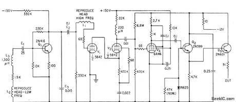
Two windings on reproduce head extend frequency response to 1 Mc. Winding L2 is connected conventionally to input of Q1; when transistor gain drops off at higher frequencies, L1 at input of first tube takes over. Preamp output to 91-ohm line is 1.5 V peak to peak.-G. N. Johnson, W. R. Johnson, and J. T. Mullin, Magnetic Recorder Response, Electronics, 34:10, p 186-188. (View)
View full Circuit Diagram | Comments | Reading(1020)
DELAY_LINE_PULSES_FOR_VIDEO_RECORDER
Published:2009/7/24 4:32:00 Author:Jessie
Blocking oscillator arrangement gives 0.3 microsec pulse length for recording by time-division multiplexing of S2 channels on two-track video recorder, and 0.8 microsec pulses when S1 is set for playback.-M. H. Damon and F. J. Messina, High-Density Storage of Wideband Analog Data, Electronics, 35:13, p 45-49. (View)
View full Circuit Diagram | Comments | Reading(1189)
DIRECT_REPRODUCE_CIRCUIT
Published:2009/7/24 4:31:00 Author:Jessie
Switching and equalization networks extend upper frequency limit to 250 kc for instrumentation tape. Amplifier section provides voltage gain of 14 db and output impedance below 50 ohms, for driving long, low-impedance lines.-D. R, Steele, More Bandwidth for Magnetic Recorders, Electronics, 33:2, p 44-47. (View)
View full Circuit Diagram | Comments | Reading(777)
FM_remote_speaker_system
Published:2009/7/24 4:41:00 Author:Jessie

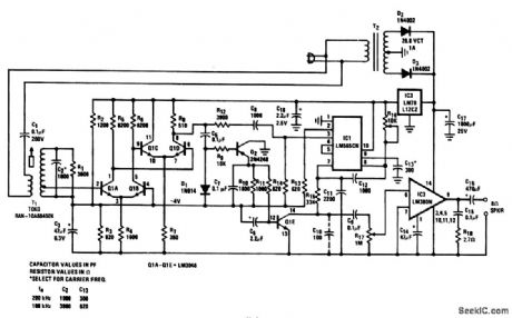
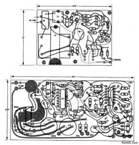
This complete carrier system is suitable for(high-qualit transmission of speech or music, and will operate from any ac outlet anywhere on a one-acre homesite. The frequency response is 20 to 20,000 Hz and THD_is under 0.5% for speech and music program material. The transmitter (Fig. 2-62A and 2-62C) is plugged into the ac line at a radio or stereo-system source The signal for the transmitter is ideally taken from the Monitor or Tape out connectors provided on component-system hi-fi receivers. The receiver (Fig 2-62B and 2:62B) amplifier ,limits, and demodulates the received FM signal in the presence of line-transient interference (sometimes as high as several hundred volts peak). The receiver also provides audio-mute in the absence of a carrier and 2.5-W audio output to a speaker. Transmitter carrier frequency fc is fixed near 100 or 200 kHz by C4/C7.The exact frequency is not important because T1 for both transmitter and receiver are tuned for maximum coupling to and from the ac line. Of course, both receiver and transmitter must be at the same frequency. With both transmitter and receiver operating (modulation is not necessary), tune the transmitter T1 for maximum, as measured with an ac VTVM at the receiver T1 secondary. Then tune the receiver T1 for maximum. Repeat as necessary. Set the receiver PLL free-running frequency with R16 near the center of its range. Rotate slowly in either direction until the PLL loses lock (as shown by a sharp increase in noise and a distorted output). Note the position of R16, and then repeat, rotating in the other direction. Note the new position, then center R16 between the two noted positions (a fine adjustment can be made for minimum noise if there is an SCR dimmer used in the house). Connect an audio signal to the transmitter input, and adjust RI for a maximum signal of about 0.1 V rms at pin 5 of IC1. This completes the adjustment. However, it might be necessary to readjust the receiver T1 slightly to minimize noise from SCR dimmers. (View)
View full Circuit Diagram | Comments | Reading(1291)
F_M_DEMODULATOR_FOR_TAPE_RECORDER
Published:2009/7/24 4:36:00 Author:Jessie
Removes low-frequency frequency-modulated nerve-potential signal from 7.5-kc carrier recorded on magnetic tope. Amplifier V3a feeds squarer V4 that is connected as Schmitt trigger to give square-wave output for differentiation by C8-R25. Negative going edge , of resulting square wave triggers monostable mvbr V5 which serves as demodulator.-K. D. Broadfoot, F-M Magnetic Tape System Records Low-Frequency Nerve-Fiber Potentials, Electronics, 34;28, p 66-67. (View)
View full Circuit Diagram | Comments | Reading(793)
HIGH_FREQUENCY_COMPENSATION
Published:2009/7/24 4:36:00 Author:Jessie
Compensates for 23 db/decade loss above 500 cps, in high-frequency response caused by spacing pickup head 1 mil from magnetic tape of vlf induction radio link.-E. A. Hanysz, J. E. Stevens, and A. Meduvsky, Communication System for Highway Traffic Control, Electronics, 33:42, p 81-83. (View)
View full Circuit Diagram | Comments | Reading(869)
SIRIPF_ON_FILM_RECORD_PLAYBACK
Published:2009/7/24 4:35:00 Author:Jessie
Transistor preamplifier is used only on playback. Two-stage recording amplifier has 10 db of negative feedback from secondary of output transformer to linearize frequency response and reduce distortion. Oscillator V3 supplies bias and erase current al 40 kc.-J. M. Moriarty, It. B. Johnson, and R. J. Roman, Magnetic Sound Track of 8-MM Home Movies, Electronics, 33:35, p 61-63. (View)
View full Circuit Diagram | Comments | Reading(751)
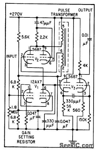
TIMING_SIGNAL_RECORDER
Published:2009/7/24 4:34:00 Author:Jessie
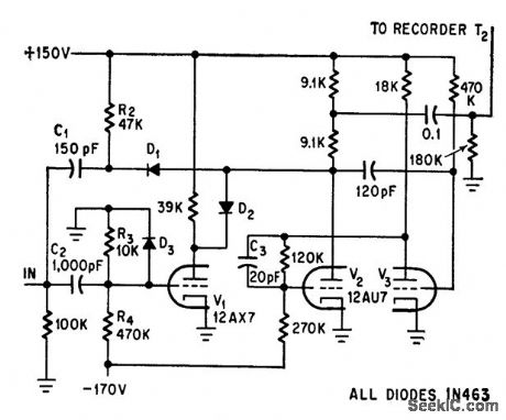
Low-cost analog magnetic rape recorder is modified to store rectangular event-timing signals for biomedical experiments. Input gate signal is differentiated in pulse shaper C1-R2. C2 with R3, R4, and D3 produce alternately positive and negative pulses corresponding to leading and trailing edges of gate. V1, biased off, blocks negative pulses. Output at T2 after inversion by V2 consists of 30-mkrosec negative pulses with peak of 50 V, which can be fed to tape recorder-G. Silverman, Modified Tape Recorder Stores Timing Signals, Electronics, 39:13, p 75-76. (View)
View full Circuit Diagram | Comments | Reading(1080)
| Pages:28/54 At 202122232425262728293031323334353637383940Under 20 |
Circuit Categories
power supply circuit
Amplifier Circuit
Basic Circuit
LED and Light Circuit
Sensor Circuit
Signal Processing
Electrical Equipment Circuit
Control Circuit
Remote Control Circuit
A/D-D/A Converter Circuit
Audio Circuit
Measuring and Test Circuit
Communication Circuit
Computer-Related Circuit
555 Circuit
Automotive Circuit
Repairing Circuit