
Audio Circuit
Index 21
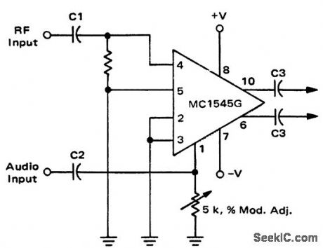
Balanced_modulator_using_an_MC1545G_wide_band_amplifier
Published:2009/7/20 6:51:00 Author:Jessie
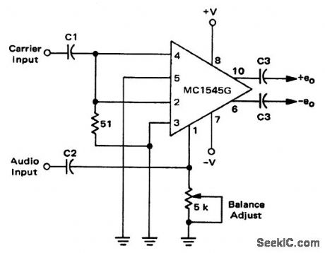
Balanced modulator using an MC1545G wide-band amplifier (courtesy Motorola Semiconductor Products Inc.). (View)
View full Circuit Diagram | Comments | Reading(1099)
250_MHz_BF_to_50_MHz_IF_mixer_using_a_2N3308_transistor
Published:2009/7/20 6:50:00 Author:Jessie
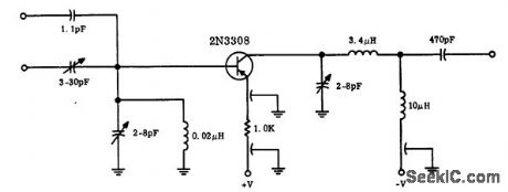
250 MHz BF to 50 MHz IF mixer using a 2N3308 transistor. The external local oscillator injection frequency is 300 MHz,The outputof the 2N3308 is tuned to the difference between the two signals (courtesy Motorola semiconductor Products Inc.). (View)
View full Circuit Diagram | Comments | Reading(958)
BF_amplifier_for_45_MHz_or_58_MHz_See_table_for_component_selection
Published:2009/7/20 6:49:00 Author:Jessie
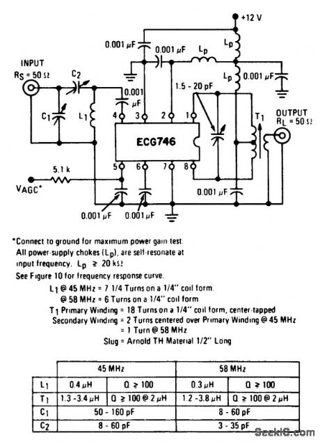
BF amplifier for 45 MHz or 58 MHz. See table for component selection (courtesy GTE Sylvania Incorporated). (View)
View full Circuit Diagram | Comments | Reading(1025)
30_MHz_IF_strip_for_microwave_or_radar_receivers_using_three_ECG703A_ICs_
Published:2009/7/20 6:45:00 Author:Jessie
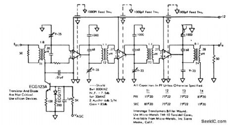
30 MHz IF strip for microwave or radar receivers using three ECG703A ICs (courtesy GTE Sylvania Incorporated). (View)
View full Circuit Diagram | Comments | Reading(1107)
Wide_band_differential_amplifier_with_AGO_using_an_MC1545G_
Published:2009/7/20 6:45:00 Author:Jessie
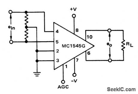
Wide-band differential amplifier with AGO using an MC1545G (courtesyMotorola Semiconductor Products Inc.). (View)
View full Circuit Diagram | Comments | Reading(948)
BF_IF_amplifier_for_30_MHz_60_MHz_100_MHz
Published:2009/7/20 6:44:00 Author:Jessie
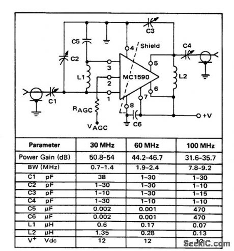
BF-IF amplifier for 30 MHz/60 MHz/100 MHz (courtesy Motorola Semiconductor Products Inc.). (View)
View full Circuit Diagram | Comments | Reading(1225)
10_MHz_RF_amplifier_using_an_ECG703A_IC
Published:2009/7/20 6:29:00 Author:Jessie
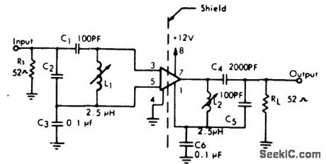
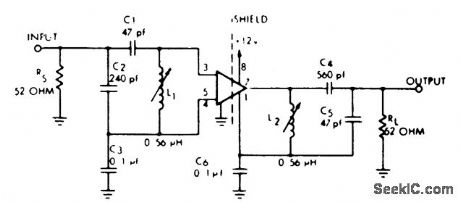
10 MHz RF amplifier using an ECG703A IC. The input signal is coupled to the amplifier through tank L1-C1-C2, tuned to 10 MHz. The capacitive divided C1-C2 provides impedance matching. Network L2-C4-C5 connects the amplifier to the load. A shield should be used between the input and output to prevent oscillations (courtesy GTE Sylvania Incorporated). (View)
View full Circuit Diagram | Comments | Reading(1048)
250_MHz_PF_to_50_MHz_IF_mixer_using_an_MM1941_transistor
Published:2009/7/20 6:28:00 Author:Jessie
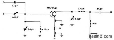
250 MHz PF to 50 MHz IF mixer using an MM1941 transistor. The external local oscillator injection frequency is 300 MHz. The output of the mixer is tuned to the difference between the two inputs (courtesy Motorola Semiconductor Products Inc.). (View)
View full Circuit Diagram | Comments | Reading(901)
30_MHz_PF_amplifier_using_an_ECG703A_IC
Published:2009/7/20 6:27:00 Author:Jessie
30 MHz PF amplifier using an ECG703A IC. The input signal is coupled through tank L1-C1-C2 to the ECG703A. Capacitors C1 and C2 form an impedance matching network. Network L2- C4- C5 coupled the output signal to the load. Use a shield between the input and output to prevent spurious oscillations (courtesy GTE Sylvania Incorporated). (View)
View full Circuit Diagram | Comments | Reading(967)
36_MHz_RFamplifier_using_a_3N211_dual_gate_MOSFET
Published:2009/7/20 23:45:00 Author:Jessie
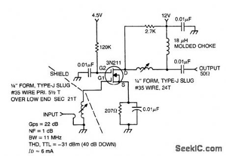
36 MHz RFamplifier using a 3N211 dual-gate MOSFET(courtesy Texas Instruments Incorporated). (View)
View full Circuit Diagram | Comments | Reading(1430)
45_MHz_RF_post_amplifier_using_two_3N204_dual_gate_MOSFETs
Published:2009/7/20 7:34:00 Author:Jessie
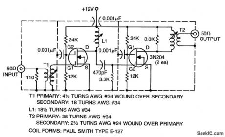
45 MHz RF post amplifier using two 3N204 dual-gate MOSFETs (courtesy Texas Instruments Incorporated). (View)
View full Circuit Diagram | Comments | Reading(1080)
25_watt_UHF_microstrip_amplifier_for_450_to_470_MHz
Published:2009/7/20 7:32:00 Author:Jessie
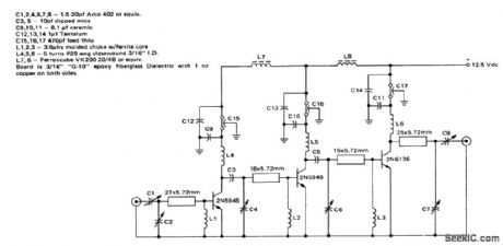
25-watt UHF microstrip amplifier for 450 to 470 MHz (courtesy Motorola Semiconductor Products Inc.). (View)
View full Circuit Diagram | Comments | Reading(1505)
Amplitude_modulator_using_an_AM1545G_wide_band_amplifier_
Published:2009/7/20 7:31:00 Author:Jessie
Amplitude modulator using an AM1545G wide-band amplifier (courtesy Motorola Semiconductor Products Inc.). (View)
View full Circuit Diagram | Comments | Reading(971)
_4_CHANNEL_MIXERV
Published:2009/7/9 3:07:00 Author:May

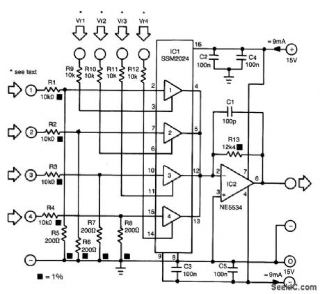


The proposed mixer is designed around four current-driven transconductance amplifiers contained in an SSM2024 from Precision Monolithics. To obtain a low offset and high control rejection, the four inputs should have an impedance to earth of about 200 Ω . These impedances are obtained from resistors R5 through R8, which also form part of a potential divider at each input.With the values in the diagram, the nominal input signal is 1 V (0 dBV). Distortion at that level is about 1%; at lower levels, it is not more than 0.3%.
The amplification of the current-driven amplifiers (CDAs) is determined by the current fed into the control inputs. These inputs form a virtual earth so that calculating the values of the bias resistors (to transform the inputs into voltage-driven inputs) is fairly simple.The output currents of the amplifier are summed by simply linking the output pins. The current-to-voltage convener, IC2, translates the combined output currents into an output voltage. The value of R13 ensures that the amplification of IC2 is unity. (View)
View full Circuit Diagram | Comments | Reading(1945)
RECEIVER_AUDIO_CIRCUIT
Published:2009/7/9 2:37:00 Author:May
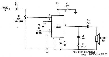
This simple receiver AF amplifier can supply several hundred milliwatts to an 8-Ω speaker. The gain is about 200X. If high gain is not needed, C2 can be deleted and a gain of 20 will be obtained. R1 and C6 are musts, otherwise ultrasonic (30 to 60 kHz) oscillations might occur. C6 can be 0.1 μF on all LM386N versions for protection against these oscillations. The supply voltage is typically 6 to 12 V. No heatsink is necessanr, but good grounding is a must. (View)
View full Circuit Diagram | Comments | Reading(1164)
107_MHz_IF_amplifier_using_a_3N204_dual_gate_MOSFET
Published:2009/7/20 20:25:00 Author:Jessie
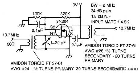
10.7 MHz IF amplifier using a 3N204 dual-gate MOSFET (courtesy Texas tnstruments tncorporated). (View)
View full Circuit Diagram | Comments | Reading(0)
Frequency_synthesizer_mixer_for_BC_operation_using_a_dual_gate_3N204_dual_gate_MOSFET
Published:2009/7/20 20:24:00 Author:Jessie
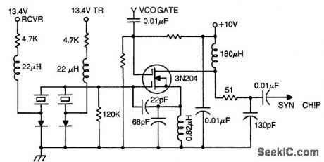
Frequency synthesizer mixer for BC operation using a dual-gate 3N204 dual-gate MOSFET (courtesy Texas Instruments Incorporated.). (View)
View full Circuit Diagram | Comments | Reading(1231)
105_MHz_low_noise_BF_amplifier_using_a_3N204_dual_gate_MOSFET
Published:2009/7/20 20:22:00 Author:Jessie
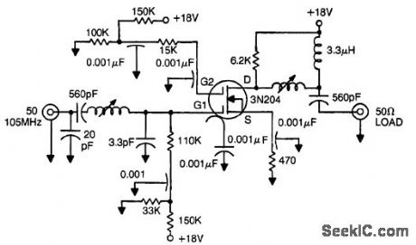
105 MHz low-noise BF amplifier using a 3N204 dual-gate MOSFET (courtesy Texas tnstruments tncorporated). (View)
View full Circuit Diagram | Comments | Reading(1058)
900_MHz_to_45_MHz_converter_using_dual_gate_3N204_MOSFETs_and_a_2N5245
Published:2009/7/20 20:21:00 Author:Jessie
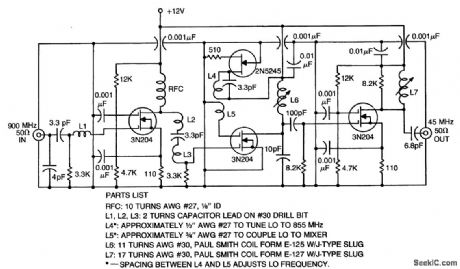
900 MHz to 45 MHz converter using dual-gate 3N204 MOSFETs and a 2N5245 (courtesy Texas Instruments mcorporated). (View)
View full Circuit Diagram | Comments | Reading(1138)
27_MHz_to_45_MHz_converter_using_two_3N204_MOSFETs_
Published:2009/7/20 20:20:00 Author:Jessie
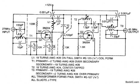
27 MHz to 45 MHz converter using two 3N204 MOSFETs (courtesy Texas Instruments Incorporated). (View)
View full Circuit Diagram | Comments | Reading(1666)
| Pages:21/54 At 202122232425262728293031323334353637383940Under 20 |
Circuit Categories
power supply circuit
Amplifier Circuit
Basic Circuit
LED and Light Circuit
Sensor Circuit
Signal Processing
Electrical Equipment Circuit
Control Circuit
Remote Control Circuit
A/D-D/A Converter Circuit
Audio Circuit
Measuring and Test Circuit
Communication Circuit
Computer-Related Circuit
555 Circuit
Automotive Circuit
Repairing Circuit